Table of Contents
Advertisement
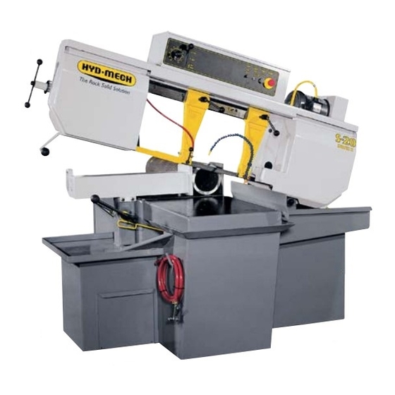
S-20/23
395426
January 2006 Revision A
THANK YOU,
On behalf of everyone at HYD . MECH, I would like to thank and congratulate you on your decision to purchase a
HYD . MECH band saw.
-
ting costs while boosting quality and productivity.
To ensure you are maximizing the power and versatility of your new HYD . MECH band saw, please take the time to famil-
iarize yourself and your employees with the correct operation and maintenance procedures as outlined in this manual.
Thank-you.
HYD . MECH GROUP LIMITED
P.O. BOX 1030, 1079 Parkinson Road
Woodstock, Ontario Canada, N4S 8A4
Phone: (519) 539-6341
Service 1-877-237-0914
Sales 1-877-276-SAWS(7297)
Fax (519) 539-5126
e-mail: info@hydmech.com
1
Advertisement
Table of Contents
Troubleshooting

Related Manuals for Hyd-Mech S-20


Summary of Contents for Hyd-Mech S-20
- Page 1 S-20/23 395426 January 2006 Revision A THANK YOU, On behalf of everyone at HYD . MECH, I would like to thank and congratulate you on your decision to purchase a HYD . MECH band saw. ting costs while boosting quality and productivity.
-
Page 3: Table Of Contents
TABLE OF CONTENTS SECTION 0 - SAFETY INSTRUCTIONS SUMMARY ............................0.1 FOREWORD ............................0.2 BASIC RULES ..........................0.4 RESPONSIBILITIES OF THE OWNER ...................0.5 RESPONSIBILITIES OF THE OPERATOR AND MAINTENANCE PERSONNEL ......0.6 SECTION 1 - INSTALLATION SAFETY PRECAUTIONS ........................1.1 VISUAL INSPECTION ........................1.2 LIFTING THE S20/23 WITH A FORK LIFT..................1.3 WRAPPED FOR SHIPPING ......................1.3 LEVELLING THE SAW ........................1.3 HYDRAULIC OIL ..........................1.3... - Page 4 SECTION 3 - MAINTENANCE & TROUBLESHOOTING BLADE CHANGING PROCEDURE....................3.2 BLADE GUIDE ADJUSTMENT .......................3.3 BLADE BRUSH ADJUSTMENT......................3.4 ANGLE BRAKE ADJUSTMENT......................3.4 BELT TENSION ADJUSTMENT (NOT APPLICABLE TO S23)............3.4 HEAD DOWN LIMIT SWITCH ......................3.5 LUBRICATION ..........................3.5 GEARBOX LUBRICATION S23 ......................3.6 GEARBOX LUBRICATION S20 WITH VFD OPTION ..............3.6 TROUBLE SHOOTING ........................3.7 SECTION 4 - ELECTRICAL S20 / S23 COMPONENT LAYOUT: VFD OPTION ................4.1...
-
Page 5: Summary
SECTION 0 - SAFETY INSTRUCTIONS SUMMARY All persons operating this machine must have read and understood all of the following sections of this Manual: Section 0 SAFETY Section 2 OPERATING INSTRUCTIONS However, as a memory aid, the following is a summary of the Safety Section. Put Safety First Mandatory Information –... -
Page 6: Foreword
FOREWORD Put Safety First! This Safety Section contains important information to help you work safely with your machine and describes the dangers inherent in our machines. Some of these dangers are obvious, while others are less evident. It really is important to PUT SAFETY FIRST. Make it a habit to consider the hazards associated with any action BEFORE from your supervisor. - Page 7 Signatures I have read and understood all parts of Section 0 – Safety, and Section 2 – Operating Instructions. Name Date Signature I have read and understood all parts of this Operation and Maintenance Manual. Name Date Signature...
-
Page 8: Basic Rules
Manual. Hyd-Mech Group cannot accept any liability for personal injury or property damage due to operator errors or non-compliance with the Safety and Operating Instructions contained in this Manual. -
Page 9: Responsibilities Of The Owner
Responsibilities of the owner Organization of work This Operation and Maintenance Manual must always be kept near the machine so that it is accessible to all concerned. The general, statutory and other legal regulations on accident prevention and environmental protection must also be observed, in addition to the Manual material. -
Page 10: Responsibilities Of The Operator And Maintenance Personnel
Responsibilities of the operator and maintenance personnel Safety equipment All machines are delivered with safety equipment that must not be removed or bypassed during operation. The correct functioning of safety equipment on the machine must be checked: at the start of every shift. after maintenance and repair work Emergency Stop Button ( E-Stops) Always be aware of the location of the Emergency Stop Button(s). - Page 11 Gloves Experience has shown that careless use of gloves around machinery is a major factor in serious hand injuries. Gloves should not be worn when operating or adjusting the machine, except: Wear protective gloves when handling bandsaw blades at blade changes. Gloves may be worn when handling work pieces, only if the machine is in Manual Mode and the bandsaw blade is not running.
- Page 12 On Hyd-Mech machines the Master Disconnect Switch will be of one of three types: Rotary switch mounted in electrical control cabinet door and inter-locked with door...
-
Page 13: Section 1 - Installation
SAFETY PRECAUTIONS The S-20/23 has been designed to give years of reliable service. It is essential that operators be alerted to the safe opera- tion of this saw, and the practices to avoid that could lead to injury. The following safety rules are at the minimum neces- sary for the safe installation, operation, and maintenance of the saw. -
Page 14: Visual Inspection
VISUAL INSPECTION Head - keep away from moving blade Vise - never load stock with the blade moving Head - watch for head descending to the table Pivot - check for head movement blockage Drive - secure pulley cover when running... -
Page 15: Lifting The S20/23 With A Fork Lift
HYDRAULIC OIL The S-20/23 is supplied with ISO VG22 hydraulic oil. Substitutes must be of the same vis- cosity in order for the system to work properly. -
Page 16: Cutting Fluid
In order to provide a safe operation as well as to prevent potential damage to the As supplied your new S-20/23 is set to run on three phase voltage or single phase. The supply voltage of the machine displayed on the Serial # Plate and the voltage label. -
Page 17: Wiring Connections For Machines With Vfd Option
Wiring Connections for machines with VFD option L1, L2, L3, and ground terminals The power cable should be routed found inside of the box through the hole found at the bottom right of the box. A suitable strain relief should be used. -
Page 19: Section 2 - Operating Instructions
SECTION 2 – OPERATING INSTRUCTIONS The operator control panel provides the operator with all the controls necessary to operate the saw after the cutting angle has been set and the stock has been loaded and secured. All of the electrical functions and the Feed Rate setting are operated from the control panel. -
Page 20: Electrical Controls (S20 Vfd / S23 Vfd Option)
ELECTRICAL CONTROLS (S20 VFD / S23 VFD OPTION) Blade Speed (1BS) – m/min). Adjustment should be made only when the blade is running. Coolant Switch (1SS) – ON: OFF: AUTO: Blade running. Blade Start (5PB) – A green push button. The blade will not start with the head in the down position, if any safety switch- es are not closed, or if the emergency stop is depressed. -
Page 21: Electrical Controls (S20H Vfd / S23H Vfd Option)
ELECTRICAL CONTROLS (S20H VFD / S23H VFD OPTION) Coolant Switch (1SS) – ON: OFF: AUTO: Blade running. Blade Speed (1BS) – m/min). Adjustment should be made only when the blade is running. Blade Start (5PB) – A green push button. The blade will not start with the head in the down position, if any safety switch- es are not closed, or if the emergency stop is depressed. -
Page 22: Blade Basics
BLADE BASICS Technology is rapidly changing all aspects of production machining. Metal cutoff is no exception. The advances price of high-technology blades. Variable pitch, bi-metal blades (like the 4/6 or ¾ bi-metal blade supplied with the machine) last much longer, cut faster and more accurately than conventional carbon steel blades. In order extremely slow feed rate. -
Page 23: Optimum Blade Pitch
OPTIMUM BLADE PITCH Teeth per inch (T.P.I.) Selecting a blade with a proper tooth pitch is important in order to achieve optimal cutting rates and good blade life. many teeth per inch is recommended. For wide materials a blade with a coarse pitch should be used. -
Page 24: Head Swing And Brake
BLADE SPEED SELECTION (not applicable to S-23) The blade speed of the S-20 can be changed between four different speeds. The speed is determined by the ratio of the pulleys that drive the V belt. The four pulley sets give the optional speeds of 90, 140, 220 and 310 ft/min. -
Page 25: Changing Belt Position
CHANGING BELT POSITION To change the blade speed of the S-20 it is necessary to release the V belt tension and move the belt to another set of pulley grooves. The tension on the V belt is maintained by means of a toggle handle assembly that moves the motor. -
Page 27: Section 3 - Maintenance & Troubleshooting
SECTION 3 - MAINTENANCE & TROUBLESHOOTING Switch off before beginning work. The emergency switch, which is used to turn the hydraulics off, should not be the only means of shutting the power off before cleaning or performing maintenance to the machine. The main power disconnect should be switched off and locked. -
Page 28: Blade Changing Procedure
Repeat this process until both wheels IDLER WHEEL ADJUSTMENT S-20 Line On the blade tensioner slide assembly, there are three 9/16” hex head bolts. Loosen the two bolts at the left end by ¼... -
Page 29: Blade Guide Adjustment
S-23 BLADE TENSION ASSEMBLY S-20 BLADE TENSION ASSEMBLY BLADE GUIDE ADJUSTMENT At the bottom of the guide arms are the carbide blade guide assemblies, the photo shows the carbide- locking handle. These assemblies will need to be adjusted occasionally as the carbide pads become worn. -
Page 30: Blade Brush Adjustment
BLADE BRUSH ADJUSTMENT The machine leaves the factory with the blade brush adjusted for maximum life of the brush. This setting places the ends of the blade brush wires so as to contact the blade at the bottom of the blade gullets. The plastic drive wheel that is driven by the drive wheel face should be held against the blade face with the minimum force that is necessary. -
Page 31: Head Down Limit Switch
HEAD DOWN LIMIT SWITCH The head down limit switch operates to cut power to the blade motor and the coolant pump motor when the Head has descended to the bottom of its travel in the Manual mode. The Head is adjusted so that the blade will descend slightly past the level of the vise wear strips. -
Page 32: Gearbox Lubrication S23
GEARBOX LUBRICATION S23 synthetic oil. This oil has an ISO Viscosity Grade of 320 that is optimum for ambient temperatures from 20-70 used, this be equivelent viscosity wise and of the synthetic type. The lubricant must also have the necessary EP and anti-foaming additives. -
Page 33: Trouble Shooting
TROUBLE SHOOTING PROBLEM PROBLEM CAUSE Carbide guide adjustment incorrect (adjust). Feed rate excessive (reduce). 1 Cutting out of square vertically. Blade worn (replace). Guide arms too far apart. Blade pitch incorrect . Angle not set correctly (adjust). Stock not square in vise. (reset material) 2 Cutting out of square horizontally. -
Page 35: Section 4 - Electrical
SECTION 4 - ELECTRICAL S20 / S23 Component Layout: VFD OPTION The electrical schematics show some components labeled as TB1 to TB2 and these components are physically mounted on din rails. The illustration below shows the location of the Din rails with the installed components and the designated TB number. - Page 36 MS2M MS2M A close up view of TB1 is shown. It is located in the main panel (MP). For example, if the electrical schematic shows a terminal, described as This indicates that the terminal is located on din rail TB1 and is terminal #1. This would indicate that the terminal is mounted on TB1 and is terminal #5.
- Page 37 TB2 is located in the HMI panel (Human Machine Interface). This houses the selector switches and push buttons. As in the main panel the same concept applies, for example: This indicates that the terminal is located on din rail TB2 and is terminal #3.
-
Page 38: S22H / S23H Component Location: Vfd Option
S22H / S23H Component Location: VFD Option The electrical schematics show some components labeled as TB1 and TB2 and these components are physically mount- ed on din rails. The illustration below shows the location of the Din rails with the installed components and the designated TB number. - Page 39 A close up view of TB1 is shown. It is located in the main panel (MP). For example, if the electrical schematic shows a terminal, described as This indicates that the terminal is located on din rail TB1 and is terminal #1. This would indicate that the terminal is mounted on TB1 and is terminal #3.
- Page 40 TB2 is located in the HMI panel (Human Machine Interface). This houses the selector switches and push buttons. As in the main panel the same concept applies, for example: This indicates that the terminal is located on din rail TB2 and is terminal #4.
-
Page 41: For Electrical Schematics And Component Parts List See Pdf On Attached Cd
DT (Device Tag) The remainder of the components in the control panel are labeled and are referred to in the documentation under the DT heading. For example: DT, CR6 is the Coolant relay labeled CR6. DT, LS2 is the limit switch for Head Down function labeled LS2. DT, MS 2M is the contactor labeled MS 2M. -
Page 43: Section 5 - Hydraulic
SECTION 5 - HYDRAULIC FOR HYDRAULIC SCHEMATICS AND PLUMBING DIAGRAMS SEE PDF ON ATTACHED CD. -
Page 45: Section 6 - Mechanical Assemblies
SECTION 6 - MECHANICAL ASSEMBLIES For Mechanical Assembly Drawings see PDF on attached CD... -
Page 47: Section 7 - Options
SECTION 7 - OPTIONS BLADE BREAKAGE SWITCH (Standard on CE machines) Blade breakage switch shuts down blade drive and hydraulic pump motor (S22H, S23H option) in case blade band tension is lost or the blade snaps. It will disable machine operation until the new blade is installed and tensioned. -
Page 48: Hydraulic Power Pack (S20H / S23H)
HYDRAULIC POWER PACK (S20H / S23H): System operates head up and vise. Power pack is mounted on the door at the drive side of the infeed table. Parts consist of .25Hp (.19 kW) electric motor, relief valve assembly, gear pump and tank assembly This option requires special heads and vise cylinder. -
Page 49: Overhead Bundling (Hydraulic S20H / S23H)
OVERHEAD BUNDLING (HYDRAULIC S20H / S23H) 1. The relative speed of the bundling jaws and vise can be adjusted with the needle valves at each cylinder control valve control valve a) The material should be loaded into the machine vises and advanced to a position where a trim can be performed. -
Page 50: Work Lamp Assembly
WORK LAMP ASSEMBLY WORK LAMP 371790 MATERIAL STOP WORK STOP ASSEMBLY S22-G15-00A FOR OPTIONAL ASSEMBLY DRAWINGS SEE PDF ON ATTACHED CD. -
Page 51: Section 8 - Specifications
SECTION 8 - SPECIFICATIONS 90° Rectangle: 13” x 18” 90° Rectangle: 330 mm x 457 mm 90° Round: 13” diameter 90° Round: 330 mm 45° Rectangle: 13” x 10.75” 45° Rectangle: 305 mm x 273 mm CAPACITY: 45° Round: 12” diameter 45°... -
Page 52: S20 Cutting Capacity
S20 CUTTING CAPACITY... -
Page 53: S20 Machine Layout (Sheet 1)
S20 MACHINE LAYOUT (SHEET 1) -
Page 54: S20 Machine Layout (Sheet 2)
S20 MACHINE LAYOUT (SHEET 2) - Page 55 90º Rectangle: 16” x 18” 90º Rectangle: 406 mm x 457 mm 90º Round: 16” diameter 90º Round: 406 mm diameter 45º Rectangle: 16” x 10” 45º Rectangle: 406 mm x 254 mm CAPACITY: 45º Round: 12” diameter 45º Round: 305 mm diameter 60º...
-
Page 56: S23 Cutting Capacity
S23 CUTTING CAPACITY... -
Page 57: S23 Machine Layout (Sheet 1)
S23 MACHINE LAYOUT (SHEET 1) -
Page 58: S23 Machine Layout (Sheet 2)
S23 MACHINE LAYOUT (SHEET 2) -
Page 59: Section 9 - Warranty
SECTION 9 - WARRANTY Warranty Hyd-Mech Group Limited warrants parts/components on each new S20/23 bandsaw to be free from failure resulting from defective material and workmanship under proper use and service for a period of two years by the user.
Need help?
Do you have a question about the S-20 and is the answer not in the manual?
Questions and answers