Table of Contents
Advertisement
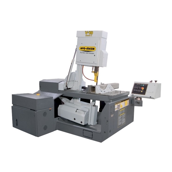
V18
393433
THANK YOU,
On behalf of everyone at HYD·MECH Group Limited, we would like to thank and congratulate you on your decision to
purchase a HYD·MECH bandsaw.
Your new machine is now ready to play a key role in increasing the efficiency of your operation, helping you to reduce cost
while boosting quality and productivity.
To ensure you are maximizing the power and versatility of your new HYD·MECH bandsaw, please take the time to
familiarize yourself and your employees with the correct operation and maintenance procedures as outlined in this
manual. Please keep this instruction manual for future reference in a known location and easily accessible to all users of
the device.
HYD·MECH offers a great variety of options, components, and features for its various models. Therefore, some of the
equipment described in this manual (various illustrations and drawings) may not be applicable to your particular machine.
The information and specifications provided in this manual were accurate at the time of printing. HYD·MECH reserves the
right to discontinue or change specifications or design at any time without notice and without incurring any obligation.
Thank you.
Hyd·Mech Group Limited
P.O. Box 1659, 1079 Parkinson Road
Woodstock, Ontario, N4S 0A9
Phone : (519) 539-6341
Service : 1-877-237-0914
Sales : 1-877-276-SAWS (7297)
Fax : (519) 539-5126
e-mail : info@hydmech.com
Printed JULY 2016
1
Advertisement
Table of Contents
Troubleshooting

Subscribe to Our Youtube Channel
Related Manuals for Hyd-Mech V18


Summary of Contents for Hyd-Mech V18
- Page 1 393433 THANK YOU, On behalf of everyone at HYD·MECH Group Limited, we would like to thank and congratulate you on your decision to purchase a HYD·MECH bandsaw. Your new machine is now ready to play a key role in increasing the efficiency of your operation, helping you to reduce cost while boosting quality and productivity.
-
Page 4: Table Of Contents
SECTION 1 - INSTALLATION SAFETY CONSIDERATIONS ......................1.1 LIFTING AND SHIPPING .........................1.2 REMOVING HEAD RESTRAINT ......................1.2 INSTALLATION OF THE CONTROL PANEL ...................1.3 LEVELLING THE V18 ........................1.4 HYDRAULIC OIL ..........................1.4 CUTTING FLUID ..........................1.4 WIRING CONNECTIONS .........................1.5 BLADE TENSION CHECK .......................1.5 EARTH GROUNDING PROCEDURE ....................1.5 SECTION 2 - OPERATING INSTRUCTIONS START-UP ............................2.1... - Page 5 BLADE TRACKING ..........................3.3 DRIVE WHEEL ADJUSTMENT ......................3.3 IDLER WHEEL ADJUSTMENT ......................3.4 BLADE BRUSH ADJUSTMENT .......................3.4 BLADE GUIDES ..........................3.4 GEARBOX LUBRICATION (V18 WITH A412 GEARBOX) ...............3.5 LUBRICATION ..........................3.5 HYDRAULIC MAINTENANCE ......................3.6 TROUBLE SHOOTING GUIDE ......................3.7 ELECTRICAL TROUBLESHOOTING ....................3.7 CUTTING AND BLADE TROUBLESHOOTING ................3.8 SERVICE RECORD &...
-
Page 6: Section 0 - Safety Instructions
SECTION 0 - SAFETY INSTRUCTIONS SUMMARY All persons operating this machine must have read and understood all of the following sections of this Manual: Section 0 SAFETY Section 2 OPERATING INSTRUCTIONS However, as a memory aid, the following is a summary of the Safety Section. Put Safety First Mandatory Information –... - Page 7 FOREWORD Put Safety First! This Safety Section contains important information to help you work safely with your machine and describes the dangers inherent to bandsaws. Some of these dangers are obvious, while others are less evident. It really is important to PUT SAFETY FIRST. Make it a habit to consider the hazards associated with any action BEFORE you do it.
-
Page 8: Basic Rules
Manual, and When all operations and procedures are in compliance with this Manual. Hyd-Mech Group cannot accept any liability for personal injury or property damage due to operator errors or non-compliance with the Safety and Operating Instructions contained in this Manual. -
Page 9: Responsibilities Of The Operator And Maintenance Personnel
Define responsibilities Clearly define exactly who is responsible for operating, setting-up, servicing and repairing the machine. Define the responsibilities of the machine operator and authorize him to refuse any instructions by third parties if they run contrary to the machine’s safety. Persons being trained on the machine may only work on or with the machine under the constant supervision of an experienced operator. - Page 10 Clothing, jewellery, protective equipment Personnel operating or working on the machine must not wear un-restrained long hair, loose-fitting clothes and dangling jewellery. When operating or working on the machine, always wear suitable, officially tested personal protective equipment such as safety glasses and safety boots and any other equipment required by workplace regulations.
-
Page 11: Safety Hazard Labels
On Hyd-Mech machines the Master Disconnect Switch will be of one of four types: • Rotary switch mounted in electrical control cabinet door and inter-locked with door. • Rotary switch mounted on the side of the operator interface console. Lever switch mounted in separate box on the machine. - Page 12 MOVING BANDSAW BLADE WILL CUT Do NOT operate with guard removed. Do NOT place hands or fingers near moving bandsaw blade. For blade changing, always follow the proper Blade Changing Procedure, as given in Section 3 of this manual. PINCH POINT Machine parts may move without warning, either because the machine is operating automatically, or because another person initiates the motion.
-
Page 13: Section 1 - Installation
If not performing properly, the machine should be stopped immediately and set-up, or repaired by a qualified person. Stock must not be loaded while the blade is running and the V18 should not be operated unless all guards, covers, and doors are in place and closed. -
Page 14: Lifting And Shipping
LIFTING AND SHIPPING To lift a V18 bandsaw with a forklift, it must have a minimum capacity of 7500 LB. at 48” from the mast as well as 6’ forks. Always lift the saw from the front as shown. The forks must not be under the electrical / hydraulic cabinet. The saw will have 4 x 4 steel tubes under each leveling foot, these must be removed (save the bolts for anchoring) before positioning the saw. -
Page 15: Installation Of The Control Panel
INSTALLATION OF THE CONTROL PANEL The V18 comes equipped with an articulating control panel. This panel is normally removed and placed on the saw table for shipping purposes. The control panel MUST BE REINSTALLED PRIOR TO MACHINE START UP. Take lifting precau- tions when installing the panel as it weights 150 LB. -
Page 16: Levelling The V18
HYDRAULIC OIL The V18 bandsaw is supplied with Texaco Rando HD46 oil. If it is necessary to change the oil to a different brand it is good practice to empty the hydraulic tank using a pump. Fill the hydraulic tank approximately 1/3 full with the new brand of oil and operate the saw through several cycles with maximum cylinder extension. -
Page 17: Wiring Connections
WIRING CONNECTIONS After the machine is levelled and anchored the necessary power hook-up needs to be performed. In order to provide safe operation as well as to prevent potential damage to the machine, only qualified personnel should make the connections. L1, L2, L3 BEFORE START-UP THE FOLLOWING TWO POINTS SHOULD BE CHECKED... -
Page 18: Section 2 - Operating Instructions
START-UP The V18 control console has been designed to simplify the operation of the saw so that the operator has the ability to stop any function at any time, and to be able to control all the functions of the saw remotely. -
Page 19: Saw Cutting Controls
MANUAL OPERATION CONTROLS The electrical switches and buttons on the control panel allow for full manual operation of the V18. The operation of each is detailed on the following pages. Manual operation controls. - Page 20 MANUAL OPERATION CONTROLS TOP ROW MIST: This OPTIONAL switch has three positions - AUTO, OFF and ON. OFF: No mist coolant. AUTO: The mist coolant sprays only when the Head is advancing into the cut. Mist coolant sprays any time the machine is under power. LEFT VISE: This switch operates the vise on the left side of the blade.
- Page 21 MANUAL OPERATION CONTROLS CENTER ROW COOLANT: This switch has three positions - AUTO, OFF and ON. OFF: No coolant flow. AUTO: The coolant flows only when the Head is advancing into the cut. Coolant flows any time the machine is under power, permitting wash down with the hose. RIGHT VISE: This switch operates the vise on the right side of blade.
-
Page 22: Additional Manual Controls
BOTTOM ROW HEAD SWING LEFT: Depressing this button fully will cause the head to swing quickly to the left until the button is re- leased or the head reaches the swing limit. Depressing this button partially will cause the head to swing slowly to the left allowing for fine adjustment. -
Page 23: Blade Basics
BLADE BASICS Technology is rapidly changing all aspects of production machining. Metal cutoff is no exception. The advances made in the bandsaw blade industry have definitely brought down the cost per cut, despite the three fold higher price of high tech- nology blades. - Page 24 CHART EXAMPLE #1 We will use the parameters chart to set up the saw for cutting 8” (200mm) Diameter #1045 Carbon Steel. STEP 1, DETERMINE EFFECTIVE MATERIAL WIDTH - W ( inches ) or (mm) Effective material width, W (in.) for most common shapes of materials, is the widest solid part of the material to be in contact with blade during cutting.
- Page 25 STEP 3, DETERMINE OPTIMUM BLADE PITCH - TEETH PER INCH (T.P.I.) Selecting a blade with proper tooth pitch is important in order to achieve optimal cutting rates and good blade life. For cutting narrow or thin wall structural materials a fine blade with many teeth per inch (T.P.I.) is recommended. For wide materials a blade with a coarse pitch should be used.
- Page 26 The following table gives examples of the optimum blade speeds for different materials. Optimum Optimum Blade Speed Blade Speed Materials ft/min m/min 5" (125mm) diameter solid medium carbon steel 10" (250mm) I-Beam 4" x 4" (100mm x 100mm) Rect tube 1/4" (6mm) wall 4"...
- Page 27 Feed Rate, continued If the saw is fitted with a blade coarser than optimum (e.g.. 1.4/2.5 TPI) we can still use the graph, but we go to the 1.4/2.5 curve. As a result we find that the FEED RATE is decreased to 1.3 in/min (133mm/min) for this blade. If however, the ma- chine is fitted with a finer than optimum blade (e.g.
-
Page 28: Mechanical Controls
HYDRAULIC CHIP CONVEYOR (optional) An option available with the V18 is the hydraulic chip conveyor drive which provides an easier means of clean- ing out the chips that accumulate while cutting. A Chip Conveyor control switch for the hydraulically driven chip conveyor is located on the operator control panel. -
Page 29: Head Swing Brake
Re-install the brake cover. BRAKE COVER 1- Brake plate (V18-272-01) 2- Lock Nut 3- Brake Nut 4- Front Brake Pad (V18-271-01B) 5- Rear Brake Pad (V18-271-01B) 6- Brake Pad Support (V18-271-02A) 7- Roll Pin Note: Canted head machine takes only 1 Front brake pad support item #6 CLEARANCE .010”... -
Page 30: Section 3 - Maintenance And Trouble Shooting
SECTION 3 - MAINTENANCE AND TROUBLE SHOOTING LOCK-OUT Purpose: To prevent injury to workers caused by unexpected start-up of machines being worked on, Where the starting of a machine or device may endanger the safety of a worker. a) Control switches or other control mechanisms shall be locked out, b) Other effective precautions necessary to prevent such starting shall be taken. -
Page 31: Blade Change Procedure
3. The V18 blade is only exposed to the operator at the cutting area. A hinged cover protects the operator from the blade between the Idler wheel assembly and the actual cutting area. A black knob on the cover allows it to be easily pulled open. -
Page 32: Blade Installation
“push/pull” arrangement. For the idler wheel there is single adjuster assembly in the centre of the idler shaft under the cover on the front of the head. Hyd-Mech Service should be contacted before making any adjustment to the wheel position. -
Page 33: Idler Wheel Adjustment
If the brush gets worn to approximately 70% of its original 3” diameter it should be re- placed. A brush may be purchased from your HYD-MECH dealer. Blade brush & adjusting screw (circled). -
Page 34: Gearbox Lubrication (V18 With A412 Gearbox)
GEARBOX LUBRICATION (V18 WITH A412 GEARBOX) The Bonfiglioli A412 gearbox used on the V18 is supplied with 5.0 litres (1.32 US gallon) of Mobil SHC 630 synthetic oil. This oil has an ISO Viscosity Grade of 220 that is optimum for ambient temperatures from 10 – 40 Deg C [70 – 104 Deg F]. -
Page 35: Hydraulic Maintenance
The hydraulic tank capacity is 8 US gallons. NOTE: The V18 is shipped from the factory with Texaco Rando HD 46 oil. Generally any brand of recognized mineral hy- draulic oil with the same properties should be compatible with Texaco Rando HD 46 oil, but to avoid any risk we suggest staying with Texaco Rando HD 46. -
Page 36: Trouble Shooting Guide
Most problems which may occur have one of the relatively simple solutions which appear in this section. If the solution is not found here, contact the Hyd-Mech Distributor from whom you purchased your bandsaw. They have trained field ser- vice personnel who will be able to rectify the problem. -
Page 37: Cutting And Blade Troubleshooting
CUTTING AND BLADE TROUBLESHOOTING SOLUTION PROBLEMS CAUSE 1a) Change the blade and check alignment 1) Saw is cutting out of square. 1a) Blade is worn. with new blade. 1b) Replace the worn guide or adjust the 1b) Blade guide is worn or not guide until the blade is cutting square. - Page 38 PROBLEMS CAUSE SOLUTION 8) Head will not advance. 8a) The feed rate valve is closed. 8a) Pointer is at “0”. Turn the Feed Rate Knob counter clockwise to open. 8b) The Feed Force limit is too 8b) Increase the Feed Force limit. low.
-
Page 39: Service Record & Notes
SERVICE RECORD & NOTES DATE SERVICED BY COMMENTS 3.10... -
Page 40: Section 4 - Electrical
SECTION 4 - ELECTRICAL V18 COMPONENT LOCATION The electrical schematics show some components labeled as TB1 to TB6 and these components are physically mounted on DIN rails. The illustration below shows the location of the DIN rails with the installed components and the designated TB number. - Page 41 TERMINAL BLOCK 1 Terminals 1 - 33 Page 4.1 shows the position of TB1 in the control panel. It can be seen that TB1 has only terminals mounted to it. For example, if the electrical schematic shows a terminal, described as This indicates that the terminal is located on din rail TB1 and is terminal #6.
- Page 42 TERMINAL BLOCK 2 A close up view of TB2 is shown. Page 4.1 shows the position of TB2 in the control panel. For example, if the electrical schematic shows a terminal, described as This indicates that the terminal is located on din rail TB2 and is terminal #3. would indicate that the terminal is mounted on TB2 and is terminal #6.
- Page 43 TERMINAL BLOCK 3 A close up view of TB3 is shown. Page 4.1 shows the position of TB3 in the control panel. For example, if the electrical schematic shows a terminal, described as This indicates that the terminal is located on din rail TB3 and is terminal #4. would indicate that the terminal is mounted on TB3 and is terminal #9.
- Page 44 TERMINAL BLOCK 3 . Close up view of Control Relays TERMINAL BLOCK 4 (TB4): See page 4.7 TERMINAL BLOCK 5 (TB5) : TB5 IS NOT USED on the V18 machine...
- Page 45 TERMINAL BLOCK 6 TB6 Contains ground terminals (partially visible) mounted either side of the contactors MS1M & MS2M and are indicated on the schematic as: & The mounting location in the control panel is shown on page 1.
- Page 46 TERMINAL BLOCK 4 TB4 is located in the HMI panel (Human Machine Interface). This houses the selector switches and push buttons. As in the main panel, the same concept applies. For example: This indicates that the terminal is located on din rail TB4 and is terminal #25.
-
Page 47: For Electrical Schematics And Parts List See Pdf On Attached Cd
DT (Device Tag) The remainder of the components in the control panel are labeled and are referred to in the documentation under the DT heading. For example: DT, CR20 is the Left Vise control relay labeled CR20. DT, LS2 is the limit switch for Head Advance function labeled LS2. DT, MS 2M is the contactor labeled MS 2M. -
Page 48: Section 5 - Hydraulics
SECTION 5 - HYDRAULICS The V18 hydraulic system does not require any special work on a new machine before its start-up. The hydraulic tank is filled with Texaco Rando HD 46 oil and all machine functions have been tested at the factory to ensure the proper opera- tion upon start-up. -
Page 49: Gland Assemblies
CYLINDER ASSEMBLIES GLAND ASSEMBLIES CYLINDER DIAMETER O RING BACKUP GLAND LOADED WIPER O RING U CAP 2.0” 362960 362785 CS20-GL-01A 362830 363330 2.5” 362970 362790 CS25-GL-01B 362815 363335 3.0” 362985 362795 CS30-GL-01A 362815 363335 3.5” 362995 362800 CS35-GL-01A 362835 363340 4.0”... -
Page 50: For Hydraulic Schematics And Plumbing Diagrams See Pdf On Attached Cd
FOR HYDRAULIC SCHEMATICS AND PLUMBING DIAGRAMS SEE PDF ON ATTACHED CD... -
Page 52: Section 6 - Mechanical Assemblies
SECTION 6 - MECHANICAL ASSEMBLIES MECHANICAL ASSEMBLY DRAWINGS & PARTS LIST: SEE PDF ON ATTACHED CD... -
Page 53: Section 7 - Options
SECTION 7 - OPTIONS OPTIONAL ASSEMBLY DRAWINGS: SEE PDF ON ATTACHED CD... -
Page 54: Section 8 - Specifications
SECTION 8 - SPECIFICATIONS V18 SPECIFICATIONS V-18 BANDSAW SPECIFICATIONS at 90º rectangular 18"x 31"(457mm x 787mm) at 90º rectangular 18"x 28"(457mm x 711mm) with 6º option at 90º rectangular 18"x18"(457mm x 457mm) with 6º cant option 17.5" (445mm) with tall vise insert option at 90º... -
Page 55: V18 Layout
V18 LAYOUT... -
Page 56: Section 9 - Warranty
ORAL, INCLUDING WITHOUT LIMITATION ANY IMPLIED WARRANTIES OF MERCHANTABILITY OR FITNESS FOR A PARTICULAR PURPOSE. This warranty may not be changed, altered, or modified in any way except in writing by Hyd-Mech Group Limited HYD·MECH GROUP LIMITED 1079 Parkinson Road P.O.
Need help?
Do you have a question about the V18 and is the answer not in the manual?
Questions and answers
What size blade for a V-18