
Subscribe to Our Youtube Channel
Related Manuals for Dante DNZ1880YM2


Summary of Contents for Dante DNZ1880YM2
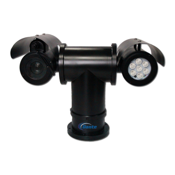
- Page 1 DNZ1880YM 2MP, 30x D/N Explosion Proof Integrated IP IR PTZ System User Operations Manual Model Number: DNZ1880YM2 Description: IP Explosion Proof, Integrated IR PTZ Positioning System 2MP with 30x Optical Zoom...
- Page 2 DNA1880YM2 EXPLOSION PROOF INFRARED PTZ CAMERA·MANUAL Quality Assurance: Quality Assurance: Quality Quality Assurance: Assurance: When DNA1880YM2 is in warranty period, we offer free maintenance. Other causes will be treated accordingly: If User does not follow manual instruction, may damage product; Open device without permission, may damage product;...
- Page 3 DNA1880YM2 EXPLOSION PROOF INFRARED PTZ CAMERA·MANUAL SAFETY SAFETY SAFETY SAFETY The safe application period can last for years, from the date of production. Each device has series number as production date, which can find on its nameplate. Please do operation after knowing well about device, safe cautions and instruction.
- Page 4 The manual is just for reference. It may have differences after the device upgrade. Please contact with Dante Security to get the latest version. We have checked the manual before releasing. We reserve rights to change its content without prior notice.
- Page 5 DNA1880YM2 EXPLOSION PROOF INFRARED PTZ CAMERA·MANUAL Explosion proof structure description Explosion proof structure description Explosion proof structure description Explosion proof structure description The device will not cause external blast even if explosive gas mixture enters in product inner chamber. Unit is assembled with thick cover, joint width, length, max and its surface temperature into consideration before design, so as to guarantee its explosion proof character.
- Page 6 DNA1880YM2 EXPLOSION PROOF INFRARED PTZ CAMERA·MANUAL T T T T ransporting Unit ransporting Unit ransporting Unit ransporting Unit Power off: use hands to transport it from bottom or both ends. Do not transport by camera and lights housing, or pull cable. When power is on: do not transport, open unit, or pull cables.
-
Page 7: Table Of Contents
DNA1880YM2 EXPLOSION PROOF INFRARED PTZ CAMERA·MANUAL Content Content Content Content 1. Preamble ........................7 1.1 Specification ..........Error! Bookmark not defined. 1.2 Features ............Error! Bookmark not defined. 1.3 Range of application ..................7 1.4 Mechanical ............. Error! Bookmark not defined. 1.5 Electrical ............ -
Page 8: Specification
DNA1880YM2 EXPLOSION PROOF INFRARED PTZ CAMERA·MANUAL 1. 1. 1. 1. I I I I ntroduction ntroduction ntroduction ntroduction Thanks for purchasing our products. DNA1880YM2 are explosion proof PTZ camera with IR lights, which can be installed in areas of volatile gas and flammable powder, such as hydrogen and hydrocarbon gas in the plants, chemical factory, and offshore platforms. -
Page 9: Mechanical
DNA1880YM2 EXPLOSION PROOF INFRARED PTZ CAMERA·MANUAL 1.4 Mechanical 1.4 Mechanical 1.4 Mechanical 1.4 Mechanical Material Stainless steel 316L sprayed with anti-corrosive paint Optional Auto heating when less than 15℃ it will operated on auto (±5℃), Horizontal rotation 0~360 °continuous, max 40°/s Vertical rotation 0~±90°, Max 30°/s Return trip... -
Page 10: Electrical
DNA1880YM2 EXPLOSION PROOF INFRARED PTZ CAMERA·MANUAL 1.5 Electrical 1.5 Electrical 1.5 Electrical 1.5 Electrical Voltage, current AC220V (AC85-265V) less than 1A or AC24V less than 3A Power ≤75W Cable connection Integrated cable Communication RS-485 Control communication Rate 2400~19200bps Protocol PELCO-D Preset 128, accuracy≤0.1°... -
Page 11: Installation And Debugging
DNA1880YM2 EXPLOSION PROOF INFRARED PTZ CAMERA·MANUAL 2. Installation 2. Installation and and D D D D ebugging ebugging 2. Installation 2. Installation ebugging ebugging 2.1 Precautions 2.1 Precautions 2.1 Precautions 2.1 Precautions before installation before installation before installation before installation The device has been tested and placed under burn-in controls for 48 hours before delivery. -
Page 12: Cable Connection
DNA1880YM2 EXPLOSION PROOF INFRARED PTZ CAMERA·MANUAL W W W W arnings arnings arnings arnings before installation before installation before installation before installation Do not disassemble device, and follow manual instruction. Please make cable connection as 1.5 items required. Please make sure the device working pressure, temperature, humidity follow 1.6 items requirement. - Page 13 DNA1880YM2 EXPLOSION PROOF INFRARED PTZ CAMERA·MANUAL Fig.2.2.1.2 Profile for connection 2. 2. 2. 2.2 2 2 2 .2 .2 .2 .2 Armored cable Armored cable Armored cable Armored cable Cut circled at 15mm distance from cable outer layer, and leave 15mm shielded layer.
-
Page 14: Fix Bracket
DNA1880YM2 EXPLOSION PROOF INFRARED PTZ CAMERA·MANUAL 2.3 Installation 2.3 Installation 2.3 Installation 2.3 Installation optional optional optional bracket optional bracket bracket bracket In order to avoid excessive shaking from panning and tilting, it is best to install at top of pole. - Page 15 DNA1880YM2 EXPLOSION PROOF INFRARED PTZ CAMERA·MANUAL Fig 2.3.1.4 wall bracket side view 2.4 Support 2.4 Support d d d d evice and connection evice and connection 2.4 Support 2.4 Support evice and connection evice and connection In consideration of explosion proof device will be installed at hazardous area, please make connections and tests in the laboratory before carrying out installation on site.
-
Page 16: Debugging
DNA1880YM2 EXPLOSION PROOF INFRARED PTZ CAMERA·MANUAL 2.5 Debugging 2.5 Debugging 2.5 Debugging 2.5 Debugging 2.5.1 System 2.5.1 System connection connections s s s 2.5.1 System 2.5.1 System connection connection Laptop Fig 2.5.1 system connection way Network camera can be connected with LAN or WAN, user can do surveillance or record by internet. - Page 17 DNA1880YM2 EXPLOSION PROOF INFRARED PTZ CAMERA·MANUAL blue white alarm input 1 blue alarm input 2 black white alarm input grounded orange Alarm output1 orange white Alarm output 1 MB network Unshielded twisted pair (UTP) thick brown (L) AC24V ±10% Power thick blue (N) thick yellow green (G) Grounded...
- Page 18 DNA1880YM2 EXPLOSION PROOF INFRARED PTZ CAMERA·MANUAL The 1-2 of switch code is for baud rate, Baud rate set as sheet 2.5.3.2. sheet 2.5.3.2: Switch code Baud rate(bps) 2400 4800 9600 19200 The 3-5of switch code is for protocol, as sheet 2.5.3.3. Sheet 2.5.3.3:...
- Page 19 DNA1880YM2 EXPLOSION PROOF INFRARED PTZ CAMERA·MANUAL SAMSUNG SCC-4223P SHILIN Support PELCO-D Camera SAMSUNG SANYO Remarks: customer can offer required camera type 2.5.4 2.5.4 check before power supply check before power supply 2.5.4 2.5.4 check before power supply check before power supply Check power cable, network cable connection is in right way, and code settings according to above.
-
Page 20: Trouble Removal
DNA1880YM2 EXPLOSION PROOF INFRARED PTZ CAMERA·MANUAL 2.5.7 Wiper and infrared lights 2.5.7 Wiper and infrared lights 2.5.7 Wiper and infrared lights 2.5.7 Wiper and infrared lights manual manual manual control manual control controls s s s control Assistant 1 is to control wiper, AUX On, wiper work; AUX off, Wiper stop. Assistant 2 is to control lights. -
Page 21: Transport, Storage, Maintenance
After five years, please change rubber sealing ring. 5. Statement 5. Statement 5. Statement 5. Statement This instruction cannot include all issue of installation or maintenance. If any support is needed, please contact Dante Security. - Page 22 DNA1880YM2 EXPLOSION PROOF INFRARED PTZ CAMERA·MANUAL Appendix: restricted substances, Appendix: restricted substances, Appendix: restricted substances, Appendix: restricted substances, or element list or element list or element list or element list Electronic Information product pollution control and manage regulations, restricted substances, or element list Electronic Information product pollution control and manage regulations, restricted substances, or element list Name...
- Page 23 Network Camera Web3.0 Operation Manual Version 1.0.1...
- Page 24 Table of Contents Network Config ..........................1 Network Connection ..................... 1 Log in ..........................1 Live ..............................6 Encode Setup ........................ 6 System Menu ......................... 7 Video Window Function Option .................. 7 Video Window Setup ....................8 2.4.1 Image Adjustment ..................... 8 2.4.2 Original Size ......................
- Page 25 5.1.1 Conditions ....................... 30 5.1.2 Video ........................42 5.1.3 Audio ........................53 Network ......................... 56 5.2.1 TCP/IP ........................56 5.2.2 Connection ......................58 5.2.3 PPPoE ........................60 5.2.4 DDNS ........................61 5.2.5 IP filter ........................62 5.2.6 SMTP (e-mail) ..................... 63 5.2.7 UPnP ........................
- Page 26 5.5.6 Remote control ......................131 5.5.6 Auto Maintenance ....................132 5.5.7 Upgrade ........................ 133 Information ......................... 133 5.6.1 Version ........................133 5.6.2 Log ........................134 5.6.3 Online User ......................134 Alarm ............................136 Log out ............................138...
- Page 27 Important The following functions are for reference only. Some series products may not support all the functions listed below.
-
Page 28: Network Config
1 Network Config 1.1 Network Connection Network camera and PC connection mainly has two ways, see Figure 1- 1 and Figure 1-2. Figure 1- 1 Figure 1-2 Before you access network camera via the Internet, you need to have its IP address. User may use Config Tool to search IP of the network camera. - Page 29 After successful connection, the login interface is shown as in Figure 1-3; input your user name and password. Default factory username is admin and password is admin. Figure 1-3 The system will display “Update Password” prompt box for your first login, users need to modify the password and save it properly.
- Page 30 Figure 1-5 Click on “Please click here to download and install the plug-in”. The system pops up warning information to ask you whether run or save this plug-in. See Figure 1-6. Figure 1-6...
- Page 31 You must either run or save the file to local and install it. Follow the following steps. Click on run, you will see Figure 1-7and Figure 1-8. Figure 1-7...
- Page 32 Figure 1-8 When plug-in installation completes, the installation page closes automatically. The web-end will refresh automatically, and then you can view video captured by the camera. Figure 1-9...
-
Page 33: Live
2 Live After you logged in, you can see the live monitor window. See Figure 2-1. Figure 2-1 There are four sections: Section 1: Encode setup bar Section 2: System menu Section 3: Window function option bar Section 4: Window adjust bar 2.1 Encode Setup Note: Some series don’t support sub stream 2. -
Page 34: System Menu
Parameter Function Click it to enable main stream video monitoring and click again Main stream to disable it. Generally for storage and monitor. Click it to enable Sub Stream 1 video monitoring and click again Sub Stream 1 to disable it. When network bandwidth is insufficient, it substitutes main stream for monitoring. -
Page 35: Video Window Setup
When the video is in the original status, click it you can Digital select any zone to zoom in. In the non-original status, Zoom you can drag the zoom-in zone in specified range. Right click mouse to restore previous status. Click it;... -
Page 36: Original Size
Figure 2-6 Click this button to display/hide image control interface. Click it to open picture setup interface. This interface is on the top right pane. Please refer to the following sheet for detailed information. Parameter Function Video It is to adjust monitor video Note: setup brightness. -
Page 37: Width And Height Ratio
2.4.4 Width and Height Ratio Click it to restore original ratio or suitable window. 2.4.5 Fluency Adjustment There are three levels of fluency for you to select (Realtime, Normal, and Fluency). The default is normal. 2.4.6 Rules Info Click the button, preview image will display intelligent rules after enabling; it is “enable” by default. 2.4.7 Zoom and Focus Click this button and the focus zooming interface appears on the right of preview interface, as shown in Figure 2-7, click left mouse button to adjust focus zooming configuration. - Page 38 Parameter Function Adjust the focal length of the lens by clicking or long pressing “+”“-”buttons. Zoom The speed is used to adjust the length of one step during single click. Adjust the sharpness of the lens by clicking or long pressing“+”,“-” buttons. Focus Step length is used to adjust the length of one step with one click.
- Page 39 Figure 2-8 parameter Note Installation Mode Three modes which are ceiling mount, wall mount and ground mount. It represents the display mode of the current image (default supports original image mode), the display modes may be different according to different installation modes.
- Page 40 parameter Note 360°expanded rectangular panorama +6 independent sub image, both the sub image and the subbox in the expanded rectangular panorama support zoom and 1P+6 movement, for the expanded rectangular panorama also supports left and right starting point movement. Original image + 8 independent sub images, both the sub image and the subbox in the original image support zoom and movement.
- Page 41 1P: Original picture 1P+3: Original picture and three trigger track windows, it can adjust the location and size of three trigger track windows on the original picture. 1P+5: Original picture and five trigger track windows, it can adjust the location and size of five trigger track windows on the original picture.
-
Page 42: Ptz Control
3 PTZ Control Here you can view direction keys, speed, zoom, focus, iris, preset, tour, pan, scan, pattern, aux on, off and PTZ setup button. See Figure 3-1. Note: Before PTZ operation, please make sure you have properly set PTZ protocol. (Please refer to Ch. 5.5.3). Currently only IPC-HFXXXX series and –PT series products can support PTZ function. - Page 43 Figure 3-2 PTZ setting interface is shown as in Figure 3-3. Here you can set scan, preset, tour, pattern, assistant function and light and wiper plus view coordinate. Figure 3-3...
-
Page 44: Scan
3.1 Scan Scan interface is shown in Figure 3-4. Figure 3-4 Steps to scan are: Step 1. Click on Set button, display icon. Step 2. Move via direction key to select left, click on Set Left to set left border of camera Step 3. -
Page 45: Tour
3.3 Tour Tour interface is shown in Figure 3-6. Figure 3-6 Steps to tour are: Step 1. In tour box, input tour path value. Step 2. Click on Add. Range of tour relates to PTZ protocol. Step 3. In preset box, input preset value. Step 4. -
Page 46: Assistant
Click “Start Rec” to implement a series of operations such as zoom, focus, iris, direction and so on. Step 3 Click “Stop Rec” to complete the setting of a pattern path. Step 4 Click “Start” and it will start pattern according to the pattern path which has been set; click “Stop” and the pattern ends. -
Page 47: Playback
4 Playback Web client playback supports video playback and picture playback. Note: Before playback, user shall set storage management as in Ch. 5.4. 4.1 Playback The playback interface is shown as in Figure 4-. Figure 4-1 There are four sections: Section 1: Function of play Section 2: Playback file Section 3: Play time cut... -
Page 48: Function Of Play
4.1.1 Function of Play The function of play is shown as in Figure 4-2 and Figure 4-3. Figure 4-2 Figure 4-3 Parameter Function When you see this button, it means pause or not played record. Click on this Play ① button, switch to normal play status. -
Page 49: Playback File
4.1.2 Playback File In calendar, blue date represents data currently has video record or snapshot. See Figure 4-4. Figure 4-4 Parameter Function Select “dav”, as video playback. File Type Select “jpg” as picture playback. Data Source Default is SD card. Step 1. - Page 50 Figure 4-6 Parameter Function It means records within searched start time and end time on the date. Search Record Format There are two formats: dav, mp4. Click the download button and download file to path in Ch. 5.1.2.5. Download System does not support download and playback at the same time.
-
Page 51: Playback Cut
Parameter Function Click on back button to go to calendar interface. Back 4.1.3 Playback Cut Note: Playback cut function will automatically pause playing record as playback cut and playback cannot be at the same time. Step 1. Click on start time to cut on time axis. This time must be within progress bar range. Step 2. -
Page 52: Progress Bar
4.1.5 Progress Bar Figure 4-9 Parameter Function Click on it, means video in past 24 hours. 24 hours Click on it, means video in past 2 hours. 2 hours Click on it, means video in past 1 hour. 1 hour Click on it, means video in past 30 min. -
Page 53: Play
See Figure 4-11. Figure 4-11 4.2.1 Play Figure 4-12 Default icon is and it means pause or not played picture. Click on play button to switch to normal play status. Icon become Click on it to pause. -
Page 54: Playback File
4.2.2 Playback File Figure 4-13 Step 1. Click on file list , select snapshot file of the date. Step 2. Double click on file in list, to play this snapshot. - Page 55 Parameter Function It means all snapshot files within the start time and end time of selected date. Search Click the download button to open snapshot file or directly download to local Download according to the browser types. Click on back button to return to calendar interface and re-select time. Back Figure 4-14...
-
Page 56: Snapshot Type
4.2.3 Snapshot Type After checking snapshot file type, in file list only display file of selected type. Users can also select the snapshot type to be displayed via the dropdown box above the file list. See Figure 4-. Figure 4-15... -
Page 57: Setup
5 Setup Web client setup support camera, network, time, storage, system and system info view. 5.1 Camera The camera setting includes conditions, profile management, zoom and focus. 5.1.1 Conditions Note: The camera parameter may be different according to different models, please refer to the actual product for more details. - Page 58 Parameter Note It is to adjust the image overall brightness via linear adjustment mode. Brightness The larger the number is, the brighter the picture is, and on the contrary it is opposite. The picture get blurry easily when the value is set too big. It is to adjust the picture contrast.
- Page 59 5.1.1.2 Exposure Step 1 Select “Setup > Camera > Conditions > Exposure”. The system will display the “Exposure” interface which is shown in Figure 5-2. Figure 5-2 Step 2 It is to set the exposure parameter, please refer to the following sheet for more details. Parameter Note Outdoor: You can switch to exposure mode when it is in...
- Page 60 Parameter Note It is the camera exposure mode. Note: When “Anti-flicker” is “Outdoor”, the “exposure mode” can be set as “gain priority” or “shutter priority” mode. Different devices have different exposure modes; please refer to the actual interface. It includes the following options: Auto: It can auto adjust the image brightness according to the environment.
- Page 61 Step 3 Click “Save” to complete the parameter config of camera exposure. 5.1.1.3 Backlight Backlight mode can be divided into BLC, WDR and HLS. BLC: it can avoid cucoloris phenomenon of the darker area in the backlight environment. WDR: It can suppress the overbright area and compensate darker area by enabling WDR, which can make the overall image clear.
- Page 62 When selecting “Customized” mode, the system can realize exposure upon the selected area after it set customized area, which is to make the image of the selected area reach appropriate brightness. When the “Mode” is set as “WDR”, it will lower the brightness of the area with high brightness and enhance the brightness of the area with low brightness, which is to make the objects in both high brightness and low brightness area display clearly.
- Page 63 When the “Mode” is set as “Auto”, the system can auto compensate white balance upon different color temperatures, which is to make the image color normal. When the “Mode” is set as “Natural”, the system can auto compensate white balance to the scene without artificial light, which is to make the image color normal.
- Page 64 Step 2 Set day & night parameter; please refer to the following sheet for more details. Parameter Note It is to set the camera image displayed as color or black & white mode. Note: The setting of “Day/Night Mode” is not affected by the setting of “Profile Management”.
- Page 65 Figure 5-6 Step 2 It is to set defog mode according to the actual scene. When the “Mode” is set as “Manual”, it is to manually set intensity and air light mode, the system will adjust the image definition according to the intensity and air light mode which have been set previously.
- Page 66 Figure 5-7 Step 2 It is to set IR light mode according to the actual scene. When the “Mode” is set as “Manual”, it can manually set the brightness of IR light; the system will realize light compensation to the image according to the IR light intensity. When the “Mode”...
- Page 67 Step 2 Set profile management. When the “Profile Management” is set as “Normal”, the system will monitor according to the normal config. Figure 5-8 When the “Profile Management” is set as “Full Time”, you can select “Always Enable” in “Day” or “Night’, the system will monitor according to the config of “always enable”.
- Page 68 5.1.1.9 Zoom and Focus Note: Only motorized vari-focal devices support focus and zoom function. Step 1 Select “Setup > Camera > Conditions > Zoom and Focus” and the system will display the interface of “Zoom and Focus” which is shown in Figure 5-11. Figure 5-11 Step 2 Adjust the focal length of the lens.
-
Page 69: Video
5.1.2 Video 5.1.2.1 Video Step 1 Select “Setup > Camera > Video > Video” and the system will display the interface of “Video” which is shown in Figure 5-12 or Figure 5-13. Figure 5-12 (Non fisheye) Figure 5-13 (Fisheye) - Page 70 Step 2 Set video bit stream, please refer to the following sheet for more details about the parameters. Parameter Function It will display the parameter when the device is fisheye. There are three installation modes for fisheye which are ceiling, wall mount and ground installation, please select installation mode according to the actual installation scene of the fisheye.
- Page 71 Parameter Function Select “Enable” to enable sub stream. Sub Stream Enable The device supports enabling sub stream 1 and sub stream 2 at the same time. It can enhance image compression performance and Smart Codec reduce storage space by enabling intelligent encoding. Note: After intelligent encoding is enabled, the device will not support third stream, ROI or intelligent event detection,...
- Page 72 Parameter Function In CBR, the bit rate here is the max value. In Bit Rate dynamic video, system needs to low frame rate or video quality to guarantee the value. The value is null in VBR mode. Please refer to recommend bit rate for the detailed information.
- Page 73 Figure 5-14 3. Select the needed resolution and clip the needed image on the interface, which is shown in Figure 5-15. 4. Click “Save”. You can check the clipped video in the preview interface (the sub stream 2 preview interface only displays the clipped area), which is shown in Figure 5-15.
- Page 74 Figure 5-15 Step 3 Click “Save” to complete video stream setup. 5.1.2.2 Snapshot The snapshot interface is shown as in Figure 5-16. Figure 5-16 Please refer to the following sheet for detailed information.
- Page 75 Parameter Function There are two modes: general (schedule) and Event (activation). Snapshot type Image size It is the same as the resolution of main stream. It is to set the image quality. There are six levels. Quality It is to set snapshot frequency. Optional1~7s/picture, customized. Interval 5.1.2.3 Video Overlay The video overlay interface is shown as in Figure 5-17.
- Page 76 Figure 5-18 Figure 5-19...
- Page 77 Figure 5-20 Figure 5-21...
- Page 78 Figure 5-22 Please refer to the following sheet for detailed information. Parameter Function Here you can privacy mask the specified video in the Privacy Masking monitor video. System max supports 4 privacy mask zones. You can enable this function so that system overlays time Time Title information in video window.
- Page 79 Set privacy mask, channel title, time title, location, overlay Refresh and save the change. You can click on Refresh to see effect. Click it to restore default config. Default Click it to complete video settings. Save 5.1.2.4 ROI Note: Some series don’t support ROI setup function. Figure 5-23...
-
Page 80: Audio
Figure 5-24 Parameters Note Check “Enable”, then it will display the ROI in the video monitoring window; Enable Check “Disable”, then it won’t display. Set the image quality of ROI, ranging from 1~6, default is 6. Note: Image Quality For fisheye device, it ranges from 1~6 (best), default is 6 (best) Able to set area block, max 4 areas. - Page 81 Figure 5-26 Please refer to the following sheet for detailed information. Parameter Function Enable You can enable audio only when video is enabled. After selecting the “Enable” of main stream or sub stream, the network transmission stream is the audio/video composite stream, otherwise it only includes video image.
- Page 82 AudioIn Type Two modes to select: LineIn, Mic. Device needs to connect external audio input source under LineIn mode, and it doesn’t need to connect external audio input source under Mic mode. Noise Filter Enable the function and it can filter relevant noise. Microphone Adjust microphone volume from 0~100.
-
Page 83: Network
Step 1 Use the left mouse button to click the hollow circle in the “choice” column on the left, and shows ,which means effective choice of alarm audio. Step 2 Use the right mouse button to click ,select “save target as” to download. 5.2 Network 5.2.1 TCP/IP The TCP/IP interface is shown as in Figure 5-29. - Page 84 IP Version It is to select IP version. IPV4 or IPV6. You can access the IP address of these two versions. IP Address Please use the keyboard to input the corresponding number to modify the IP address and then set the corresponding subnet mask and the default gateway.
-
Page 85: Connection
Figure 5-30 5.2.2 Connection Connection 5.2.2.1 The connection interface is shown as in Figure 5-31. Figure 5-31 Please refer to the following sheet for detailed information. - Page 86 Parameter Function It is the max Web connection for the same device. The value ranges from 1 connection to 20. Default connection amount is 10. TCP port Port range is 1025~65534. The default value is 37777. You can input the actual port number if necessary.
-
Page 87: Pppoe
Figure 5-32 5.2.3 PPPoE The PPPoE interface is shown as in Figure 5-33. Enter the PPPoE username and password which are provided by ISP (Internet Service Provider), and click “Enable”. The network camera will automatically establish network connection in the mode of PPPoE after it is enabled, after it is successful, the IP of the “IP Address”... -
Page 88: Ddns
Figure 5-33 5.2.4 DDNS The DDNS interface is shown as in Figure 5-34. The DDNS is to set to connect the various servers so that you can access the system via the server. Please go to the corresponding service website to apply a domain name and then access the system via the domain. -
Page 89: Ip Filter
Parameter Function Domain Name Both auto and manual are “MAC addresss.quickddns.com” by default, it is able to set prefix manually. Username The user name you input to log in the server, optional. The CN99 DDNS interface is shown as in Figure 5-35. Figure 5-35 Parameter Function... -
Page 90: Smtp (E-Mail)
Here you can add IP address and MAC address. You must add these addresses before enabling the trusted sites. Please note: You must set MAC address in the same network segment. Figure 5-36 5.2.6 SMTP ( ( ( ( e-mail) The SMTP interface is shown as in Figure 5-37. -
Page 91: Upnp
Parameter Function Input server address and then enable this function. SMTP Server Port Default value is 25. You can modify it if necessary. Anonymity For the server which supports the anonymity email function, it won’t display the information of the sender. The user name of the sender email account. -
Page 92: Snmp
Enable UPnP from the Web. If your UPnP is enabled in the Windows OS, the network camera can auto detect it via the “My Network Places”. Under manual mode, you can modify external port. Under auto mode, select idle port for auto port mapping without user modification. - Page 93 Figure 5-39 Please refer to the following sheet for detailed information. Parameter Function SNMP Version Check SNMP v1, device only process v1 info. Check SNMP v2, device only process v2 info. Check SNMP v3, can set username, password and encryption method. Server calibrate corresponding username, password and encryption method too access device and v1/v2 are unavailable.
- Page 94 Figure 5-40 Check SNMP v3 version and SNMP port, read community, write community, Trap address, Trap port are same with SNMP v1 and SNMP v2 versions. Only when SNMP version is SNMP v3, users need to configure parameter in chart. Parameter Function SNMP Version...
-
Page 95: Bonjour
5.2.9 Bonjour The Bonjour interface is shown as below. See Figure 5-41. Bonjour is based on the multicast DNS service from the Apple. The Bonjour device can automatically broadcast its service information and listen to the service information from other device. You can use the browse of the Bonjour service in the same LAN to search the network camera device and then access if you do not know the network camera information such as IP address. - Page 96 Figure 5-42 Please refer to the following sheet for detailed information. Parameter Function Enable Select to enable multicast function. Main stream and sub stream cannot be used at the same time. Multicast address Main/sub stream multicast default address is 224.1.2.4 and its range is 224.0.0.0~239.255.255.255.
- Page 97 Figure 4-53 Parameter Function Wireless Net Type Auto, WCDMA, FDD-LTE optional, you can select according to the operator. Enable Check to enable 4G module. It shall be acquired from the operator according to the setup of operator. Authentication Mode Auto, PAP and CHAP, the authentication algorithm is different according to different operators.
-
Page 98: Wifi
5.2.11.2 Mobile Setting Figure 4-54 Please refer to the following sheet for detailed information. Parameter Function Message Send In the event, after the corresponding message activation is enabled, it will send message to the phone of receiver when event happens. It needs to enable the function of message activation function in the event interface when using the function. - Page 99 Figure 5-45 WIFI setting method is as follows: Step 1 Click , show as ,means enabling WIFI function. Step 2 Click “ Search SSID”, and shows the wireless network hot spot of the current network camera environment in the list. Figure 5-46...
- Page 100 Step 3 Click “Add SSID” when need to add a wireless network manually,pop out an interface in the figure below, and enter network ID in the dialog box. Figure 5-47 Step 4 Double click on one can pop out the signal intensity and authentication of the hot spot. ·...
-
Page 101: Qos
Figure 5-49 Please refer to the following sheet for detailed information. Parameter Function Authentication PEAP (protected EAP protocol). Username It needs the username to login, which is authenticated by the server. Password Please input password here. 5.2.14 QoS The QoS interface is shown as below. See Figure 5-50. Qos (Quality of Service) is network security mechanism. -
Page 102: Https
Figure 5-50 Please refer to the following sheet for detailed information. Parameter Function Real-time The value ranges from 0 to 63. The router or the switcher can monitor provide different service for various data packets. Command The value ranges from 0 to 63. The router or the switcher can provide different service for various data packets. - Page 103 Figure 5-51 2. Click “Create” and it will pop out the dialog box of “HTTPs”, which is shown in Figure 5-52. Figure 5-52 3. Fill in corresponding “Country”, “Province” and some other information, click “Create” after filling in. It will show the prompt of “Create Successfully”, which means the server certificate has been successfully created.
- Page 104 Note: Make sure the “IP or domain name” is the same as that of the device. 4. Click “Install” and it will install the certificate on the device end, which is shown in Figure 5-53. Figure 5-53 5. Click “Download”. It will pop out the dialog box of “Save as”, save the file into the computer.
- Page 105 Figure 5-54 6. Double click the downloaded icon of “RootCert.cer”. The system will display the information interface of “Certificate”, which is shown in Figure 5-55.
- Page 106 Figure 5-55 7. Click “Install Certificate” and it will pop out the interface of “Certificate Import Wizard”, which is shown in Figure 5-56.
- Page 107 Figure 5-56 8. Click “Next”. Select “Trusted Root Certification Authorities”, which is shown in Figure 5-57.
- Page 108 Figure 5-57 9. Click “Next”. The system will display the interface of “Completing the Certificate Import Wizard”, which is shown in Figure 5-58.
- Page 109 Figure 5-58 10. Click “Finish”, and it will pop out the dialog box of “Security Warning”, which is shown in Figure 5-59.
- Page 110 Figure 5-59 11. Click “Yes”. It will pop out the dialog box of “Import Successful”, click “Ok” to complete downloading certificate, which is shown in Figure 5-60. Figure 5-60 Please refer to the following steps if you select “Install Signed Certificate”. 1.
- Page 111 Figure 5-61 2. Select signed certificate and certificate key path respectively via “Browse”, click “Upload”. 3. Install root certificate, please refer to step 6~11 for more details. 4. Check “Enable HTTPs”, click “Save”. The system will display the dialog box of “Need to reboot the device”, and then the config is valid.
-
Page 112: Event
Figure 5-63 Note: “xx.xx.xx.xx” is corresponding to your IP or domain name. 5.3 Event 5.3.1 Video detection 5.3.1.1 Motion Detection Step 1 Select “Setup > Event > Video Detection > Motion Detection’ and the system will display the interface of “Motion Detection”... - Page 113 Figure 5-64 Step 2 Select “Enable” to enable motion detection function. Step 3 Set motion detection area. 1. Click “Setup” and the system will pop out the interface of “Setting Area”, which is shown in Figure 5-...
- Page 114 Figure 5-65 2. Set area name, it is to set valid area of motion detection according to the actual situation, and it can set the value of sensitivity and threshold respectively. The bigger the sensitivity is, the easier it is to generate motion detection, the smaller the threshold is, the easier it is to generate motion detection;...
- Page 115 Parameter Function Note: Working Period It is to set the alarm period, it can enable alarm event only during the period range which has been set. 1. Click “Setup” and the system will pop out the interface of “Working Period”. 2.
- Page 116 Parameter Function Check it and the flash will be on when alarm occurs, and the flash will Flash linkage be off until the end of alarm after corresponding delay. Here you can set PTZ movement when alarm occurs. Such as go to preset x when there is an alarm.
- Page 117 Parameter Function Note: Working Period It is to set the alarm period, it can enable alarm event only during the period range which has been set. 1. Click “Setup” and the system will pop out the interface of “Working Period”. 2.
- Page 118 Figure 5-67 Step 2 Check “Enable” to enable the function of scene changing. Step 3 It is to set the parameters of scene changing, please refer to the following sheet for more details. Parameter Function Note: Working Period It is to set the alarm period, it can enable alarm event only during the period range which has been set.
-
Page 119: Audio Detection
Parameter Function Here you can set PTZ movement when alarm occurs. Such as go to preset x when there is an alarm. The event type includes: preset, tour and pattern. You need to check the box here so that system can backup motion detection Snapshot snapshot file. - Page 120 Parameter Function Sensitivity It can be judged as audio abnormity when the input volume change exceeds continuous environment volume; users need to adjust according to the actual environment test. Threshold It is to set the filtered environment volume intensity, if the environmental noise is too big, then the value needs to be set higher, users can adjust according to the actual environment test.
-
Page 121: Smart Plan
5.3.3 Smart Plan Smart plan is the master switch for intelligent analysis such as “Face Detection”, “Heat Map”, “IVS”, “People Counting” and so on, the corresponding intelligent functions can be valid after smart plan is enabled. Step 1 Select “Setup > Event > Smart Plan”. The system will display the interface of “Smart Plan”, which is shown in Figure 5-69. - Page 122 5.3.4.1 IVS 5.3.4.1.1 Tripwire It will trigger alarm when the target crosses the warning line according to the movement direction which has been set. It needs some time from when the target appears to when the target is confirmed, so it has to leave some space on both sides of the warning line when setting the warning line, please do not set the warning line near the obstructions.
- Page 123 Parameter Function Object tracking Select “Object tracking” to enable the function, refer to “2.4 Video Window Adjustment” for more details. Note: The function is only supported by some models. Note: Working Period It is to set the alarm period, it can enable alarm event only during the period range which has been set.
- Page 124 Cross means that it will trigger alarm when the target enters or exits the area. Appears means that it will trigger alarm when the target appears in the area. As for the report interval of the IVS function in the area, the system will trigger an alarm if it detects same event happened during the interval;...
- Page 125 Parameter Function Object tracking Select “Object tracking” to enable the function, refer to “2.4 Video Window Adjustment” for more details. Note: The function is only supported by some models. Note: Working Period It is to set the alarm period, it can enable alarm event only during the period range which has been set.
- Page 126 5.3.4.3 Abandoned Object Abandoned object means the system will trigger alarm if the abandoned object in the monitoring scene exceeds the time which has been set by the users. Abandoned object and missing object can be confusing in a situation where both foreground and background are complicated.
- Page 127 It is to set the parameter of abandoned object, please refer to the following sheet for more details. Parameter Function Note: Working Period It is to set the alarm period, it can enable alarm event only during the period range which has been set. 1.
- Page 128 Application scene: it can be applied to the scene where the target is sparse and there is no obvious and frequent light change. False alarm will be increased in the scene where the target density is high and there is frequent obstruction; the false alarm will be increased in the scene where there are more people staying.
-
Page 129: Face Detection
Parameter Function Note: Working Period It is to set the alarm period, it can enable alarm event only during the period range which has been set. 1. Click “Setup” and the system will pop out the interface of “Working Period”. 2. - Page 130 Figure 5-74 Step 2 Select “Enable” to enable face detection function. Step 3 Click “Draw Target” to draw the size model of target filter in the video image. Step 4 It is to set the parameters of face detection, please refer to the following sheet for more details. Parameter Function Note:...
-
Page 131: People Counting
Parameter Function Relay out Enable alarm activation function. You need to select alarm output port so that system can activate corresponding alarm device when alarm occurs. System can delay the alarm output for specified time after alarm ended. Alarm Delay If you enabled this function, System can send out email to alert you when Send Email alarm occurs and ends. - Page 132 Click “Draw Target” to draw the size model of filtered target in the video image. Step 5 It is to set the parameters of entrance and exit, please refer to the following sheet for more details. Parameter Function Select “Enable OSD” and it will display the people number statistics of Enable OSD entrance and exit in the monitoring image.
-
Page 133: Heat Map
It is to generate a form of report according to the number statistics. Step 1 Select “Setup > Event > People Counting > Report “and the system will display the interface of “Report’, which is shown in Figure 5-76. Figure 5-76 Step 2 It is to set search condition, please refer to the following sheet for more details. - Page 134 Select “Setup > Event > Heat Map > Heat Map” and the system will display the interface of “Heat Map”, which is shown in Figure 5-77. Figure 5-77 Step 2 Select “Enable” to enable heat map function. Step 3 It is to set the working period. 1.
- Page 135 Figure 5-78 2. It is to set working period according to the following methods: You can input time numerical value or press the left mouse button to drag on the setup interface to set. There are six periods to be set every day, select the check box in front of the period, and then the period is valid.
-
Page 136: Alarm
Figure 5-79 Step 2 It is to set begin time and end time. Step 3 Click “Search” to complete report statistics, click “Export” to export the statistics report. 5.3.8 Alarm Please note some series products do not support this function. 5.3.2.1 PIR alarm The alarm activation interface PIR alarm is shown as in figure 5-80. - Page 137 Figure 5-80 Please refer to the following sheet for detailed information. Parameter Function Enable After enabled, relay activation will work. Check it and enable the PIR alarm. This function becomes activated in the specified periods. Working There are six periods in one day. Please draw a circle to period enable corresponding period.
- Page 138 Parameter Function Enable alarm activation function. You need to select alarm output Relay out port so that system can activate corresponding alarm device when alarm occurs. System can delay the alarm output for specified time after alarm Alarm delay ended. The value ranges from 10s to 300s. Send Email After this function is enabled, system can send out email to alert you when alarm occurs and ends.
- Page 139 Parameter Function Check it and set PTZ movement when alarm occurs. Such as go to preset x when there is an alarm. The event type includes: preset, tour and pattern and so on. 5.3.8.2 Flash Set Figure 5-82 Parameter Function ON/OFF ON means flash is on;...
-
Page 140: Abnormity
Figure 5-83 parameter Function Enable Check it and enable audio detection. It will trigger alarm and set up a series of linkage when volume exceeds the set Threshold threshold. 5.3.9 Abnormity Abnormity includes No SD Card, Capacity Warning, SD Card Error, Disconnection, IP Conflict and Unauthorized Access. - Page 141 Figure 5-84 Figure 5-85...
- Page 142 Figure 5-86 Please refer to the following sheet for detailed information. Parameter Function Check to alarm when SD card is abnormal. Enable Check to enable relay-out alarm. Relay-out Relay out The alarm output can delay for the specified time after alarm stops. The delay value ranges from 10s to 300s.
-
Page 143: Storage Management
Figure 5-87 When login password keep been wrong for a few times, unauthorized access alarm occurs. This operation is similar to SD card error. Allow login error times as when it exceeds this limit, user account will be locked. Figure 5-88 5.4 Storage Management 5.4.1 Schedule... - Page 144 Figure 5-89 Step 2. From Monday to Sunday select record time, click on setup on the right, see Figure 5-90. Set period according to actual need. There are six periods available each day. By checking or unchecking, you can add or delete three types of record schedule: General, Motion, and Alarm.
- Page 145 Figure 5-91 Step 4. In record schedule interface, click on OK. System prompts it is successfully saved. 5.4.1.2 Snapshot Schedule Snapshot setup as: Step 1. Click on Snapshot Schedule tab, see Figure 5-92. Figure 5-92 Step 2. From Monday to Sunday select snapshot time, click on setup on the right. See Figure 5-93. Set snapshot period according to actual need.
- Page 146 By checking or unchecking, user may add or delete three types of snapshot schedule: General, Motion and Alarm. Note: Period setup can be done by dragging in snapshot schedule interface while not releasing left mouse. Figure 5-93 Step 3. Click on OK, return to snapshot schedule interface. See Figure 5-94. Green color stands for the general record/snapshot.
-
Page 147: Destination
5.4.1.3 Holiday Schedule Holiday schedule can set specific date as holiday. Step 1. Click on Holiday Schedule tab, see Figure 5-95. Figure 5-95 Step 2. Select date to set as holiday. The selected date will be highlighted in yellow. Step 3. Check Record/Snapshot, click on Save. System prompts it is successfully saved. Step 4. - Page 148 Figure 5-96 Please refer to the following sheet for detailed information. Parameter Function Event It includes: scheduled, motion detect and alarm. Type Local It saved in the SD card. It saved in the FTP server. It saved in NAS disk. 5.4.2.2 Local The local interface is shown as in Figure 5-97.
- Page 149 You need to check the box to enable the FTP function. When network disconnect occurred or there is malfunction. Emergency storage can save the record/snapshot picture to the local SD card. Click the test button to check if the FTP server can be connected for test. Figure 5-98 5.4.2.4 NAS You need to check the box to enable the NAS function.
-
Page 150: Record Control
5.4.3 Record control The record control interface is shown as in Figure 5-100. Figure 5-100 Please refer to the following sheet for detailed information. Parameter Function Here you can select file size within 1min~120min. Default setup is 8 Pack minutes. Duration Pre-record Please input pre-record value here. - Page 151 Figure 5-101 Please refer to the following sheet for detailed information. Parameter Function It is to set device name. Device Note: Different devices have different names. Name Video This is to display video standard such as PAL. Standard Language You can select the language from the dropdown list. TV Out You can open or close the function, it can only be supported by the devices with TV Out.
- Page 152 Figure 5-102 Please refer to the following sheet for detailed information. Parameter Function Here you can select date format from the dropdown list. Date format There are two options: 24-H and 12-H. Time Format The time zone of the device. Time zone It is to set system time.
-
Page 153: Account
5.5.2 Account For user name and user group, the max length is 31 characters, which can be made up of digit, letter, underline, hyphen, dot and @. Password can be 0~32 characters in number and letter only. User may modify other user’s password. - Page 154 Figure 5-104 Modify user It is to modify the user property, belonging group, password and rights. See Figure 5-105. Modify password It is to modify the user password. You need to input the old password and then input the new password twice to confirm the new setup.
- Page 155 Figure 5-105 5.5.2.2 Group The group management interface can add/remove group, modify group password and etc. The interface is shown as in Figure 5-106. Figure 5-106 Add group: It is to add group and set its corresponding rights. See Figure 5-107.
-
Page 156: Ptz
Please input the group name and then check the box to select the corresponding rights. It includes: preview, playback, record control, PTZ control and etc. Figure 5-107 Modify group Click the modify group button, you can see an interface is shown as in Figure 5-108. Here you can modify group information such as remarks and rights. -
Page 157: Default
The PTZ settings interface is shown as in Figure 5-91. For Pelco D must use 2400 baud Figure 5-109 Please refer to the following sheet for detailed information. Parameter Function Select the corresponding dome protocol. Protocol Set corresponding dome address. Default value is 1. Address Please note your setup here shall comply with your dome address;... -
Page 158: Import/Export
Figure 5-110 5.5.5 Import/Export The interface is shown as in Figure 5-111. Figure 5-111 Please refer to the following sheet for detailed information. Parameter Function It is to import the local setup files to the system. Import It is to export the corresponding system setup to your local PC. Export 5.5.6 Remote control Note:... -
Page 159: Auto Maintenance
Figure 5-112 Parameter Function Learn Bind remote control or wireless alarm with equipment. Clear Unbind remote control with equipment. Start arm after the time you choose, disarm comes into effect immediately. Note: Arm/Disarm With disarm status, all the following alarms won’t trigger: motion detect alarm, masking alarm, local alarm, PIR alarm, wireless alarm. -
Page 160: Upgrade
Parameter Function Auto Reboot Check it and set auto reboot time. Auto Delete Old Check it and set period within 1~31 days. Files 5.5.7 Upgrade The upgrade interface is shown as in Figure 5-114. Please select the upgrade file (file extension is “.bin”) and then click the update button to begin firmware update. -
Page 161: Log
5.6.2 Log Here you can view system log. See Figure 5-116. Figure 5-116 Please refer to the following sheet for log parameter information. Parameter Function Set the start time of the requested log. (The earliest time is 2000/1/1) Start time Set the end time of the requested log. - Page 162 Figure 5-117...
-
Page 163: Alarm
6 Alarm Please note some series product does not support this function. Click alarm function, you can see an interface is shown as in Figure 6-1. Here you can set device alarm type and alarm sound setup. Figure 6-1 Please refer to the following sheet for detailed information. Type Parameter Function... - Page 164 Type Parameter Function Operation Prompt When alarm is triggered, there will be s inmain menu of alarm interface and system automatically records alarm info. The icon disappears when user click on alarm menu bar. Note: If alarm interface is displayed, when alarm is triggered, there will be no image prompt, but alarm record will be in list on the right.
-
Page 165: Log Out
7 Log out Click log out button, system goes back to log in interface. See Figure 7-1. Figure 7-1 Note: This manual is for reference only. Slight difference may be found in user interface. All the designs and software here are subject to change without prior written notice. All trademarks and registered trademarks mentioned are the properties of their respective owners.
Need help?
Do you have a question about the DNZ1880YM2 and is the answer not in the manual?
Questions and answers