
Related Manuals for Dante DLM1971


Summary of Contents for Dante DLM1971
- Page 1 DLM1971-DLM1985 PTZ Domes Installation and Operations Manual Model Number: DLM1971-DLM1985 Description: PTZ Domes, Color 18x, D/N 23x 26x, 27x, 30x, 35x and 36x...
-
Page 2: Table Of Contents
Catalog Chapter 1: : : : Installation manual ………………………………………… ……………………………3 1.Preface………………………………………………………………………………………………… 3 2.Safeguards and warnings………………………………………………………………… …………3 3.Special attention.........…………………………………….………………….3 4.Structure of high speed dome camera..................6 5.Main function features………………………………………………………………………………..6 6.Installation of the speed dome camera……………………………………………………………7 7.Specification………………………………………………………………………………………...…8 Chapter 2 Operation………………………………………………………………………………… ...… 12 1.Basic operation explanation……………………………………………………………….….. ……12 2.PTZ functions ………………………………………………………………………………..………15 3.Function explanation ………………………………………………………………………...………... -
Page 3: Chapter 1: Installation Manual
Chapter 1: INSTALLATION MANUAL 1.PREFACE This manual introduces the function, installation and operation of the integrated speed dome camera in details. Please thoroughly familiarize yourself with the information in this manual prior to installation. This series dome cameras are equipped with DSP integrated camera, in-built zoom lens and decoder controller. - Page 4 the cabling, which will cause short circuit of the PCB board even damage the camera. Be notice that our pendent bracket can not be used for outdoor. Please refer the following installation of wirings: Connect the power supply, video, control cables according to the instruction as following picture: Note:...
- Page 5 RS-485 video port pass 10/700us 1500V differential-mode 4000Vcommon-mode lightning strike and surge testing. Which reach ITU- - - - T K21- - - - 2003 international lightning proof standard and GB9043 standard. But it can’t prevent direct lightning stroke, will need additional device. 4.Requirements for the connect cables Requirements for the 24VAC power supply cable Normally, the power wires have some resistance.
-
Page 6: Structure Of High Speed Dome Camera
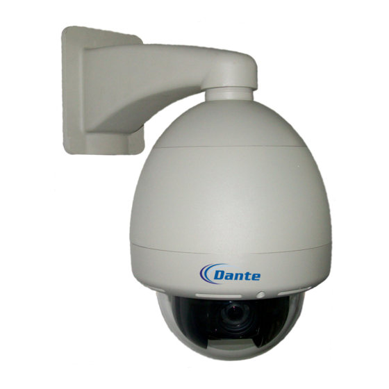
4. STRUCTURE OF HIGH SPEED DOME CAMERA (SEE PICTURE) This series of Indoor/outdoor pendent speed dome camera contains three parts. Inspect each box to make sure all parts are present. Indoor/outdoor pendent speed dome camera contains following parts: 1. Back box 2. -
Page 7: Installation Of The Speed Dome Camera
Variable self-touring speed can be set to1° ° ° ° ~ ~ ~ ~ 40° ° ° ° /second. 8 preset touring function: if the stopping time is between 5 sec and 60 sec can be set by the inside menu. 360°... -
Page 8: Specification
STEP 3 Install Dome Drive GREEN TAB RED TAB 1. Set the protocol, baud rate, dome address and camera type for the needed position. 2. Line up the integrated dome drive’s red and green tabs with the green and red labels. Push the green tab into the green label and the red tab into the red label, till both sides click into place. -
Page 9: Input Power
6.2 Rotation Index (only for Dome Drive) 360° ° ° ° continuous pan rotation Horizontal rotation 0° ° ° ° ~ ~ ~ ~ 92° ° ° ° rotation Vertical rotation Manual control speed: 0.1° ° ° ° ~ ~ ~ ~ 150° ° ° ° /sec manual operation 0.1°... - Page 10 6.4 Camera, Lens parameters (Example) Model 18×color 18× 26× 36× 36× day & night day & night day & day & SONY SONY SONY night night SONY SONY Optical Zoom Electronic Zoom Signal system PAL/NSTC 2:1 interleaved Touring System 1/4”CCD 1/4”HAD CCD >480TVL >540TVL...
- Page 11 Model 22×color 23× 35× 27× day & night day & night day & night day & night HITACHI HITACHI HITACHI HITACHI Optical Zoom Electronic Zoom Signal system PAL/NSTC Touring System 2:1 interleaved Between lines 2:1 interleaved 1/4”CCD 1/4”HAD CCD 1/4”CCD Horizontal >480TVL >540TVL...
-
Page 12: Chapter 2 Operation
Chapter 2 OPERATION 1. BASIC FUNCTION EXPLANATION After connect all wirings as the instruction and turn on the power, the dome camera will display it’s configure information. And after configuration is done, the menu will show configure OK information. If the user sets the POWER UP DONE, the dome will execute this movement and the tips information disappear;... - Page 13 there are 1200, 2400, 4800, 9600 four baud rate for different dial switch. N.8.1 means no verify, 8 data byte, 1 dwell position. After the dome finish configure, the user can operate the dome as the following method Operate Procedure 1.
- Page 14 Continuously press key OPEN to open iris and increase brightness IRIS OPEN gain Continuously press key CLOSE to close iris and increase IRIS CLOSE brightness gain Continuously press key NEAR, focus become near from far, the FOCUS NEAR image becomes fog from clear or becomes clear from fog. Continuously press key FAR, focus become far from near, the FOCUS FAR image becomes fog from clear or becomes clear from fog.
-
Page 15: Ptz Functions
2. PTZ FUNCTIONS This series of high-speed dome camera manual pan speed 0.1 º -150 º/second, manual tilt speed 0.1 º ~100 º/second. Pan/tilt speed and lens zoom is proportional, darker the lens zoom, slower the speed is! The current position of P, T, Z three orientations (presetting positions) can be stored and repeat use. -
Page 16: Menu Explanation
Manually operate FAR or NEAR focus adjustment can also adjust focus. The dome camera will recover auto focus adjustment function if operate horizontal, vertical rotation or control lens zoom. 3.11AUTO IRIS FUNCTION The camera automatically adjusts iris to keep normal brightness in auto iris mode. Manually operate OPEN or CLIOSE iris adjustment button can also adjust iris. - Page 17 3. when press “OPEN” key, the cursor becomes” ” ” ” ★ ★ ★ ★ ”, then can use “UP or DOWN” key to amend the parameter; press OPEN key when finish your amendment. <SYSTEM INFORMATION> 5.1 MAIN MENU <DOME SETTING> <SYSTEM INFORMATION>...
- Page 18 Ⅰ Ⅰ Ⅰ Ⅰ CAMERA 5.4 THIRD MENU AUTO FOCUS 5.4.1 CAMERA MENU Ⅰ Ⅰ Ⅰ Ⅰ ZOOM LIMIT X276 AUTO FOCUS ZOOM SPEED MEDIUM ZOOM LIMIT AUTO SHARPNESS AUTO ZOOM SPEED SHARPNESS LEVER AUTO SHARPNESS AUTO WHITE BALANCE SHARPNESS LEVER R GAIN AUTO WHITE BALANCE B GAIN...
- Page 19 BACKLIGHT COMP (BLC): ON& OFF, default setting is OFF DAY/NIGHT MODE (only for SONY-FCB480, SONY-FCB980, HITACHI VK-S454): AUTO& MANUAL, default setting is AUTO DAY/NIGHT (only available when DAY/NIGHT MODE IS MANUAL): DAY COLOR& NIGHT B&W, default setting is AUTO Ⅰ Ⅰ Ⅰ Ⅰ PANTILT 5.4.3 PAN&...
- Page 20 PATTERN 12 classes, default setting is NONE. POWER UP TIME: 1~10 minutes, default setting is10. LINE SYNC 5.4.6 LINE SYNC LINE SYNC LINE SYNC LINE SYNC PHASE LINE SYNC PHASE BACK LINE SYNC: ON & OFF, default setting is OFF LINE SYNC PHASE: 0~359, default setting is 0 ALARM 5.4.7 ALARM INPUTS...
-
Page 21: Dial Switch Setting
6. DOME CAMERA DIP SWITCH SETTING 6.1 DOME CAMERA CONTROL Note: When one control bus controls several (more than 2) dome cameras, it needs merging a 120ohm resistance at anode& cathode Com RS-485 in the farthest dome camera in order to ensure the normal work of control signal. - Page 22 6.3 Switch setting for SW2 SW2 is used to set camera address) Protocol P addresses setting: Switch2 setting Address SW2-1 SW2-2 SW2-3 SW2-4 SW2-5 SW2-6 SW2-7 SW2-8 ----- ---- ---- ---- ----- ---- ---- ---- ----...
- Page 23 Protocol D address setting: Switch2 setting Address SW2-1 SW2-2 SW2-3 SW2-4 SW2-5 SW2-6 SW2-7 SW2-8 ---- ---- ---- ---- ---- ---- ---- ----...
-
Page 24: Appendix Ⅰ Ⅰ Ⅰ Ⅰ
Appendix Ⅰ Ⅰ Ⅰ Ⅰ 1 1 1 1 .P control protocol 1). Command format BYTE VALUE FUNCTION STX(start transmission) $00 to $FF Address Data byte 1 Data byte 2 Data byte 3 Data byte 4 ETX(end transmission) $00-$FF Check sum (XOR 1-7 bytes) 2).Instruction command Bit number Data 1... - Page 25 Set aux. xx 01 to 08 Clear aux. xx 01 to 08 Pattern start Pattern stop Run pattern Start Sequence prepos Insert prepos Prepos number stack Delete prepos from Prepos number stack Clear seq. Stack Show seq. Stack Sequence dwell (0-255)second time Home function...
- Page 26 Ⅱ Ⅱ Ⅱ Ⅱ .PELCO D control protocol 1). Command format: BYTE VALUE FUNCTION STX (start transmission) $01 TO $1F Address Data byte 1 Data byte 2 Data byte 3 Data byte 4 $00-$FF Checksum(add byte 2,3,4,5,6) 2). Instruction command: Bit number Data1 Iris...
-
Page 27: P Protocol
3. RS-485 CONTROL AND FEEDBACK DATA PROTOCOL (1). Pan & tilt angle calculation ● ● ● ● Pan: 360 continuous rotation, divide into 2000 steps, each step 0.18 ; each step divide into 60 . so pan precision is ± ± ± ± 0.003 micro steps, each micro step 0.003 ●... -
Page 28: Target Angle Control Communication Protocol
4. TARGET ANGLE CONTROL COMMUNICATION PROTOCL (1). P protocol angle control extend command ① ① ① ① Pan target angle control ADDR PDMS PDSL PDSH A0h: frame start ADDR: camera address PDMS: pan target micro step (range: 0-59) 91H: pan target angle control code PDSL: pan target step low byte PDSH: pan target step high byte (range: 0-1999) Afh: frame stop... -
Page 29: Appendix Ⅱ Ⅱ Ⅱ Ⅱ Troubleshooting
② ② ② ② Tilt target angle control ADDR TDMS TDSL TDSH A0h: frame start ADDR: camera address TDMS: tilt target micro step (range: 0-59) 93H: tilt target angle control code TDSL: tilt target step low byte TDSH: tilt target step high byte (range: 0-1999) CS: checkout sum, 1-7 NOTE: The minimum interval between two commands is: 200ms ③... -
Page 30: About Control
2. Control Ask: the single dome camera cannot be controlled by keyboard or other control equipments? → → → → First check if control line RS-485 is well connected to designed position with right direction. Then check the control equipment and dome control protocol, baud rate and address. If it still can not be controlled, use elimination to check whether the control equipments or camera has troubles. - Page 31 → → → → Normally, the power wires have some resistance. There is some loss during voltage transmission. The longer the wire is and the smaller the wire diameter is, the worse loss will be. Please refer to following wire diameter and distance requirement in order to avoiding the abnormal work caused by insufficient voltage.