Table of Contents

Related Manuals for Dante DLM1772Y


Summary of Contents for Dante DLM1772Y
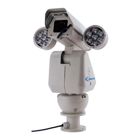
- Page 1 DLM1772Y-DLM1775Y Integrated Camera Positioning w/Dual IR Lamps Installation and Operations Manual Model Number: DLM1772Y-DLM1775Y Description: Integrated Camera Positioning System With dual IR Lamps and Day/Night 23x, 26x, 36x Zoom...
-
Page 2: Table Of Contents
Table of Contents DLM1772Y-DLM1775Y with dual IR Lamps page 1. Installation 1.1 Foreword 1.2 Safeguards 1.3 Function & Features 1.4 Pedestal Installation Wiring Diagram Mechanical Diagram and IR Lamp Specifications 1.5 Wall Installation Wiring Diagram 1.6 Technical Parameters 1.6.1 Structure Mechanical Diagram 1.6.2 Rotating... -
Page 3: Installation
1. INSTALLATION MANUAL 1.1 FOREWORD This manual introduces the function, installation and operation of the integrated high speed pan tilt camera in details. Please thoroughly familiarize yourself with the information in this manual prior to installation. This series pan tilt camera is specially designed for airports, homeland security, customs, highway etc. -
Page 4: Pedestal Installation
Change speed proportionally - Pan/tilt speed and the depth of zoom lens decline proportionally 128 preset position, with accuracy error less than 0.1 Preset target speed: 150 /sec for pan, 80 /sec for tilt Manual control speed: 0.1~100 /sec for pan control, 0.1~80 /sec for tilt Alterable auto scan speed: 1 /sec may be set by the in-built menu... - Page 5 Steps of pedestal installation: STEP 1 Locate the floor or impending base level that may support 4 times the weight of pan tilt. Fix the screws provided on the floor or firm surface. STEP 2 fix the pedestal on the floor or impending base level: STEP 3 Install power supply, video output, RS-485 control input wiring through waterproof connector plugs, and connect them to the corresponding power supply, video,...
-
Page 6: Wiring Diagram
Connect the cable according to the following pinout diagram: STEP 4 Loosen the four Φ3mm screws on the fixed rotating platform and remove the transformer fixed board module from the rotating platform. There are four installation holes under the rotating platform. Fix the four Φ5x10 fixed screws on the pedestal, then install the connecting cable into the pedestal and screw it with waterproof BNC plugs. -
Page 7: Mechanical Diagram And Ir Lamp Specifications
DLM1778 Pedestal Mount * Inverted View of mount * Maximum Bearing Weight 100Kg * Aluminum alloy material 1. Rubber Gasket for top of pole 2. Cable Gland cover 3. Top of mount for installing DLM1778 Integrated camera system Dimensional Drawing: (unit: MM) DLM1778 Pedestal Mount IR Lamp Specifications Distance:... -
Page 8: Wall Installation
1.5 WALL INSTALLATION The wall installation camera contains following parts. Inspect each package to make sure all parts are present. Integrated pan tilt rotating platform wall bracket Integrated pan tilt 1 pc Rotating platform(with connect cables) 1 pc pedestal 1 pc wall bracket 1 pc connecting cables... - Page 9 STEP 2 Install the power supply box on the wall if power supply box is required, then install the wall bracket on the power supply box. If no power supply enclosure is needed, install the bracket directly on the wall. STEP 3 Install power supply, video output, RS-485 control input wiring through the body of the bracket and connect them to the corresponding power supply, video, RS-485 wiring of the cable provided.
- Page 10 STEP 5 Installing the platform - Loosen the four Φ3mm screws on the fixed rotating platform and remove the transformer fixed board module from the rotating platform. There are four installation holes under the rotating platform. Check the cables connecting and put them into bracket. Install the four Φ5×10 fixed screws on the pedestal.
-
Page 11: Technical Parameters
1.6 TECHNICAL PARAMETERS 1.6.1 Structure parameters: Integrated pan tilt Aluminum alloy Rotating platform Aluminum alloy Bear weight mode top bear standard bear weight Shield module with housing, defrost device, heater and fans installation wall mount, pedestal mount bracket requirement 4 times of the pan tilt’s weight operating temperature -40ºC ~ 50ºC Dimension... -
Page 12: Camera
1.6.4 camera, lens parameters DLM1972 - 23X Day/Night DLM1972 - 26X Day/Night DLM1975 - 36X Day/Night Camera Specifications Image Sensor ¼” Hitachi CCD ¼” SONY CCD ¼” SONY CCD Resolution 480/550BW TVL 480/570BW TVL 540/650BW TVL Effective Pixels NTSC 380k / PAL 450k NTSC 630k / PAL 740k NTSC 380k / PAL 440k Signal Format... -
Page 13: Operation Procedures
VERSION 1.10 When configuring: PROTOCOL ADDRESS COMM 2400. N.8.1 CONFIGURING VERSION 1.10 PROTOCOL ADDRESS COMM 4800. Configure OK: N.8.1 CONFIGURE OK P:000/T:00 NOTE: 1. VERSION 1.10 is the software version number of the P/T camera, and it will change as the product’s upgrade. 2. - Page 14 STOP SCAN Preset 96 (hit“9”+“6”+ “Preset”) PRESET TOUR Preset 98 (hit“9”+“8”+ “Preset”) AUTO SCAN Preset 99 (hit“9”+“9”+ “Preset”) ZOOM WIDE 1. Press the ZOOM WIDE button or turn the joystick clockwise until the image is acceptable 2. Release the button or joystick ZOOM TELE 1.
-
Page 15: Ptz Functions
2. 2 PTZ FUNCTIONS This series high-speed P/T camera manual pan speed 0.1 º -100 º/second, manual tilt speed 0.1º ~ 80º/second. Pan/tilt speed and lens zoom is proportional, darker the lens zoom, slower the speed is! The current position of P, T, Z three orientations (presetting positions) may be stored and repeat use. -
Page 16: Auto Iris
3.11 Auto iris function The camera automatically adjusts iris to keep normal brightness in auto iris mode. Manually operate OPEN or CLOSE iris adjustment button may also adjust iris. The P/T camera will recover auto adjustment function if operate horizontal, vertical rotation or control lens zoom. -
Page 17: Second (Screen) Menu
SYSTEM INFORMATION 5.2 SECOND MENU I CAMERA TYPE P/T TYPE COMM 4800、N、8、1 COMM PROTOCOL ADDRESS PROTOCOL VERSION 1.10 ADDRESS VERSION AUTO EXIT TIME AUTO EXIT TIME BACK BACK NOTE: Except “AUTO EXIT TIME”, items may not be modified only displayed in the menu. 5.3 CAMERA MENU I CAMERA AUTO FOCUS... - Page 18 STABILIZER Default Setting: OFF Stabilizer Mode: ON and OFF, Camera with this function displays in menu Default Setting: OFF WDR Model (for 23X HITACHI VK-S454): ON and OFF, it works when the backlight compensation is OFF. <NEXT> 5.3.1 CAMERA MENU II AUTO IRIS AUTO AUTO IRIS...
-
Page 19: Pan/Tilt Menu
5.4 PAN/TILT MENU PAN/TILT AUTO FLIP AUTO FLIP PROPORTIONAL PAN PROPORTIONAL PAN PARK ACTION NONE PARK ACTION PARK TIME 30min PARK TIME PRESET TOUR TIME PRESET TOUR TIME SCAN SPEED 10d/s MANUAL STOPS SCAN SPEED SCAN STOPS MANUAL STOPS ANGLE DISPLAY ANGLE DISPLAY SET AZIMUTH ZERO SET AZIMUTH ZERO... -
Page 20: Powering Up
5.5 POWERING UP ACTION POWER UP POWER UP ACTION NONE POWER UP ACTION POWER UP TIME 2min POWER UP TIME BACK BACK POWER UP ACTION Default Setting: NONE Power Up Action Mode: NONE, 1PRESET~8PRESET, SCAN, PRETOUR, PATTERN selectable. POWER UP TIME Default Setting: 2minutes Power Up Time may be selected from 2s to 10s 5.6 LINE SYNC... -
Page 21: Auxiliary
5.8 AUXILLIARY AUX1 MODE WIPER AUX2 MODE INFRARED BACK BACK WIPER Default Setting: OFF Wipe input is relay input, the mode: ON and OFF INFRARED Default Setting: OFF Infrared input is relay input, the mode: ON and OFF 5.9 RESET CAMERA. When users choose this item, camera will reset to the default setting. -
Page 22: Switch Sw2 Receiver/Driver Settings
6.3 Switch setting for SW2 Note: Switch SW2 is used to set receiving address. Protocol P addresses setting: Switch setting Address SW2- SW2- SW2- SW2- SW2- SW2- SW2- SW2- ----- ---- ---- ---- ----- ---- ---- ---- ----... - Page 23 Protocols D address setting: Switch setting Address SW2-1 SW2-2 SW2-3 SW2-4 SW2-5 SW2-6 SW2-7 SW2-8 ---- ---- ---- ---- ---- ---- ---- ----...
-
Page 24: Appendix A Troubleshooting
Appendix A TROUBLESHOOTING 1. Image Problem: No image displayed on monitor? →First check if the power supply wire connection, voltage, indicator and P/T camera work well, and then check the video wires, or it may be a problem with the cam module. Problem: Image becomes black after self check, but may be controlled →Control system may have changed the camera iris parameters. -
Page 25: Installation
→DVR control protocol is not compatible with the product or the function is not complete. Problem: why does the same pan tilt have different control speeds at different hard disk video recorder? →Speed command codes in control software of DVR are different. Problem: DVR may not control speed of pan tilt →Control command code of control software in DVR only has a fixed speed.
Need help?
Do you have a question about the DLM1772Y and is the answer not in the manual?
Questions and answers