
Related Manuals for Dante DLS1798LA3P9S


Summary of Contents for Dante DLS1798LA3P9S
- Page 1 DLS1798LP Thermal PTZ Camera Installation and Operations Manual Model Number: DLS1798LA3P9S - NTSC DLS1798LB3P9S - PAL Description: Thermal and 36x CCD PTZ Camera...
- Page 2 DLS1798LA-B3P9S Intelligent PTZ Thermal Imaging System User Operation Manual Thank you for using our company’s product. Please read this operation manual carefully before using it, as it may provide User with correct technical information on how to properly do the installation. Please contact us if User comes across problems that are not mentioned in this instruction.
- Page 3 5. Do not open the device by yourself, or else it may cause electric shock or machine damage. If there are problems, please contact factory and remember not to try and repair it without instructions from Dante. 6. In order to protect the device and people, this device need to be installed on firm, flat area.
-
Page 4: Table Of Contents
Content Part One Introduction ......................1 1.Introduction ........................1 2.Features ........................1 3.Technical Indicators ...................... 2 Part Two Installation Instruction..................3 1.Installation Environment ....................3 2.Shape and dimension ....................4 3.Installation step ......................4 4.System connection reference ..................7 Part Three Operation Introduction .................. -
Page 5: Part One Introduction
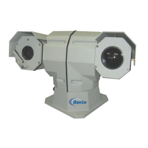
Part One Introduction 1. Introduction This thermal imaging camera combines thermal imager, visible camera and pan-tilt. Unit has two video output and 360°horizontal pan rotation for high end monitoring 2. Features DLS1798 adopts thermal imaging technology and has a clear image, not restricted by light low light color to black and white camera for continuous monitoring day and night... -
Page 6: Technical Indicators
3.Technical Indicators Night vision 800m-2Km Effecting Distance Day vision 1000m Sensor 1/4″ Exview HAD CCD Valid pixel 440,000 TV Line 550TVL(color) ;570TVL(black & white) 3.4~122.4 mm,36x optical zoom Focal length Iris F1.6~F4.5 Camera 57.8°(wide)~1.7°(telephoto) Focus Auto/Manual/Zoom trigger Lowest illumination 0.2Lux/F1.49( color); 0.001Lux/F1.4( black & white ) White balance Auto,ATW,Indoor,Outdoor,One-push,Manual ≥50db... -
Page 7: Part Two Installation Instruction
Part Two Installation Instruction 1.Installation Environment Before installation, please check if the environmental temperature, humidity, cleanliness, radio frequency, surge protection; be sure it meets the requirements, check if the power supply is safe. (1) Anti-static Keep suitable temperature and humidity conditions (2) radio frequency Keep the night vision camera far away from the radio transmitters, radar transmitters and other high-frequency devices... -
Page 8: Shape And Dimension
2.Shape and dimension Night vision camera’s shape and dimension (mm) 3.Installation step a.Remove the thermal camera’s bottom plate b.Adjust the dip switch (according to the address set up instruction) to set up the address (connect the camera to the resistor) c.Re-install the bottom plate;... - Page 9 Fixing Layout After installation, please connect the aviation plug pinout according to the definition below, then connect to the device. Definition as follows: Power supply, control signal input, video signal output all connect with one cable with 12 PINS. See below:...
- Page 10 twelve-hole aviation outlet pin definition: Definition Remark Video 1+ Video 1 Output + Video 1- Video 1 Output - 24VAC: black (thick) 24VAC power input RS422Y: red (thin) 422 control Y RS422B-: yellow 422 control B 24VAC: red (thick) 24VAC power input RS422Z: black (thin) 422 control Z RS422A: orange...
-
Page 11: System Connection Reference
4.System connection reference Thermal camera should be connected with other equipment to form a system. The following is the simple sketch:... -
Page 12: Part Three Operation Introduction
Part Three Operation Introduction 1.Function Introduction 1.Thermal image system a. It adopts passive thermal imaging technology, imaging clearly, excellent hiding feature, not restricted by light source. b. Thermal Camera may be set up via menu, to change color palettes, realize zooming etc. And the settings will not be lost when power off. c. -
Page 13: Menu Setup Instruction
3.Integrated full range pan-tilt a. Pan rotate 360º, tilt rotate -90º~90º b. Pan rotate may realize 0~50°/s continuous shift adjust, tilt rotate may realize 0~50°/s continuous shift adjust c. Low speed steady rotate, little noise, clear and steady image d. Reach full range no spot monitoring, exact orientation be ±0. 1°. 4.High Intelligence a. - Page 14 item that need set, turn it left or right to amend the contents or enter this item to set; If use matrix, operate “ ”.“ ” to move cursor to the item that need TILT UP TILT DOWN set, operate “ ”.“...
- Page 15 2.2.2 ID POS:Set the address position. The address may be displayed at the four corners of the screen: TOP-L (top left), TOP-R (top right), BOTT-R (bottom right), BOTT-L (bottom left). 2.2.3 TITLE DIS:If this item is ON, the screen will show the title of pre-setting point when User adjusts the pre-setting point.
- Page 16 2.3.4 IRIS:setup automatic iris, AUTO. 2.3.5 D-ZOOM:set digital zoom. ON / OFF. FOCUS : setup automatic focus. AUTO–automatically control / 2.3.6 MANU–manual. 2.3.7 WB SET:white balance setup. ATW / INDOOR / OUTDOOR / ONEPUSH / AUTO / MANU 2.3.8 MENU OF CAM:this item is empty. 2.3.9 RETURN:return to the main menu.
- Page 17 take effect, remember to setup the AUTO HOME in HOME POS may be “ON”. from pre-setting point 1-50. 2.4.2.3 DWELL TIME:Setup the automatic return time, which means how long it will return to HOME without control. The time may be set from one minute to 99 minutes.
- Page 18 RAIN。 Setup thermal camera switch among normal 2.5.8 DZOOM: size/2X/magnification. Under condition of both exit menu for CCD camera and thermal camera, press OPEN switch between 1X/2X; press CLOSE switch among WHITE/BLACK/PSEUDO COLOR. Under no menu condition, press NEAR/FAR to realize thermal lens manual focus.
- Page 19 key-press to leave the edit state. The operation under the edit state please refers to the back. RUN PATROL:Run patrol function. Use PAN LEFT/PAN RIGHT to 2.6.6 choose paths number, push OPEN key-press to run and exit. 2.6.7 RECORD PATTERN:Edit tracking self-inspection, may remember at most 40 seconds PTZ operation.
-
Page 20: Protocol And Address Setting
Presets title edit operation After User enters the edit state, the screen will PRESET : : : : NO. 001 TITLE : : : : NO TITLE show as the picture: User may see that the current setup is No.1 CLOSE:... - Page 21 Power Supply Circuit Board DIP: State of Dip Switch DIP-1 DIP-2 DIP-3 DIP-4 DIP-5 DIP-6 DIP-7 DIP-8...
- Page 22 … … Using J1 former eight dips to set up the camera’s address, ranges from 0~255. DIP-1 to DIP-8 means a eight binary, DIP-8 means the highest bit, DIP-1 means the lowest bit. Some address shown as below: 2.Baud Rate Setting:Using J1 DIP 9 and DIP10 to set up the baud rate, 2400bps.4800bps.9600bps.19200bps optional.
-
Page 23: Part Four Quality Guarantee And After-Sales Service
Part Four Quality guarantee and after-sales service Warranty and Service Dante Security warrantees product for 12 months from date of Customer receipt of equipment. Extended warranty is available from factory. Please contact support@dantesecurity.net or Sales@dantesecurity.net Appendix I: Common Problems Analysis... -
Page 24: Appendix Ii : Rs 485 Line
Appendix II : RS 485 LINE RS485 Features RS485 standard is communication line of special impedance 120Ω, and support 32 node at most, including controlling and controlled equipments. RS485 Transmission Distance 0.56mm(24AWG)twisted pair line as communication line Baud Rate Farthest Transmission Distance 2400 Bps 1800m... - Page 25 4. Configurations Customers often uses Star configuration in cases, and terminal resistance must connect farthest two devices. As following sketch, 1 # and 15 #are not compatible with RS485, it result to signal reflection and anti-jamming ability reduction. Regarding this problem, we recommend to use RS485 Divider, which may change Star Chain to suitable connection way, and avoid problems to promote communication.
-
Page 26: Appendix Iii: Cable Spec List All Countries
Appendix III: Cable Spec List all countries Metric System Section Square American Standard Britain Standard ( ( ( ( mm) ) ) ) ( ( ( ( mm ) ) ) ) 0.050 0.00196 0.060 0.00283 0.070 0.00385 0.080 0.00503 0.090 0.00636 0.100...
Need help?
Do you have a question about the DLS1798LA3P9S and is the answer not in the manual?
Questions and answers