
Related Manuals for Dante DLS1798LA3Q9


Summary of Contents for Dante DLS1798LA3Q9
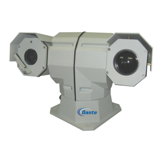
- Page 1 DLS1798LA3Q9 Thermal PTZ Camera Installation and Operations Manual Model Number: DLS1798LA3Q9 Description: Thermal and 36x CCD PTZ Camera...
- Page 2 DLS1798LA3Q9S PTZ Thermal Camera User Operation Manual Thank you for using our company’s product. Please read this operation manual carefully before using it, as it can provide you with correct technical information on how to properly do the installation. Please contact us if you come across problems that are not mentioned in this instruction.
- Page 3 5. Do not open the device by yourself, or else it may cause electric shock or machine damage. If there are problems, please contact factory and remember not to try and repair it without instructions from Dante. 6. In order to protect the device and people, this device need to be installed on firm, flat area.
- Page 4 Contents Part One Introduction ..................1 1. Introduction .................... 1 2. Features ....................1 3. Technical Indicators ................1 Part Two Installation Instruction ..............8 1. Installation Environment ................ 8 2. Shape and Dimension ................9 3. Installation Step ..................9 4.
-
Page 5: Part One Introduction
Part One Introduction 1. Introduction This thermal imaging camera combines thermal imager, visible camera and pan-tilt. Unit has two video output and 360°horizontal pan rotation for high end monitoring 2. Features DLS1798 adopts thermal imaging technology and has a clear image, not restricted by light low light color to black and white camera for continuous monitoring day and night... - Page 6 dimension 507*310*254mm MTBF(Mean Time Between ≥10000 hours Failure) Working -25℃~+ 60 ℃ temperature Storage -40℃~+ 85 ℃ Environment temperature indicators Anti-vibration 150m/s² 11ms continuously spray fog for 48 hours under Salt-fog proof PH6.5-7.2 3.2 Key Components Indicators Scanning method Progressive Scan zoom 36X optical zoom Image inductor...
-
Page 7: Menu Basic Operation
4. Menu Setup Instruction 1. Menu basic operation Use keyboard or matrix to adjust No. 64 pre-sets or adjust the No.1 pre-sets twice within four seconds, the main menu will be open. After the menu is on the screen, if use keyboard, you can control joystick to move cursor, turn up or down to move cursor to the item that need set, turn it left or right to amend the contents or enter this item to set;... - Page 8 DISPLAY SETUP = = = = = = = = = = = = = = = = ID DISPLAY ID POS TOP-L TITLE DIS PRESET POS CAM DISPLAY CROSS DIS GRID DIS PT ANGLE RETURN 2.2 DISPLAY SETUP 2.2.1 ID DISPLAY: When this item is ON, the screen will show the address ID of thermal camera, for example, “CAM 006”.
- Page 9 2.3.5 D-ZOOM: Set digital zoom, ON / OFF. 2.3.6 FOCUS: Setup automatic focus. AUTO–automatically control / MANU–manual. Note: when FOCUS is in the status of MENU, press "Focus Near "or "Focus Far" can realize manual focus of camera; Exit the menu, press Near or Far can realize manual focus of thermal imaging.
- Page 10 2.4.4 WIPER: Wiper control item, with wiper mode, controls the wiper to move once or continuously. 2.4.5 WIPER MODE: you can choose the single mode or continuous mode, the default is continuously mode. 2.4.6 RETURN: Return to the main menu. THERM IMAGE SET 2.5 THERM IMAGE SET = = = = = = = = = = = = = = = = =...
- Page 11 The operation under the edit state please refers to the back. 2.6.6 RUN PATROL: Run patrol function. Use PAN LEFT/PAN RIGHT to choose paths number, push OPEN key-press to run and exit. 2.6.7 RECORD PATTERN: It is blank. 2.6.8 RUN PATTERN: It is blank. 2.6.9 RETURN: Return to the main menu.
-
Page 12: Installation Environment
Part Two Installation Instruction 1. Installation Environment Before installation, please check if the environmental temperature, humidity, cleanliness, anti-jamming, anti-lightning etc. meet the requirements, check if the power supply is safe. 1.1 Anti-static Keep suitable temperature and humidity conditions 1.2 Anti-jamming Keep the night vision camera far away from the radio transmitters, radar transmitters and other high-frequency devices Adopts electromagnetic shield when necessary... -
Page 13: Shape And Dimension
2. Shape and Dimension Bottom dimension (mm) 3. Installation Step 3.1 Please use four M10×35 hexagon bolt and four M10 nut to fix the night vision camera onto customer’s plate. Below is the size of night vision camera’s fix hole. 3.2 After installation, please connect the aviation plug pinout well according the definition, then connect to the device, the lines’... - Page 14 Two cores aviation outlet definition shown as follows, you can also see the marks on cable. PIN NO. Definitions Cable +24V Brown -24V Blue Then please separately connect brown and blue wire to 12V-24V power supply box’s “+”, “-”output. Control and Video Output Cable Nine cores aviation outlet definition as follows;...
-
Page 15: System Connection Reference
RS-422B Yellow RS-422A Orange If using one way RS-485 interface, connect only yellow orange wires. Note: Please use bolts, nuts and shock absorber that supplied. If have to change bolts, please choose the one with right length. Please use the power supply that supplied. Or else it would cause no operation of the camera. -
Page 16: Function Introduction
Part Three Operation Introduction 1. Function Introduction 1.1 Thermal image system a. It adopts passive thermal imaging technology, with clear image, not restricted by light source. b. You can use “CLOSE” to control pseudo colors. Thermal camera will be change among HOT WHITE, HOT BLACK, PSEUDO COLORs. There are ten modes: FUSION ,... -
Page 17: Cam Protocol And Address Setting
1.4 High Intelligence a. User may save 220 preset points. b. Total 6 cruise paths: No. 1 ~ No.6 cruise paths corresponding to 250~255 presetting bits respectively, call 250~255 presetting bits can set up the cruise paths. The cruise points of No. 1 cruise path is from Presetting Bit 1~20;... - Page 18 Main Control Board Address Dip Switch DIP-1 DIP-2 DIP-3 DIP-4 DIP-5 DIP-6 DIP-7 DIP-8...
-
Page 19: Protocol Setting
… … Cam’s address is set up by using the former 8 bits of J16, and ranges from 0~255. DIP-1 to DIP-8 is equivalent to an 8-bit binary number, DIP-8 represents the highest bit, DIP-1 represents the lowest bit. Some dip switch shown as follows: 3. -
Page 20: Part Four Quality Guarantee And After-Sales Service
Part Four Quality guarantee and after-sales service 1. Quality Guarantee and After-sales Service Dante Security warrantees product for 12 months from date of Customer receipt of equipment. Extended warranty is available from factory. - Page 21 Appendix : Common Problems Analysis problem possible reason solving method the power supply is damaged Please read PS requirement thermal camera has power and may need to change no action and no sufficient image after power wrong connection of Connect according to pinout power supply line line failure eliminate...
-
Page 22: Appendix : Rs-485 Line
Appendix : RS 485 LINE 1. RS-485 Features RS-485 Industry Line is communication line of special impedance 120Ω, and support 32 node at most, including controlling and controlled equipments. 2. RS-485 Transmission Distance 0.56mm (24AWG) twisted pair line as communication line Baud Rate Farthest Transmission Distance... - Page 23 4. Problems in cases Customers often use Star Chain in cases, and terminal resistance must connect farthest two devices. As following sketch, 1 # and 15 #can’t accord with RS-485, it result to signal reflection and anti-jamming ability reduction. Regarding this problem, we recommend to use RS-485 Divider, which can change Star Chain to suitable connection way, and avoid problems to promote communication.
-
Page 24: Appendix : Cable Spec List All Countries
Appendix : Cable Spec List all countries American Metric System Section Square Britain Standard Standard (mm) (mm ) 0.050 0.00196 0.060 0.00283 0.070 0.00385 0.080 0.00503 0.090 0.00636 0.100 0.00785 0.110 0.00950 0.130 0.01327 0.140 0.01539 0.160 0.02011 0.180 0.02545 0.200 0.03142 0.230... - Page 25 1.000 0.7854 1.250 1.2266 1.500 1.7665...
Need help?
Do you have a question about the DLS1798LA3Q9 and is the answer not in the manual?
Questions and answers