
Related Manuals for Dante DLM1762


Summary of Contents for Dante DLM1762
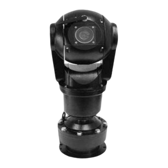
- Page 1 DLM1762-DLM1765 Rugged Integrated PTZ System Installation and Operations Manual Model Number: DLM1762-DLM1765 Description: Rugged, Shock Proof, Integrated PTZ Camera System...
- Page 2 DESCRIPTION DLM1762 and DLM1765 are NTSC and PAL Day/Night, 26X, 30X and 36X optical and 12X Digital zoom, Rugged, Shock Proof Integrated PTZ Systems that represent state-of-the art, DSP based camera technology. Units feature built-in camera module installed in Vandal Resistant, Shock, Corrosion and Waterproof Aluminum or Stainless Steel enclosure.
-
Page 3: Table Of Contents
Table of Contents DLM1762-DLM1765 Page Chapter 1:Installation manual 1.1 Preface 1.2 Appearance 1.3 Function Descriptions Chapter 2 Notice of Operation 2.1 Safety Notice 2.2 Preparation of Installation 2.3. Notice of Installation Chapter 3 Installation Guide 3.1 Pedestal mount 3.2 Wall mount Chapter 4 Technical Parameter 4.1 Structure Parameter... - Page 4 Chapter 1: INSTALLATION MANUAL 1.1 PREFACE This manual introduces the functions, installation and operation of the shock-proof integrated high speed camera in details. Please thoroughly familiarize yourself with the information in this manual prior to installation. This series integrated camera system is ideal for special occasions, such as airports, frontier defense, customs and highway etc.
-
Page 5: Function Descriptions
High reliability and the internal data will not lost after power cutoff The pan/tilt orientation display and camera zoom display Built-in function menu, the function of camera and pan/tilt can be set. Powering on state setting: can be set by in-built menu Several kinds of auto scanning mode, the speed can be set by built- in menu Functions of video freeze, WDR and BLC. - Page 6 Once you let go of the joystick after the dome rotates, joystick control returns to normal operation. The auto flip function is useful for following a person who passes directly beneath the camera. Preset Any position of dome camera PTZ can be conserved. We call it preset (pre-established position). The preset can be transferred and cleaned.
-
Page 7: Safety Notice
Chapter 2 Notice of Installation 2.1 Safety Notice Aim to guarantee user to use the product correctly and avoid danger or loss of property. Defense measure is including two parts “Warning” and “Notice” as follows: Warning: Ignoring warning may cause death or great damage. Notice: Ignoring notice may cause damage or loss of property. -
Page 8: Preparation Of Installation
the tip may cause equipment damage) Please thoroughly read this manual prior to installation and operation. 2.2 Preparation of Installation 1, Basic requirement 1) All electric working must be accorded to latest electric, fire proof and related specification. 2) Be sure all accessories are included as packing list and application and installation way are as required. If not, please contact with supplier. -
Page 9: Chapter 3 Installation Guide
Chapter 3 Installation Guide 3.1 Pedestal Mount Remark: Installation of pedestal stand mode with pitching angle 30°, pedestal reversed mode and pedestal stand mode is same. 3.1.1 Equipment list: The mode of camera contains following parts. Inspect each package to make sure all parts are present. Integrated high speed PTZ camera Power supply box Camera body... - Page 10 3.1.2 Steps of installation: Pedestal stand STEP 1 Locate the floor or impending base level that can support 5 times the weight of camera. Fix the bulgy snail Φ8mm on the floor or firm surface. STEP 2 fix the camera body on the floor or impending base level locknut...
- Page 11 STEP 3 Put power supply, video output, RS-RS-485 control input wiring through waterproof connector plugs, and connect them correspondingly to power supply, video, RS-RS-485 wiring of the connecting cable. Connect the cable refer to the following picture: Remark: Cable can be from either side or bottom. Or put the wiring through the waterproof connector plugs and joint them on the supplied 12 cores vacant connector plugs.
-
Page 12: Wall Mount
3.2 Wall Mount Remark: Installation of pedestal stand mode with pitching angle 30° and pedestal stand mode is same. 3.2.1 Equipment list: The mode of camera contains following parts. Inspect each package to make sure all parts are present. Integrated high speed PTZ camera Power supply box Wall mount bracket connecting tray Camera body... - Page 13 3.2.2 Steps of installation: Wall Pedestal stand STEP 1 Locate the wall or impending base level that can support 5 times the weight of camera. Fix the bulgy snail Φ8mm on the floor or firm surface. STEP 2 If the power supply box is needed, fix the power supply box on the wall firstly, then fix the wall bracket on the power supply box;...
- Page 14 Or put the wiring through the waterproof connector plugs and joint them on the supplied 12 cores vacant connector plugs. Tighten the waterproof connector plugs when finish connecting. STEP 4 Install the PTZ camera, insert the cables to the wall bracket, fix the bracket wall and connecting tray with 4pcs M8 x 35 outer hexangular screws, and then fix the PTZ camera with connecting tray by M8 x 30 outer hexangular screws.
-
Page 15: Chapter 4 Technical Parameter
Chapter 4: TECHNICAL PARAMETER 4.1 Structure parameter: ●Integrated dome drive: aluminum-alloy/stainless steel ●Standard weight loading: 5KG ●way of installation: pedestal mount wall mount ●the requirement for bracket: can stand more than 5 times the weight of camera ●Dimension: see the following Dimension Drawing: ●Weight (approximate) Without IR lamps one Net weight ……………………..10.5kg... -
Page 16: Rotation Index
4.2 Rotation Index: Pan rotation 360ºcontinuous rotation Tilt rotation Pedestal stand mode: -35º~+90º Pedestal stand mode with pitching 30º angle: -65º~+90º Reversed mount: +35º~-90º Manual control speed 0.1º~80º/Second manual operation Tilt 0.1º~40º/Second manual operation Preset speed 80º/ Second Tilt 40º/Second 4.3 Electrical Index Input voltage Standard 18VAC, 15VDC to 24VDC is optional... -
Page 17: Camera Module Parameter
4.4 camera module parameter: Mode 26×D/N 26x D/N (with stabilizer) 36×D/N Optical zoom Digital zoom Signal system PAL/NTSC Scan system 2:1 interlacing scan 1/4”CCD Effective Pixel 795(H)×596(V) Horizontal >480TVL >480TVL >540TVL resolution Lens focus F1.4(f=2.5-91mm) F1.4(f=2.5-91mm) F1.4(f=3.4-122.4mm) 3.4mm wide angel 57.8º, Horizontal 3.5mm wide angel 54.2º... -
Page 18: Ir Lamps Parameter
4.5 IR Lamps parameter >100m Distance Angle 45º two pairs of 7X 1W,6X Φ8 IR Lens Voltage DC12V Power 2X6W Measurement(LXWXH) two units of Φ108X 85mm Net Weight 2X 0.5kg... -
Page 19: Chapter 5 Operation
Chapter 5 OPERATION 5.1. Configure after power on After connect all wirings as the instruction and turn on the power, the camera will display its configured information. And after it finish configure, the menu will show “configure OK” information. If the user sets the POWER UP DONE, the camera will execute this movement and the tips information disappear;... -
Page 20: Basic Functions Operation
5.2 Basic Function Operation OPERATION PROCEDURE Pan/Tilt 1. To rocker control keyboard, camera will rotate to the operation direction if the rocker leans to one direction of up/down/left/right. The speed depends on the distance between rocker and center. The camera will move slowly to the operation direction if move the rocker lightly in one direction. - Page 21 becomes fog from clear or becomes clear from fog. PRESETS 1. When set presetting, press “preset No.”+ key ”PRESET”(about for 3 seconds) 2. When use presetting, press “preset No.”+ key ”PRESET” 3. Please refer to operation instruction book for controller. Wiper Control Way 1: 1, Press preset 95 to enter into OSD menu.
-
Page 22: Special Function Preset
5.3 Special Function Preset The following stipulations are for presetting, Preset() function Parking Position 180º flip lever home place Repeat to run preset 63, open or close displayed central line (Setting) display all privacy zones. (Transfer) close all privacy zone Open IR lamps Close IR lamps Open Wiper... -
Page 23: Chapter 6 Osd Operation
Chapter 6 OSD OPERATION 6.1 Operation Introduction This series high-speed camera manual pan speed 0.1 º -80 º/second, manual tilt speed 0.1 º ~40 º/second. Pan/tilt speed and lens zoom is proportional, darker the lens zoom, slower the speed is! The current position of P, T, Z three orientations (presetting positions) can be stored and repeat use. -
Page 24: Main Menu
MAIN MENU PAN/TILT CAMERA 〈SYSTEM INFORMATION 〉 〈SYSTEM INFORMATION〉 〈CAMERA 〉 〈CAMERA 〉 〈PAN/TITL 〉 〈PAN/TITL 〉 〈POWER UP〉 〈POWER UP〉 〈LINE SYNC〉 〈LINE SYNC〉 〈AUX〉 〈AUX〉 RESET CAMERA RESET CAMERA EXIT EXIT 6.3 Second Menu SYSTEM INFORMATION 6.3.1 System Menu ×18 CAMERA TYPE CAMERA TYPE... - Page 25 CAMERA AUTO FOCUS AUTO FOCUS ZOOM LIMIT ZOOM LIMIT ZOOM SPEED ZOOM SPEED SHARPNESS LEVEL SHARPNESS LEVEL BACKLIGHT COMP BACKLIGHT COMP VIDEO FREEZE VIDEO FREEZE DAY/NIGHT MODE AUTO DAY/NIGHT MODE STABILIZER STABILIZER 〈NEXT〉 〈NEXT〉 BACK BACK NOTE: The function of STABILIZER, WDR will be only available when the camera has such functions. AUTO FOCUS (ZOOM RANGE): default setting is ON ON&OFF...
-
Page 26: Camera Menu Ii
STABILIZER :default setting is:OFF There are two stabilizer modes: ON& OFF, and it only available in the menu for camera which has this function. default setting is:OFF (Only for HITACHI VK-S454 camera):ON&OFF, and it can available only when the backlight compensation setting is OFF 6.3.3 CAMERA MENU II <NEXT>... -
Page 27: Pan/Tilt Menu
There are 0~28db grade of gain for choice AUTO WHITE BALANCE: default setting is: AUTO There are two modes of auto white balance: AUTO& MAN R GAIN: default setting is:210 There are 0~255 grade red gain available only under auto white balance mode: MAN B GAIN : default setting is:157 There are 0~255 grade blue gain available only under auto white balance mode: MAN... -
Page 28: Power Up Mode
SCAN STOPS: default setting is:OFF There are two scan stops modes: ON& OFF ANGLE DISPLAY: default setting is:ON There are two modes of angle display: ON& OFF, when the setting is ON it can display pan& tilt angle and camera zoom SET AZIMUTH ZERO:... - Page 29 privacy zones display. When ZOOM X1 ALLOW closes, all privacy zones display in any zoom status. Special Circs: Under the circumstance that ZOOM x1 ALLOW and PRESET 1 ALLOW are both “ON”, all privacy zones close; when the camera moves or zooms at Preset 1, all privacy zones appear if the optical zoom is more than 1, and all privacy zones disappear if the optical zoom is less than 1.
- Page 30 6.3.6.2 EDIT PRIVACY ZONE EDIT PRIVACY ZONE <ZONE POSITION SET> <ZONE POSITION SET> ZONE HEIGHT ZONE HEIGHT ZONE WIDTH ZONE WIDTH ZONE COLOR ZONE COLOR BLACK TRANSPARENCY TRANSPARENCY BACK BACK <ZONE POSITION SET> Set privacy zone to the related zone number. Note: When it is selected, a central line appears in the image, user can change the position by moving the vertical and horizontal position.
-
Page 31: Aux Output
6.3.7 AUX OUTPUT WIPER WIPER INFRARED INFRARED BACK BACK WIPER default setting is:OFF Two outputs: ON& OFF “ON” opens, wiper operates and stops after 60secs; wiper stops when “OFF” opens within 60 sec. INFRARED default setting is:OFF Relay output: ON& OFF “OFF”... - Page 32 Appendix 1 1.1 CAMERA CONTROL Note: When one control bus controls several(more than 2)dome cameras, it needs merging a 120ohm resistance at anode& cathode Com RS-485 in the farthest dome camera in order to ensure the normal work of control signal. 1.2 Switch setting for SW1 Note: Switch SW1 is used to set protocol, camera and baud rate Protocol, camera...
- Page 34 ------- ------ ------ ------ ------- ----- ------ ------ ------ Protocols D address setting: Switch setting Address SW2-1 SW2-2 SW2-3 SW2-4 SW2-5 SW2-6 SW2-7 SW2-8...
- Page 35 ------- ------ ------ ------ ------- ----- ------ ------ ------...
- Page 36 Appendix 2: P control protocol 1. Command format BYTE VALUE FUNCTION STX(start transmission) $00 to $FF Address Data byte 1 Data byte 2 Data byte 3 Data byte 4 ETX(end transmission) $00-$FF Check sum (XOR 1-7 bytes) 2. Instruction command Bit number Data 1 Camera on...
- Page 37 Clear aux. xx 01 to 08 Pattern start Pattern stop Run pattern Start Sequence prepos Insert prepos in stack Prepos number Delete prepos from Prepos number stack Clear seq. Stack Show seq. Stack Sequence dwell time (0-255)second Home function Prepos number 10X1 sec time-out Auto-panning speed...
- Page 38 Appendix 3: PELCO D control protocol 1, Command format: BYTE VALUE FUNCTION STX (start transmission) $01 TO $1F Address Data byte 1 Data byte 2 Data byte 3 Data byte 4 $00-$FF Checksum(add byte 2,3,4,5,6) 2, Instruction command: Bit number Data1 Iris close Iris open...
-
Page 39: Appendix 4 Troubleshooting
Appendix 4 TROUBLESHOOTING 1. Image Ask: No image displayed monitor? →First check if the power supply wire connection, voltage, indicator and dome camera work well, and then check the video wires, or it may be the drive trouble. Ask: Image becomes black after self check, but can be controlled →Interference in Data control system changes the camera iris parameters. - Page 40 Ask: the provided keyboard software can control, but the DVR cannot control or only can control some? →DVR control protocol is not agreed with our company or the function is not completed. Ask: why does the same dome have different control speeds at different hard disk video recorder? →Speed command codes in control software of DVR are different.
Need help?
Do you have a question about the DLM1762 and is the answer not in the manual?
Questions and answers