Table of Contents
Advertisement
Quick Links
Advertisement
Chapters
Table of Contents

Related Manuals for IEI Technology AFL2-12A-HM65/PC-R15


Summary of Contents for IEI Technology AFL2-12A-HM65/PC-R15
- Page 1 AFL2-12A-HM65 Series Panel PC MODEL: AFL2-12A-HM65 Series Flat Bezel Panel PC with 2nd generation Intel® Core™ i7/i5/i3 or Celeron® CPU, Wi-Fi, Touchscreen, RFID Reader, GbE LAN, RS-232/422/485, Camera, RoHS User Manual User Manual Page I Rev. 1.51 - April 23, 2018...
- Page 2 AFL2-12A-HM65 Series Panel PC Revision Date Version Changes April 23, 2018 1.51 Add Appendix B: Barebone Version Installation December 6, 2016 1.50 Updated for R15 April 8, 2014 1.12 Modified viewing angle information. August 8, 2013 1.11 Added information of the CPU temperature alert LED in Section 1.2.1.
- Page 3 AFL2-12A-HM65 Series Panel PC Copyright COPYRIGHT NOTICE The information in this document is subject to change without prior notice in order to improve reliability, design and function and does not represent a commitment on the part of the manufacturer. In no event will the manufacturer be liable for direct, indirect, special, incidental, or consequential damages arising out of the use or inability to use the product or documentation, even if advised of the possibility of such damages.
- Page 4 AFL2-12A-HM65 Series Panel PC Safety Instructions Warning! Read the user manual before connecting the system to the power source. Vorsicht! Bitte lesen Sie die Bedienungsanleitung, bevor Sie das System an eine Stromquelle anschließen. Attention! Avant de brancher le système à la source d'alimentation, consultez le mode d'emploi.
- Page 5 AFL2-12A-HM65 Series Panel PC Warning! Use only the adapter and power cord approved for this system. Use of another type of adapter may risk fire or explosion. Please refer to the user manual for the power adapter specifications. Vorsicht! Nur zugelassene Netzteile und Netzkabel dürfen verwendet werden. Die Benutzung von anderen Netzteilen kann einen Brand oder eine Explosion zur Folge haben.
- Page 6 AFL2-12A-HM65 Series Panel PC Manual Conventions WARNING Warnings appear where overlooked details may cause damage to the equipment or result in personal injury. Warnings should be taken seriously. CAUTION Cautionary messages should be heeded to help reduce the chance of losing data or damaging the product.
-
Page 7: Table Of Contents
AFL2-12A-HM65 Series Panel PC Table of Contents 1 INTRODUCTION ......................1 1.1 O ......................... 2 VERVIEW 1.1.1 Model Variations ....................3 1.1.2 Features ......................3 1.1.3 Applications....................... 3 1.2 F ......................4 RONT ANEL 1.2.1 LED Indicators ....................4 1.2.2 Function Keys....................7 1.3 R ...................... - Page 8 AFL2-12A-HM65 Series Panel PC 2.7.1.1 ATX Power Mode (Default) ..............18 2.7.1.2 AT Power Mode ..................18 2.7.2 Power Adapter ....................18 3 UNPACKING ......................19 3.1 U ......................20 NPACKING 3.2 P ......................20 ACKING 3.3 O ..................... 22 PTIONAL TEMS 4 INSTALLATION ......................
- Page 9 AFL2-12A-HM65 Series Panel PC 5.2 A ..................51 STATIC RECAUTIONS 5.3 T ..................... 52 URN OFF THE OWER 5.4 O ..................... 52 PENING THE YSTEM 5.4.1 Removing the Back Cover ................52 5.4.2 Removing the Internal Aluminum Cover ............53 5.5 R ..................
- Page 10 AFL2-12A-HM65 Series Panel PC 6.7 S ........................ 90 ECURITY 6.8 S & E ......................92 7 SOFTWARE DRIVERS ..................... 94 7.1 A ....................95 VAILABLE RIVERS 7.2 D ....................96 RIVER OWNLOAD A REGULATORY COMPLIANCE ................98 B BAREBONE VERSION INSTALLATION ............103 C INTERFACE CONNECTORS ................
- Page 11 AFL2-12A-HM65 Series Panel PC List of Figures Figure 1-1: AFL2-12A-HM65 Flat Bezel Panel PC ................ 2 Figure 1-2: AFL2-12A-HM65 Front View ..................4 Figure 1-3: LED Indicators ......................5 Figure 1-4: Function Keys ......................7 Figure 1-5: AFL2-12A-HM65 Rear View ..................8 Figure 1-6: AFL2-12A-HM65 I/O Interface Panel ................
- Page 12 AFL2-12A-HM65 Series Panel PC Figure 4-20: D-sub 9 Serial Port Connector ................44 Figure 4-21: Ethernet Connector ....................45 Figure 4-22: RJ-45 Serial Port Connector .................. 45 Figure 4-23: RS-422/485 Serial Port .................... 46 Figure 4-24: RS-422/485 Cable ....................46 Figure 4-25: D-sub 9 Connector ....................
- Page 13 AFL2-12A-HM65 Series Panel PC List of Tables Table 1-1: Model Variations ......................3 Table 1-2: LED Indicators ......................6 Table 1-3: Function Key Descriptions ..................7 Table 1-4: System Specifications ....................11 Table 4-1: Ethernet Connector Pinouts ..................44 Table 4-2: RS-422/485 Serial Port Pinouts ................. 46 Table 4-3: D-sub 9 Connector Pinouts ..................
-
Page 15: Introduction
AFL2-12A-HM65 Series Panel PC Chapter Introduction Page 1... -
Page 16: Overview
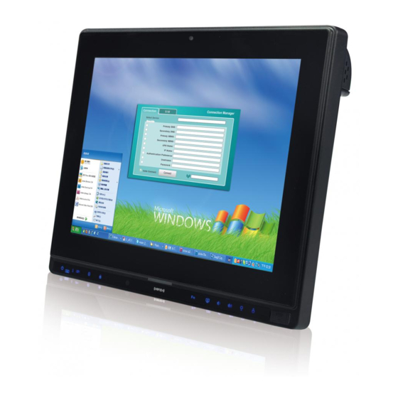
AFL2-12A-HM65 Series Panel PC 1.1 Overview Figure 1-1: AFL2-12A-HM65 Flat Bezel Panel PC The AFL2-12A-HM65 is a 2 generation Intel® Core™ i7/i5/i3 or Celeron® processor powered flat bezel panel PC with a rich variety of functions and peripherals. The AFL2-12A-HM65 is designed for easy and simplified integration into kiosk and point-of-sales (POS) applications. -
Page 17: Model Variations
AFL2-12A-HM65 Series Panel PC 1.1.1 Model Variations The model variations of the AFL2-12A-HM65 Series are listed below. Model No. Touchscreen Type AFL2-12A-HM65/PC-R15 Projected capacitive 5-wire resistive AFL2-12A-HM65/R-R15 Table 1-1: Model Variations 1.1.2 Features The AFL2-12A-HM65 features are listed below: ... -
Page 18: Front Panel
AFL2-12A-HM65 Series Panel PC 1.2 Front Panel The front side of the AFL2-12A-HM65 is a flat bezel panel TFT LCD screen surrounded by an ABS/PC plastic frame. Figure 1-2: AFL2-12A-HM65 Front View 1.2.1 LED Indicators There are fifteen LED indicator lights located along the front of the LCD screen (Figure 1-3). -
Page 19: Figure 1-3: Led Indicators
AFL2-12A-HM65 Series Panel PC Figure 1-3: LED Indicators The descriptions of each LED indicator are listed below. LED Indicator Description Shows power on/off status. Power Shows the power mode status. Controlled by the AT/ATX AT/ATX Mode power mode switch. BLUE: CPU temperature is normal. CPU Temperature Alert RED: CPU core temperature reaches TJ Max. -
Page 20: Table 1-2: Led Indicators
AFL2-12A-HM65 Series Panel PC LED Indicator Description Audio Volume Down Audio Volume Up Brightness Down Brightness Up Table 1-2: LED Indicators WARNING: When the CPU’s core temperature reaches TJ Max, the CPU temperature LED turns red and the CPU starts to lower its clock speed. At this moment, the user must lower the environments temperature or close some running applications to cool down the CPU. -
Page 21: Function Keys
AFL2-12A-HM65 Series Panel PC 1.2.2 Function Keys The function keys are located under the bottom right hand corner of the LCD screen (Figure 1-4). Figure 1-4: Function Keys The function keys are described in Table 1-3: Key Combination Function Key Description Fn + LCD On/Off RFID Enable/Disable Audio Mute... -
Page 22: Rear Panel
AFL2-12A-HM65 Series Panel PC 1.3 Rear Panel The rear panel provides access to the HDD bay and the retention screw holes that support the VESA mounting. Refer to Figure 1-5. Figure 1-5: AFL2-12A-HM65 Rear View 1.4 I/O Interface Panel The I/O interface panel located on the bottom of the AFL2-12A-HM65 has the following features: ... -
Page 23: Figure 1-6: Afl2-12A-Hm65 I/O Interface Panel
AFL2-12A-HM65 Series Panel PC 1 x AT/ATX Switch 6 x Function Keys The external I/O interface connector panel is shown in Figure 1-6. Figure 1-6: AFL2-12A-HM65 I/O Interface Panel Page 9... -
Page 24: System Specifications
AFL2-12A-HM65 Series Panel PC 1.5 System Specifications The technical specifications for the AFL2-12A-HM65 systems are listed in Table 1-4. Specification AFL2-12A-HM65 LCD Size 12.1” Max. Resolution 1024 (W) x 768 (H) Brightness (cd/m Contrast Ratio 700:1 LCD Color 16.2M Pixel Pitch (H x V) (mm) 0.240 (H) x 0.240 (V) Viewing Angle (H-V) 160 / 140... -
Page 25: Table 1-4: System Specifications
AFL2-12A-HM65 Series Panel PC Operation Temperature -20ºC ~ 50ºC with SSD Storage Temperature -20ºC ~ 60ºC IP level IP 64 compliant front panel Power Adapter Input: 100 V AC ~ 240 V AC @ 50 / 60 Hz Output: 19 V DC Power Requirement 9 V ~ 36 V DC Power Consumption... -
Page 26: Detailed Specifications
AFL2-12A-HM65 Series Panel PC Chapter Detailed Specifications Page 12... -
Page 27: Dimensions
AFL2-12A-HM65 Series Panel PC 2.1 Dimensions The AFL2-12A-HM65 dimensions are shown below. Width: 310.0 mm Height: 265.0 mm Depth: 53.6 mm Figure 2-1: AFL2-12A-HM65 Dimensions (mm) Page 13... -
Page 28: Intel® Mobile Processor
AFL2-12A-HM65 Series Panel PC 2.2 Intel® Mobile Processor An Intel® Core™ i7/i5/i3 processor or Celeron® processor is installed in the system. The Intel® mobile processor interfaces with the HM65 chipset through a Direct Media Interface (DMI) with speed of 5 GT/s and a Flexible Display Interface (FDI). 2.3 Motherboard Components The following sections describe some of the features on the motherboard. -
Page 29: Lan Connectivity
AFL2-12A-HM65 Series Panel PC Figure 2-2: COM Ports 2.4.2 LAN Connectivity The AFL2-12A-HM65 has one RJ-45 LAN connector on the bottom panel. Figure 2-3: RJ-45 Ethernet Connectors The PCIe LAN from the Intel® HM65 chipset of the AFL2-12A-HM65 is interfaced to the Realtek RTL8111E PCIe gigabit Ethernet (GbE) controllers. -
Page 30: Touchscreen Lcd
AFL2-12A-HM65 Series Panel PC and USB 2.0 compliant devices. Only USB 3.0 connectors are compatible with USB 3.0 devices. Figure 2-4: External USB Ports 2.5 Touchscreen LCD 2.5.1 Monitor A 12.1” LCD screen is installed on the front of the AFL2-12A-HM65. The screen is shown in Figure 2-5 below. -
Page 31: Touch-Screen Module
AFL2-12A-HM65 Series Panel PC 2.5.2 Touch-Screen Module A controller for the touchscreen is installed on the motherboard. The sensitive touchscreen is accurate, reliable and durable. 2.6 Audio 2.6.1 Audio Codec Controller The integrated HD Audio compliant audio controller on the Intel® HM65 Southbridge is integrated to a Realtek ALC892 audio codec. -
Page 32: System Power
AFL2-12A-HM65 Series Panel PC 2.7 System Power 2.7.1 Power Mode The system can be run in the AT power mode or the ATX power mode. Both these power modes are described below. 2.7.1.1 ATX Power Mode (Default) With the ATX mode selected, the AFL2-12A-HM65 panel PC goes in a standby mode when it is turned off. -
Page 33: Unpacking
AFL2-12A-HM65 Series Panel PC Chapter Unpacking Page 19... -
Page 34: Unpacking
AFL2-12A-HM65 Series Panel PC 3.1 Unpacking To unpack the flat bezel panel PC, follow the steps below: WARNING! The front side LCD screen has a protective plastic cover stuck to the screen. Only remove the plastic cover after the flat bezel panel PC has been properly installed. - Page 35 AFL2-12A-HM65 Series Panel PC Power adapter (P/N: 63040-010090-120-RS) Power cord (P/N: 32702-000401-100-RS) Power transfer cord (P/N: 32702-000300-100-RS) M3 screws (P/N: 44013-030041-RS) M4 screws (P/N: 44403-040061-RS) Touch pen (P/N: 43125-0002C0-00-RS) RJ-45 to D-sub 9 COM port cable (P/N: 32005-000200-200-RS) RS-422 cable (P/N: 32205-002400-100-RS) IR remote control (P/N: 7Z000-SLPCB005-RS)
-
Page 36: Optional Items
AFL2-12A-HM65 Series Panel PC 3.3 Optional Items The following are optional components which may be separately purchased: Item Image Wall mounting kit (P/N: AFLWK-19B) Panel mounting kit (P/N: AFLPK-15) Rack mounting kit (P/N: AFL2RK-12) (P/N: ARM-11-RS) Stand (P/N: STAND-A12) V-Stand (P/N: VSTAND-A12) Page 22... - Page 37 AFL2-12A-HM65 Series Panel PC Magnetic stripe reader (P/N: AFL2P-12AMSR-U-R10) OS: Win XPE (P/N: AFL2-12A-HM65-XPE-R15) OS: Win 7 Embedded for projected capacitive touch (P/N: AFL2-12A-HM65-WES7P-R15) OS: Win 7 Embedded for resistive touch (P/N: AFL2-12A-HM65-WES7E-R14) If any of these items are missing or damaged, contact the distributor or sales representatives immediately.
-
Page 38: Installation
AFL2-12A-HM65 Series Panel PC Chapter Installation Page 24... -
Page 39: Anti-Static Precautions
AFL2-12A-HM65 Series Panel PC 4.1 Anti-static Precautions WARNING: Failure to take ESD precautions during the maintenance of the AFL2-12A-HM65 result permanent damage AFL2-12A-HM65 and severe injury to the user. Electrostatic discharge (ESD) can cause serious damage to electronic components, including the AFL2-12A-HM65. Dry climates are especially susceptible to ESD. It is therefore critical that whenever the AFL2-12A-HM65 is accessed internally, or any other electrical component is handled, the following anti-static precautions are strictly adhered ... -
Page 40: Installation And Configuration Steps
AFL2-12A-HM65 Series Panel PC Anti-static Discharge: If a user open the rear panel of the flat bezel panel PC, to configure the jumpers or plug in added peripheral devices, ground themselves first and wear an anti-static wristband. 4.3 Installation and Configuration Steps The following installation steps must be followed. -
Page 41: Figure 4-1: Hdd Cover Retention Screws
AFL2-12A-HM65 Series Panel PC Figure 4-1: HDD Cover Retention Screws Step 2: Remove the HDD cover from the device. Step 3: Loosen the captive screw to release the HDD bracket from the chassis (Figure 4-2). Figure 4-2: HDD Bracket Screw Page 27... -
Page 42: Figure 4-3: Removing The Hdd Bracket
AFL2-12A-HM65 Series Panel PC Step 4: Slide the HDD bracket out of the device as shown in Figure 4-3. Figure 4-3: Removing the HDD Bracket Step 5: Insert an HDD into the bracket as shown in Figure 4-4. Figure 4-4: Inserting the HDD Page 28... -
Page 43: At/Atx Mode Selection
AFL2-12A-HM65 Series Panel PC Step 6: Secure the HDD to the bracket using four (4) retention screws (two screws on each side) (Figure 4-5). Figure 4-5: Securing the HDD Step 7: Slide the HDD module back into the device. Step 8: Tighten the captive screw. -
Page 44: At Power Mode
AFL2-12A-HM65 Series Panel PC Figure 4-6: AT/ATX Switch Location Step 2: Adjust the AT/ATX switch. Step 0: 4.5.1 AT Power Mode With the AT mode selected, the power is controlled by a central power unit rather than a power switch. The AFL2-12A-HM65 panel PC turns on automatically when the power is connected. -
Page 45: Powering On The System
AFL2-12A-HM65 Series Panel PC 4.6 Powering On the System To power on the system, follow the steps below: Step 1: Locate the Function and Brightness Up function keys. See Section 1.2.2. Step 2: Hold down the Function and Brightness Up buttons for three seconds to power on the system. -
Page 46: Arm Mounting
AFL2-12A-HM65 Series Panel PC 4.8.1 Arm Mounting The AFL2-12A-HM65 is VESA (Video Electronics Standards Association) compliant and can be mounted on an arm with a 100mm interface pad. To mount the AFL2-12A-HM65 on an arm, please follow the steps below. Step 1: The arm is a separately purchased item. -
Page 47: Panel Mounting
AFL2-12A-HM65 Series Panel PC Step 4: Secure the flat bezel panel PC to the interface pad by inserting four retention screws through the bottom of the mounting arm interface pad and into the flat bezel panel PC. Step 0: Figure 4-8: Arm Mounting (ARM-11-RS) 4.8.2 Panel Mounting To mount the AFL2-12A-HM65 into a panel, please follow the steps below. -
Page 48: Figure 4-9: Cutout Dimensions
AFL2-12A-HM65 Series Panel PC Figure 4-9: Cutout Dimensions Step 3: Slide the flat panel PC through the hole until the frame is flush against the panel. Step 4: Align the panel mounting bracket screw holes with the VESA mounting holes on the rear of the panel PC. -
Page 49: Rack Mounting
AFL2-12A-HM65 Series Panel PC Figure 4-10: Panel Mounting 4.8.3 Rack Mounting The AFL2-12A-HM65 flat bezel panel PC can be installed into a cabinet or rack. The installation procedures are similar to the panel mounting installation. To do this, please follow the steps below: NOTE: When purchasing the cabinet/rack installation bracket, make sure it is compatible with both the AFL2-12A-HM65 flat bezel panel PC and the... -
Page 50: Figure 4-11: The Rack/Cabinet Bracket
AFL2-12A-HM65 Series Panel PC Figure 4-11: The Rack/Cabinet Bracket Step 2: Align the rack mounting bracket screw holes with the VESA mounting holes on the rear of the panel PC. Step 3: Secure the two rack mounting brackets to the rear of the panel PC by inserting ... -
Page 51: Figure 4-12: Rack Bracket Mounting
AFL2-12A-HM65 Series Panel PC Figure 4-12: Rack Bracket Mounting Step 6: Slide the flat bezel panel PC with the attached rack/cabinet bracket into a rack or cabinet (Figure 4-13). Figure 4-13: Install into a Rack/Cabinet Page 37... -
Page 52: Stand Mounting
AFL2-12A-HM65 Series Panel PC Step 7: Once the flat bezel panel PC with the attached rack/cabinet bracket has been properly inserted into the rack or cabinet, secure the front of the rack/cabinet bracket to the front of the rack or cabinet (Figure 4-13). 4.8.4 Stand Mounting To mount the AFL2-12A-HM65 using the stand mounting kit, please follow the steps below. -
Page 53: Wall Mounting
AFL2-12A-HM65 Series Panel PC Figure 4-15: Stand Mounting (Stand-A12-RS) 4.8.5 Wall Mounting To mount the flat bezel panel PC onto the wall, please follow the steps below. Step 1: Select the location on the wall for the wall-mounting bracket. Step 2: Carefully mark the locations of the four screw holes in the bracket on the wall. -
Page 54: Figure 4-16: Wall-Mounting Bracket
AFL2-12A-HM65 Series Panel PC Figure 4-16: Wall-mounting Bracket Step 6: Insert the four monitor mounting screws provided in the wall mount kit into the four screw holes on the real panel of the flat bezel panel PC and tighten until the screw shank is secured against the rear panel (Figure 4-17). -
Page 55: Figure 4-17: Chassis Support Screws
AFL2-12A-HM65 Series Panel PC Step 7: Align the mounting screws on the monitor rear panel with the mounting holes on the bracket. Step 8: Carefully insert the screws through the holes and gently pull the monitor downwards until the monitor rests securely in the slotted holes (Figure 4-17). Ensure that all four of the mounting screws fit snuggly into their respective slotted holes. -
Page 56: Bottom Panel Connectors
AFL2-12A-HM65 Series Panel PC Figure 4-18: Secure the Panel PC 4.9 Bottom Panel Connectors 4.9.1 LAN Connection There is one external RJ-45 LAN connector. The RJ-45 connector enables connection to an external network. To connect a LAN cable with an RJ-45 connector, please follow the instructions below. -
Page 57: Serial Device Connection
AFL2-12A-HM65 Series Panel PC Figure 4-19: LAN Connection Step 3: Insert the LAN cable RJ-45 connector. Once aligned, gently insert the LAN cable RJ-45 connector into the onboard RJ-45 connector. Step 0: 4.9.2 Serial Device Connection The AFL2-12A-HM65 has one male D-sub 9 port connector and one RJ-45 serial port connector on the I/O panel for serial device connection. -
Page 58: Serial Port Connection
AFL2-12A-HM65 Series Panel PC Figure 4-20: D-sub 9 Serial Port Connector Step 3: Secure the connector. Secure the serial device connector to the external interface by tightening the two retention screws on either side of the connector. 4.9.2.2 RJ-45 Serial Port Connection CN Label: COM3 CN Type:... -
Page 59: Figure 4-21: Ethernet Connector
AFL2-12A-HM65 Series Panel PC Figure 4-21: Ethernet Connector Follow the steps below to connect a serial device to the RJ-45 serial port connector of the AFL2-12A-HM65 panel PC. Step 1: Locate the RJ-45 serial port. The location of the RJ-45 serial port is shown in Figure 1-6. -
Page 60: Rs-422/485 Serial Port Connection
AFL2-12A-HM65 Series Panel PC 4.9.3 RS-422/485 Serial Port Connection CN Label: COM6 4-pin connector CN Type: CN Pinouts: See Table 4-2 and Figure 4-23 A RS-422/485 serial port device can be connected to the RS-422/485 serial port on the bottom panel. The pinouts of the RS-422/485 serial port are shown below. RS-422 RS-485 DATA+... -
Page 61: Usb Device Connection
AFL2-12A-HM65 Series Panel PC Step 3: Insert the serial connector. Insert the D-sub 9 connector of a serial device into the D-sub 9 connector on the RS-422/485 cable. Step 4: Secure the connector. Secure the serial device connector to the external interface by tightening the two retention screws on either side of the connector. -
Page 62: Hdmi Device Connection
AFL2-12A-HM65 Series Panel PC Step 1: Locate the USB connectors. The locations of the USB connectors are shown in Chapter 1. Step 2: Align the connectors. Align the USB device connector with one of the connectors on the bottom panel. See Figure 4-26. Figure 4-26: USB Device Connection Step 3: Insert the device connector. -
Page 63: Figure 4-27: Hdmi Connection
AFL2-12A-HM65 Series Panel PC Figure 4-27: HDMI Connection Step 3: Insert the HDMI connector. Gently insert the HDMI connector. The connector should engage with a gentle push. If the connector does not insert easily, check again that the connector is aligned correctly, and that the connector is being inserted with the right way up. -
Page 64: System Maintenance
AFL2-12A-HM65 Series Panel PC Chapter System Maintenance Page 50... -
Page 65: System Maintenance Introduction
AFL2-12A-HM65 Series Panel PC 5.1 System Maintenance Introduction If the components of the AFL2-12A-HM65 fail they must be replaced. Components that can be replaced include: SO-DIMM module WLAN Module Please contact the system reseller or vendor to purchase the replacement parts. Back cover removal instructions for the AFL2-12A-HM65 are described below. -
Page 66: Turn Off The Power
AFL2-12A-HM65 Series Panel PC 5.3 Turn off the Power WARNING: Failing to turn off the system before opening it can cause permanent damage to the system and serious or fatal injury to the user. Before any maintenance procedures are carried out on the system, make sure the system is turned off. -
Page 67: Removing The Internal Aluminum Cover
AFL2-12A-HM65 Series Panel PC Step 3: Remove a total of nine (9) retention screws from the back cover (Figure 5-1). Figure 5-1: Back Cover Retention Screws Step 4: Carefully separate the back cover from the chassis and lift the cover clear of the device Step 0: 5.4.2 Removing the Internal Aluminum Cover... -
Page 68: Replacing Components
AFL2-12A-HM65 Series Panel PC Figure 5-2: Internal Cover Retention Screws Step 2: Lift the aluminum cover off the AFL2-12A-HM65. Step 0: 5.5 Replacing Components 5.5.1 Memory Module Replacement The flat bezel panel PC may be preinstalled with a DDR3 memory module. If the memory module fails, follow the instructions below to replace the memory module. -
Page 69: Wlan Card Replacement
AFL2-12A-HM65 Series Panel PC Step 7: Grasp the DDR3 memory module by the edges and carefully pull it out of the socket. Step 8: Install the new DDR3 memory module by pushing it into the socket at an angle (Figure 5-3). Step 9: Gently pull the spring retainer clips of the SO-DIMM socket out and push the rear of the DDR memory module down (Figure 5-3). -
Page 70: Figure 5-4: Removing The Antennas
AFL2-12A-HM65 Series Panel PC Step 4: Remove the internal aluminum back cover. See Section 5.4.2. Step 5: Locate the WLAN card. Step 6: Disconnect the main and auxiliary antennas on the WLAN module (Figure 5-4). Figure 5-4: Removing the Antennas Step 7: Push the two spring clips in to release the WLAN card. -
Page 71: Figure 5-6: Removing The Wlan Card
AFL2-12A-HM65 Series Panel PC Step 8: Grasp the WLAN card by the edges and carefully pull it out of the socket (Figure 5-6). Figure 5-6: Removing the WLAN card Step 9: Install a new WLAN card by inserting the card into the slot at an angle Step 10: Push the WLAN card down until the spring retainer clips lock into place. -
Page 72: Reinstalling The Covers
AFL2-12A-HM65 Series Panel PC Figure 5-7: Attaching the Antennas Step 12: Replace the internal aluminum cover and secure it to the chassis using six (6) retention screws. Step 13: Replace the back cover and secure it using nine (9) previously removed retention screws. -
Page 73: Ami Bios Setup
AFL2-12A-HM65 Series Panel PC Chapter AMI BIOS Setup Page 59... -
Page 74: Introduction
AFL2-12A-HM65 Series Panel PC 6.1 Introduction A licensed copy of the BIOS is preprogrammed into the ROM BIOS. The BIOS setup program allows users to modify the basic system configuration. This chapter describes how to access the BIOS setup program and the configuration options that may be changed. -
Page 75: Getting Help
AFL2-12A-HM65 Series Panel PC Left arrow Move to the item on the left hand side Right arrow Move to the item on the right hand side Increase the numeric value or make changes Decrease the numeric value or make changes Page Up key Move to the next page Page Dn key... -
Page 76: Main
AFL2-12A-HM65 Series Panel PC Boot Changes the system boot configuration. Security Sets User and Supervisor Passwords. Save & Exit Selects exit options and loads default settings The following sections completely describe the configuration options found in the menu items at the top of the BIOS screen and listed above. -
Page 77: Advanced
AFL2-12A-HM65 Series Panel PC Access Level: User access level The System Overview field also has two user configurable fields: System Date [xx/xx/xx] Use the System Date option to set the system date. Manually enter the day, month and year. -
Page 78: Acpi Settings
AFL2-12A-HM65 Series Panel PC Aptio Setup Utility – Copyright (C) 2010 American Megatrends, Inc. Main Advanced Chipset Boot Security Save & Exit > ACPI Settings System ACPI Parameters. > CPU Configuration > SATA Configuration > USB Configuration > Super IO Configuration ---------------------- >... -
Page 79: Cpu Configuration
AFL2-12A-HM65 Series Panel PC ACPI Sleep State [S3 (Suspend to RAM)] Use the ACPI Sleep State option to specify the sleep state the system enters when it is not being used. Suspend Disabled Suspend function disabled. The system enters S1 (POS) sleep state. The (CPU Stop system appears off. - Page 80 AFL2-12A-HM65 Series Panel PC Aptio Setup Utility – Copyright (C) 2010 American Megatrends, Inc. Advanced CPU Configuration Enabled for Windows XP and Linux (OS optimized Intel(R) Core(TM) i5-2510E CPU @ 2.50GHz for Hyper-Threading Processor Stepping 206a7 Technology) and Disabled Microcode Revision for other OS (OS not Max Processor Speed 2500 MHz...
-
Page 81: Sata Configuration
AFL2-12A-HM65 Series Panel PC Hyper Threading Function [Enabled] Use the Hyper Threading function to enable or disable the CPU hyper threading function. Disables the use of hyper threading technology Disabled Enables the use of hyper threading technology Enabled EFAULT ... -
Page 82: Sata Controller(S) [Enhanced]
AFL2-12A-HM65 Series Panel PC SATA Controller(s) [Enhanced] Use the SATA Controller(s) option to configure the SATA controller. Disables the on-board SATA controller. Disabled Configures the on-board SATA controller to be in Compatible compatible mode. In this mode, a SATA channel will replace one of the IDE channels. -
Page 83: Usb Configuration
AFL2-12A-HM65 Series Panel PC 6.3.4 USB Configuration Use the USB Configuration menu (BIOS Menu 6) to read USB configuration information and configure the USB settings. Aptio Setup Utility – Copyright (C) 2010 American Megatrends, Inc. Advanced USB Configuration USB Support Parameters USB Devices: 1 Drive, 2 Keyboards, 2 Hubs ---------------------... -
Page 84: Usb 3.0 Support [Enabled]
AFL2-12A-HM65 Series Panel PC does not become available until a USB compatible operating system is fully booted with all USB drivers loaded. When this option is enabled, any attached USB mouse or USB keyboard can control the system even when there is no USB driver loaded onto the system. -
Page 85: Port 60/64 Emulation [Enabled]
AFL2-12A-HM65 Series Panel PC Port 60/64 Emulation [Enabled] Use the Port 60/64 Emulation BIOS option to enable Port 60-/64 Emulation support. This should be enabled for complete USB keyboard legacy support for non-USB aware OSes. Enabled Port 60-/64 Emulation enabled EFAULT ... -
Page 86: Super Io Configuration
AFL2-12A-HM65 Series Panel PC Generic Storage Device 9454 [Auto] Use the Generic Storage Device 9454 BIOS option to configure the mass storage device. Sets the mass storage device to automatically detect Auto EFAULT settings 6.3.5 Super IO Configuration Use the Super IO Configuration menu (BIOS Menu 7) to set or change the configurations for the FDD controllers, parallel ports and serial ports. -
Page 87: Serial Port N Configuration
AFL2-12A-HM65 Series Panel PC 6.3.5.1 Serial Port n Configuration Use the Serial Port n Configuration menu (BIOS Menu 8) to configure the serial port n. Aptio Setup Utility – Copyright (C) 2010 American Megatrends, Inc. Advanced Serial Port 0 Configuration Enable or Disable Serial Port (COM) Serial Port... -
Page 88: H/W Monitor
AFL2-12A-HM65 Series Panel PC IO=3F8h; Serial Port I/O port address is 3F8h and the interrupt IRQ=3, 4 address is IRQ3, 4 Serial Port I/O port address is 2F8h and the interrupt IO=2F8h; address is IRQ3, 4 IRQ=3, 4 6.3.6 H/W Monitor The H/W Monitor menu (BIOS Menu 9) shows the operating temperature, fan speeds and system voltages. -
Page 89: Fan 1 Configuration
AFL2-12A-HM65 Series Panel PC Voltages: VCC3V +Vcc_core +V5S +V12S +1.5V VSB3V VBAT 5VSB 6.3.6.1 Fan 1 Configuration The Fan 1 Configuration submenu (BIOS Menu 10) allows user to configure the CPU Smart fan settings. Aptio Setup Utility – Copyright (C) 2010 American Megatrends, Inc. Advanced PC Health Status CPU Smart Fan control... -
Page 90: Cpu Smart Fan Control [Auto Mode]
AFL2-12A-HM65 Series Panel PC CPU Smart Fan control [Auto Mode] Use the CPU Smart Fan control BIOS option to configure the CPU Smart Fan. Fan is on all the time Full Mode The fan spins at the speed set in: Manual Mode by Fan PWM control ... -
Page 91: Serial Port Console Redirection
AFL2-12A-HM65 Series Panel PC 6.3.7 Serial Port Console Redirection The Serial Port Console Redirection menu (BIOS Menu 11) allows the console redirection options to be configured. Console redirection allows users to maintain a system remotely by re-directing keyboard input and text output through the serial port. Aptio Setup Utility –... -
Page 92: Iei Feature
AFL2-12A-HM65 Series Panel PC 6.4 IEI Feature Use the IEI Feature menu (BIOS Menu 12) to configure the auto recovery function. Aptio Setup Utility – Copyright (C) 2010 American Megatrends, Inc. Advanced iEi Feature Auto Recovery Function Reboot and recover Auto Recovery Function [Disabled] system automatically... -
Page 93: Chipset
AFL2-12A-HM65 Series Panel PC 6.5 Chipset Use the Chipset menu (BIOS Menu 13) to access the Northbridge and Southbridge configuration menus WARNING! Setting the wrong values for the Chipset BIOS selections in the Chipset BIOS menu may cause the system to malfunction. Aptio Setup Utility –... -
Page 94: Northbridge Configuration
AFL2-12A-HM65 Series Panel PC 6.5.1 NorthBridge Configuration Use the NorthBridge Configuration menu (BIOS Menu 14) to configure the northbridge chipset. Aptio Setup Utility – Copyright (C) 2010 American Megatrends, Inc. Chipset NorthBridge Configuration Config Graphics Settings. Memory Information Memory Frequency 1333 Mhz Total Memory 1024 MB (DDR3) -
Page 95: Graphics Configuration
AFL2-12A-HM65 Series Panel PC 6.5.1.1 Graphics Configuration The Graphics Configuration submenu (BIOS Menu 15) allows user to configure graphics settings. Aptio Setup Utility – Copyright (C) 2010 American Megatrends, Inc. Advanced Graphics Configuration Select DVMT 5.0 Pre-Allocated (Fixed) DVMT Pre-Allocated [64M] Graphics Memory size DVMT Total Gfx Mem... -
Page 96: Dvmt Total Gfx Mem [Max]
AFL2-12A-HM65 Series Panel PC 192M DVMT memory size set at 192 MB DVMT memory size set at 224 MB 224M 256M DVMT memory size set at 256 MB 288M DVMT memory size set at 288 MB ... -
Page 97: South Bridge Configuration
AFL2-12A-HM65 Series Panel PC 800x600 Sets the panel resolution at 800x600 (18-bit) 18BIT Sets the panel resolution at 1024x768 (18-bit) 1024x768 EFAULT 18BIT 1024x768 Sets the panel resolution at 1024x7678 (24-bit) 24BIT 6.5.2 South Bridge Configuration Use the South Bridge Configuration menu (BIOS Menu 16) to configure the southbridge chipset. -
Page 98: Usb 3.0 Controller [Enabled]
AFL2-12A-HM65 Series Panel PC USB 3.0 Controller [Enabled] Use the USB 3.0 Controller BIOS option to enable or disable the USB 3.0 controller USB 3.0 controller disabled Disabled USB 3.0 controller enabled Enabled EFAULT Azalia [Enabled] Use the Azalia option to enable or disable the High Definition Audio controller. -
Page 99: Graphics Configuration
AFL2-12A-HM65 Series Panel PC BT Function [Enabled] Use the BT Function option to enable or disable the BT function. BT function disabled Disabled BT function enabled Enabled EFAULT Auto Dimming Support [Enabled] Use the Auto Dimming Support option to enable or disable auto dimming support. ... -
Page 100: Dvmt Pre-Allocated [64M]
AFL2-12A-HM65 Series Panel PC Aptio Setup Utility – Copyright (C) 2010 American Megatrends, Inc. Chipset Graphics Configuration The platform supports DVMT Pre-Allocated [64M] only one dual-display DVMT Total Gfx Mem [MAX] mode in legacy environment (DOS) : Boot Display Device [HDMI] LVDS+CRT. -
Page 101: Dvmt Total Gfx Mem [Max]
AFL2-12A-HM65 Series Panel PC 384M DVMT memory size set at 384 MB DVMT memory size set at 416 MB 416M 448M DVMT memory size set at 448 MB 480M DVMT memory size set at 480 MB ... -
Page 102: Boot
AFL2-12A-HM65 Series Panel PC 6.6 Boot Use the Boot menu (BIOS Menu 18) to configure system boot options. Aptio Setup Utility – Copyright (C) 2010 American Megatrends, Inc. Main Advanced Chipset Boot Security Save & Exit Boot Configuration Select the keyboard Bootup NumLock State [On] NumLock state... -
Page 103: Quiet Boot [Enabled]
AFL2-12A-HM65 Series Panel PC Quiet Boot [Enabled] Use the Quiet Boot BIOS option to select the screen display when the system boots. Normal POST messages displayed Disabled OEM Logo displayed instead of POST messages Enabled EFAULT Launch PXE OpROM [Disabled] Use the Launch PXE OpROM option to enable or disable boot option for legacy network devices. -
Page 104: Security
AFL2-12A-HM65 Series Panel PC 6.7 Security Use the Security menu (BIOS Menu 19) to set system and user passwords. Aptio Setup Utility – Copyright (C) 2010 American Megatrends, Inc. Main Advanced Chipset Boot Security Save & Exit Password Description Set Setup Administrator Password If ONLY the Administrator’s password is set, then this only limits access to Setup and is... -
Page 105: Set Master Password
AFL2-12A-HM65 Series Panel PC NOTE: It is recommended that the system be reset after setting a new HDD password. Set Master Password Use the Set Master Password field to set or change the master HDD password. NOTE: It is recommended that the system be reset after setting a new master HDD password. -
Page 106: Save & Exit
AFL2-12A-HM65 Series Panel PC 6.8 Save & Exit Use the Save & Exit menu (BIOS Menu 20) to load default BIOS values, optimal failsafe values and to save configuration changes. Aptio Setup Utility – Copyright (C) 2010 American Megatrends, Inc. Main Advanced Chipset... -
Page 107: Save As User Defaults
AFL2-12A-HM65 Series Panel PC Save as User Defaults Use the Save as User Defaults option to save the changes done so far as user defaults. Restore User Defaults Use the Restore User Defaults option to restore the user defaults to all the setup options. Page 93... -
Page 108: Software Drivers
AFL2-12A-HM65 Series Panel PC Chapter Software Drivers Page 94... -
Page 109: Available Drivers
AFL2-12A-HM65 Series Panel PC 7.1 Available Drivers All the drivers for the AFL2-12A-HM65 are available on IEI Resource Download Center (https://download.ieiworld.com). Type AFL2-12A-HM65 and press Enter to find all the relevant software, utilities, and documentation. Figure 7-1: IEI Resource Download Center IEI provides the following drivers for Windows 7 operating systems. -
Page 110: Driver Download
AFL2-12A-HM65 Series Panel PC 7.2 Driver Download To download drivers from IEI Resource Download Center, follow the steps below. Step 1: Go to https://download.ieiworld.com. Type AFL2-12A-HM65AFL2-12A-HM65AFL2-12A-HM65 and press Enter. Step 2: All product-related software, utilities, and documentation will be listed. You can choose Driver to filter the result. - Page 111 AFL2-12A-HM65 Series Panel PC NOTE: To install software from the downloaded ISO image file in Windows 7 system, an additional tool (such as Virtual CD-ROM Control Panel from Microsoft) is needed to mount the file. Page 97...
-
Page 112: A Regulatory Compliance
AFL2-12A-HM65 Series Panel PC Appendix Regulatory Compliance Page 98... - Page 113 AFL2-12A-HM65 Series Panel PC DECLARATION OF CONFORMITY This equipment is in conformity with the following EU directives: EMC Directive (2004/108/EC, 2014/30/EU) Low-Voltage Directive (2006/95/EC, 2014/35/EU) RoHS II Directive (2011/65/EU, 2015/863/EU) Ecodesign Directive 2009/125/EC If the user modifies and/or install other devices in the equipment, the CE conformity declaration may no longer apply.
- Page 114 AFL2-12A-HM65 Series Panel PC Español [Spanish] IEI Integration Corp declara que el equipo cumple con los requisitos esenciales y cualesquiera otras disposiciones aplicables o exigibles de la Directiva 2014/53/EU. Ελληνική [Greek] IEI Integration Corp ΔΗΛΩΝΕΙ ΟΤΙ ΕΞΟΠΛΙΣΜΟΣ ΣΥΜΜΟΡΦΩΝΕΤΑΙ ΠΡΟΣ ΤΙΣ ΟΥΣΙΩΔΕΙΣ...
- Page 115 AFL2-12A-HM65 Series Panel PC Româna [Romanian] IEI Integration Corp declară că acest echipament este in conformitate cu cerinţele esenţiale şi cu celelalte prevederi relevante ale Directivei 2014/53/EU. Slovensko [Slovenian] IEI Integration Corp izjavlja, da je ta opreme v skladu z bistvenimi zahtevami in ostalimi relevantnimi določili direktive 2014/53/EU.
- Page 116 AFL2-12A-HM65 Series Panel PC FCC WARNING This equipment has been tested and found to comply with the limits for a Class A digital device, pursuant to Part 15 of the FCC Rules. These limits are designed to provide reasonable protection against harmful interference in a residential installation. This equipment generates, uses and can radiate radio frequency energy and, if not installed and used in accordance with the instructions, may cause harmful interference to radio communications.
-
Page 117: B Barebone Version Installation
AFL2-12A-HM65 Series Panel PC Appendix Barebone Version Installation Page 103... - Page 118 AFL2-12A-HM65 Series Panel PC The package of barebone version (without CPU and memory module) contains two thermal pads and one syringe with thermal paste. This section gives instruction on how to install thermal pads and apply thermal paste to the CPU. Step 1: Remove the rear cover by removing the screws shown below.
- Page 119 AFL2-12A-HM65 Series Panel PC Step 3: Place the thermal pads on the internal components circled below. Step 4: Install a CPU in the CPU socket. Apply thermal paste on the CPU. Step 5: Re-install the system heat sink by following the sequence shown below. Do not tighten the middle two screws (circled in blue) too tight.
-
Page 120: C Interface Connectors
AFL2-12A-HM65 Series Panel PC Appendix Interface Connectors Page 106... -
Page 121: Peripheral Interface Connectors
AFL2-12A-HM65 Series Panel PC C.1 Peripheral Interface Connectors The AFL2-12A-HM65 panel PC motherboard comes with a number of peripheral interface connectors and configuration jumpers. The pinouts for these connectors are listed below: PIN NO. DESCRIPTION RXD422+ RXD422- TXD422+/TXD485+ TXD422-/TXD485- TableeC-1: RS-422/485 Connector (COM6) Pinouts PIN NO. - Page 122 AFL2-12A-HM65 Series Panel PC PIN NO. DESCRIPTION PWRBTN_SW# TableeC-5: Power Button Connector (PW_BT1) Pinouts PIN NO. DESCRIPTION -DATA5 +DATA5 TableeC-6: RFID USB Connector (RFID_USB1) Pinouts PIN NO. DESCRIPTION SIN2 SOUT2 TableeC-7: RFID COM Connector (RFID_COM1) Pinouts PIN NO. DESCRIPTION PIN NO. DESCRIPTION KEYLED1 KEYLED2...
- Page 123 AFL2-12A-HM65 Series Panel PC PIN NO. DESCRIPTION -DATA +DATA TableeC-10: Mini USB Connector (MINUSB2) Pinouts PIN NO. DESCRIPTION -DATA +DATA 3VCC TableeC-11: Mini USB Connector (MINUSB1) Pinouts PIN NO. DESCRIPTION PIN NO. DESCRIPTION SPI_VCC FSCE# FMISO FSCK FMOSI TableeC-12: EC Firmware Connector (JSPI2) Pinouts PIN NO.
- Page 124 AFL2-12A-HM65 Series Panel PC AD_LED# VCC3 WiFi_LED# VCC3 BT_LED# +V3.3A_EC VCC_RFID GROUND TableeC-14: LED Connector (LEDCN1) Pinouts PIN NO. DESCRIPTION PIN NO. DESCRIPTION EC_EPP_STB# EC_EPP_AFD# EC_EPP_PD0 EC_EPP_ERR# EC_EPP_PD1 EC_EPP_INIT# EC_EPP_PD2 EC_EPP_SLIN# EC_EPP_PD3 GROUND EC_EPP_PD4 EC_EPP_ACK# EC_EPP_PD5 EC_EPP_BUSY EC_EPP_PD6 EC_EPP_PE EC_EPP_PD7 EC_EPP_SLCT TableeC-15: EC Debug Connector (CN4) Pinouts PIN NO.
- Page 125 AFL2-12A-HM65 Series Panel PC PIN NO. DESCRIPTION PIN NO. DESCRIPTION VCC12 VCC12 VCC5 SATA_RXP0_C VCC5 SATA_RXN0_C VCC5 VCC5 SATA_TXN0_C SATA_TXP0_C VCC3 VCC3 TableeC-18: SATA Connector (JSATA1) Pinouts PIN NO. DESCRIPTION -DATA +DATA TableeC-19: Bluetooth USB Connector (BLUETOOTH1) Pinouts PIN NO. DESCRIPTION -DATA +DATA...
- Page 126 AFL2-12A-HM65 Series Panel PC PIN NO. DESCRIPTION PIN NO. DESCRIPTION SPI_VCC FSCE# FMISO FSCK FMOSI TableeC-22: Flash SPI Connector (JSPI1) Pinouts PIN NO. DESCRIPTION PIN NO. DESCRIPTION BKL_POWER BKL_POWER ENABKL BRIGHTNESS TableeC-23: Backlight Inverter Connector (INVERTER1) Pinouts PIN NO. DESCRIPTION PIN NO.
-
Page 127: D Safety Precautions
AFL2-12A-HM65 Series Panel PC Appendix Safety Precautions Page 113... -
Page 128: Safety Precautions
AFL2-12A-HM65 Series Panel PC WARNING: The precautions outlined in this chapter should be strictly followed. Failure to follow these precautions may result in permanent damage to the AFL2-12A-HM65. D.1 Safety Precautions Please follow the safety precautions outlined in the sections that follow: D.1.1 General Safety Precautions Please ensure the following safety precautions are adhered to at all times. -
Page 129: Cpu Temperature Warning
AFL2-12A-HM65 Series Panel PC D.1.2 CPU Temperature Warning WARNING: When the CPU’s core temperature reaches TJ Max, the CPU temperature alert LED turns and the CPU starts to lower its clock speed. At this moment, the user must lower the environments temperature or close some running applications to cool down the CPU. -
Page 130: Product Disposal
AFL2-12A-HM65 Series Panel PC D.1.4 Product Disposal CAUTION: Risk of explosion if battery is replaced by an incorrect type. Only certified engineers should replace the on-board battery. Dispose of used batteries according to instructions and local regulations. Outside the European Union - If you wish to dispose of used electrical and electronic products outside the European Union, please contact your local authority so as to comply with the correct disposal method. -
Page 131: Maintenance And Cleaning Precautions
AFL2-12A-HM65 Series Panel PC D.2 Maintenance and Cleaning Precautions When maintaining or cleaning the AFL2-12A-HM65, please follow the guidelines below. D.2.1 Maintenance and Cleaning Prior to cleaning any part or component of the AFL2-12A-HM65, please read the details below. Except for the LCD panel, never spray or squirt liquids directly onto any other components. - Page 132 AFL2-12A-HM65 Series Panel PC Vacuum cleaner – Using a vacuum specifically designed for computers is one of the best methods of cleaning the AFL2-12A-HM65. Dust and dirt can restrict the airflow in the AFL2-12A-HM65 and cause its circuitry to corrode. ...
-
Page 133: E Bios Configuration Options
AFL2-12A-HM65 Series Panel PC Appendix BIOS Configuration Options Page 119... -
Page 134: Bios Configuration Options
AFL2-12A-HM65 Series Panel PC BIOS Configuration Options Below is a list of BIOS configuration options described in Chapter 6. System Overview ......................... 62 System Date [xx/xx/xx] ......................63 System Time [xx:xx:xx] ....................... 63 ACPI Sleep State [S3 (Suspend to RAM)] ................65 Hyper Threading Function [Enabled] ................. - Page 135 AFL2-12A-HM65 Series Panel PC Boot Display Device [LFP] ....................82 LCD Panel Type [1024x768 18BIT] ..................82 USB Function [Enabled] ...................... 83 USB 3.0 Controller [Enabled] ....................84 Azalia [Enabled] ........................84 Azalia Internal HDMI Codec [Enabled] ................84 WIFI Function [Enabled] ...................... 84 DMIC Function [Enabled] ....................
-
Page 136: F Watchdog Timer
AFL2-12A-HM65 Series Panel PC Appendix Watchdog Timer Page 122... - Page 137 AFL2-12A-HM65 Series Panel PC NOTE: The following discussion applies to DOS environment. IEI support is contacted or the IEI website visited for specific drivers for more sophisticated operating systems, e.g., Windows and Linux. The Watchdog Timer is provided to ensure that standalone systems can always recover from catastrophic conditions that cause the CPU to crash.
- Page 138 AFL2-12A-HM65 Series Panel PC NOTE: When exiting a program it is necessary to disable the Watchdog Timer, otherwise the system resets. Example program: ; INITIAL TIMER PERIOD COUNTER W_LOOP: AX, 6F02H ;setting the time-out value BX, 05 ;time-out value is 5 seconds ;...
-
Page 139: G Hazardous Materials Disclosure
AFL2-12A-HM65 Series Panel PC Appendix Hazardous Materials Disclosure Page 125... - Page 140 AFL2-12A-HM65 Series Panel PC The details provided in this appendix are to ensure that the product is compliant with the Peoples Republic of China (China) RoHS standards. The table below acknowledges the presences of small quantities of certain materials in the product, and is applicable to China RoHS only.
- Page 141 AFL2-12A-HM65 Series Panel PC 此附件旨在确保本产品符合中国 RoHS 标准。以下表格标示此产品中某有毒物质的含量符 合中国 RoHS 标准规定的限量要求。 本产品上会附有”环境友好使用期限”的标签,此期限是估算这些物质”不会有泄漏或突变”的 年限。本产品可能包含有较短的环境友好使用期限的可替换元件,像是电池或灯管,这些元 件将会单独标示出来。 部件名称 有毒有害物质或元素 铅 汞 镉 六价铬 多溴联苯 多溴二苯 醚 (Pb) (Hg) (Cd) (CR(VI)) (PBB) (PBDE) 壳体 显示 印刷电路板 金属螺帽 电缆组装 风扇组装 电力供应组装 电池 O: 表示该有毒有害物质在该部件所有物质材料中的含量均在 SJ/T 11363-2006 (现由 GB/T 26572-2011 取代) 标准规定的限量要求以下。...
Need help?
Do you have a question about the AFL2-12A-HM65/PC-R15 and is the answer not in the manual?
Questions and answers