Table of Contents
Advertisement
Quick Links
Advertisement
Table of Contents

Subscribe to Our Youtube Channel
Related Manuals for Cyber Power OL6KRTMB


Summary of Contents for Cyber Power OL6KRTMB
- Page 1 UPS SYSTEM INSTALLATION AND OPERATION MANUAL OL6KRTMB | OL8KRTMB | OL10KRTMB OL6KRTHW | OL8KRTHW | OL10KRTHW SAVE THESE INSTRUCTIONS Please read this manual and follow the instructions for installation and operation. ©2018 Cyber Power Systems, Inc. All rights reserve. K01-E000007-00...
- Page 1 UPS SYSTEM INSTALLATION AND OPERATION MANUAL OL6KRTMB | OL8KRTMB | OL10KRTMB OL6KRTHW | OL8KRTHW | OL10KRTHW SAVE THESE INSTRUCTIONS Please read this manual and follow the instructions for installation and operation. ©20 Cyber Power Systems, Inc. All rights reserve. K01- 000...
-
Page 2: Special Symbols
For more information, contact your local recycling or hazardous waste facility. Information, advice, help See applicable user manual ©2018 Cyber Power Systems (USA), Inc. All rights reserved. All other trademarks are the property of their respective owners. -
Page 2: Special Symbols
For more information, contact your local recycling or hazardous waste facility. Information, advice, help See applicable user manual ©20 Cyber Power Systems (USA), Inc. All rights reserved. All other trademarks are the property of their respective owners. -
Page 3: Personal Safety
DO NOT plug the UPS into an outlet that is not grounded. If you need to power-drain this equipment, turn off and unplug the unit. ©2018 Cyber Power Systems (USA), Inc. All rights reserved. All other trademarks are the property of their respective owners. -
Page 3: Personal Safety
SAFETY INSTRUCTIONS CONT. PERSONAL SAFETY CAUTION To reduce the risk of fire, connect the UPS to a branch circuit with 40 amperes (6,000 VA)/50 amperes (8,000 VA)/70 amperes (10,000 VA) maximum over-current protection in accordance with the National Electric Code, ANSI/NFPA 70. The AC electrical service where the UPS is connected should be close to the unit and easily accessible. -
Page 4: Product Safety
©2018 Cyber Power Systems (USA), Inc. All rights reserved. All other trademarks are the property of their respective owners. -
Page 4: Product Safety
SAFETY INSTRUCTIONS CONT. PERSONAL SAFETY CONT. RISK OF ELECTRIC SHOCK CONT. (No User Serviceable Parts): Risk of electric shock, do not remove cover. No user serviceable parts inside. Refer servicing to qualified service personnel. To prevent the risk of fire or electric shock, install in a temperature and humidity controlled indoor area, free of conductive contaminants. - Page 5 Do not dispose of batteries in fire as the battery may explode. Do not open or mutilate the battery, released electrolyte is harmful to the skin and eyes. ©2018 Cyber Power Systems (USA), Inc. All rights reserved. All other trademarks are the property of their respective owners.
- Page 5 SAFETY INSTRUCTIONS CONT. PRODUCT SAFETY CONT. BATTERY Do not dispose of batteries in fire as the battery may explode. Do not open or mutilate the battery, released electrolyte is harmful to the skin and eyes.
-
Page 6: Table Of Contents
MAINTENANCE ............................31 Battery Replacement ................................31 Manual Bypass Switch Operation............................31 TECHNICAL SPECIFICATIONS........................33 TROUBLESHOOTING............................38 PRODUCT REGISTRATION...........................38 LIMITED WARRANTY AND CONNECTED EQUIPMENT GUARANTEE............40 CONFORMANCE APPROVAL........................44 ©2018 Cyber Power Systems (USA), Inc. All rights reserved. All other trademarks are the property of their respective owners. -
Page 6: Table Of Contents
TABLE OF CONTENTS SAFETY INSTRUCTIONS ..........................II Special Symbols....................................II Personal Safety....................................III Product Safety ....................................IV INTRODUCTION ..............................1 Smart App Online UPS Systems..............................1 UPS Extended Battery Modules..............................1 Step-Down Transformer................................1 Unpacking Procedures................................2 Whats In The Box..................................3 OVERVIEW..........................4 Power Module....................................4 Maintenance Bypass Module..............................5 INSTALLING YOUR UPS SYSTEM ........................7 System Block Diagram................................7 Hardware Installation Guide..............................7 HARDWARE INSTALLATION ..........................9... -
Page 7: Introduction
OL10KSTF), and are designed for a variety of CyberPower UPS systems. When combined with the UPS, the Step-down transformer converts voltage from 200-240V down to 100-120V. ©2018 Cyber Power Systems (USA), Inc. All rights reserved. All other trademarks are the property of their respective owners. -
Page 7: Introduction
INTRODUCTION CyberPower Smart App Online rack/tower UPS systems, with double-conversion topology, provide sine wave output to mission-critical applications and equipment requiring seamless power correction. These units o er generator compatibility and deliver clean AC power with zero transfer time. They o er Smart Battery Management (SBM), which helps extend overall battery life, and Fast Charge Technology, which helps keep recharge times less than five hours, regardless of the number of Extended Battery Modules (EBMs). -
Page 8: Unpacking Procedures
Do not use the lifting straps to carry the unit around; they are provided for manually unpacking the unit from the carton only. USE LIFTING STRAPS TO REMOVE UNIT FROM THE BOX. ©2018 Cyber Power Systems (USA), Inc. All rights reserved. All other trademarks are the property of their respective owners. -
Page 8: Unpacking Procedures
INTRODUCTION CONT. UNPACKING PROCEDURES Information, advice, help The unit is very heavy, please handle with care. Wear safety shoes and use hydraulic equipment lift if one is available. At least two people are required for all handling operations, including unpacking, lifting, and installation in rack system. -
Page 9: Whats In The Box
Pan head screws M5X6L Phone line Plastic washers USB communication cable Screw hole dust covers Serial Interface Cable (RS-232) Rubber pads ©2018 Cyber Power Systems (USA), Inc. All rights reserved. All other trademarks are the property of their respective owners. -
Page 9: Whats In The Box
NEMA L6-30R to Power module IEC-320-C13 power cord Extended Battery Module (EBM) Quick Start Guide 6U Maintenance Bypass Switch Module for OL6KRTMB, OL8KRTMB and OL10KRTMB models Registration warranty card 3U Maintenance Bypass Switch Module PowerPanel Management for OL6KRTHW, OL8KRTHW and... -
Page 10: Overview
Prevents power feedback from the inverter to utility power in case of power failure and a fault in the bypass circuit. ©2018 Cyber Power Systems (USA), Inc. All rights reserved. All other trademarks are the property of their respective owners. -
Page 10: Overview
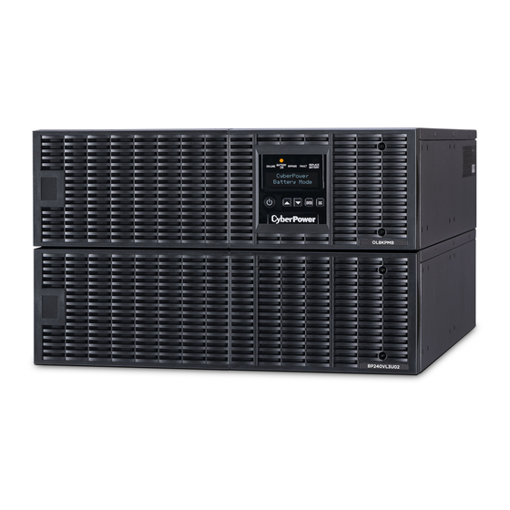
OVERVIEW POWER MODULE OL6KPMB/OL8KPMB/ OL10KPMB Power Button / Power on Indicator Master ON/OFF for the UPS. Indicates that the UPS is on and supplying power. UPS Status / Fault / Replace Battery LED Indicator Indicates the status of the UPS whether is operating in Line, Battery or Bypass Mode, or the UPS has an internal fault or the battery needs to be replaced. -
Page 11: Maintenance Bypass Module
Input / Output Connectors Use these connectors to attach the Maintenance Bypass Module to the power module. MAINTENANCE BYPASS MODULE OL6KMBM OL8K10KMBM OL6KMBMHW OL8K10KMBMHW ©2018 Cyber Power Systems (USA), Inc. All rights reserved. All other trademarks are the property of their respective owners. -
Page 11: Maintenance Bypass Module
OVERVIEW CONT. POWER MODULE CONT. EPO (Emergency Power O ) Connector Enables an emergency UPS power-o from a remote location. Extended Battery Module Connector Connection for additional CyberPower Extended Battery Modules (EBM). Input / Output Connectors Use these connectors to attach the Maintenance Bypass Module to the power module. MAINTENANCE BYPASS MODULE OL6KMBM OL8K10KMBM... - Page 12 “CRITICAL” outlets, while stopping the power supply to equipment connected to “NONCRITICAL” outlets after a designated period of time. ©2018 Cyber Power Systems (USA), Inc. All rights reserved. All other trademarks are the property of their respective owners.
- Page 12 OVERVIEW CONT. Input Circuit Breaker Provides input overload and fault protection. Manual Bypass Switch Provides UPS output to connected equipment when turned to Normal. Provides utility power to connected equipment when turned to Bypass. Input / Output Terminal Block Connect to utility power/equipment load. Interlock Bracket Safety bracket to prevent accidental operation of maintenance bypass switch.
-
Page 13: Installing Your Ups System
6. This UPS is equipped with an auto-charge feature. When the UPS is connected to AC electrical service the battery will automatically charge, even when the unit is switched off. ©2018 Cyber Power Systems (USA), Inc. All rights reserved. All other trademarks are the property of their respective owners. -
Page 13: Installing Your Ups System
INSTALLING YOUR UPS SYSTEM SYSTEM BLOCK DIAGRAM Maintenance Bypass Internal Bypass Input Inverter Output Bypass Input Output Filter AC/DC DC/AC Filter Switch LCD Module Charger Control Battery AC/DC & USB & DB9 Monitoring SNMP Slot Line Mode Battery Mode Bypass Mode Maintenance Bypass HARDWARE INSTALLATION GUIDE Battery charge loss may occur during shipping and storage. - Page 14 When the over temperature occurs, please check the Troubleshooting section. If the condition persists, please contact CyberPower for technical support. ©2018 Cyber Power Systems (USA), Inc. All rights reserved. All other trademarks are the property of their respective owners.
- Page 14 INSTALLING YOUR UPS SYSTEM CONT. HARDWARE INSTALLATION GUIDE CONT. 7. To maintain an optimal battery charge, leave the UPS connected to AC electrical service at all times. 8. Before storing the UPS for an extended period of time, turn the unit OFF. Then cover it and store it with the batteries fully charged.
-
Page 15: Hardware Installation
M5X6L*4pcs and plastic washers *4pcs at the front of the rack. (Located in position 4 & position 8) Secure the rails to the rear of the rack using pan head screws M5X6L*4pcs and plastic washers *4pcs. ©2018 Cyber Power Systems (USA), Inc. All rights reserved. All other trademarks are the property of their respective owners. -
Page 15: Hardware Installation
HARDWARE INSTALLATION These versatile UPS systems can be mounted in a rackmount or vertical /tower orientation. This versatility is especially important to growing organizations with changing needs that value having the option to position a UPS on the floor or in the rackmount system. Please follow the instructions below for the respective mounting methods. - Page 16 The UPS will be secured by a safety locking mechanism midway of pulling it out of the rack. Use both hands to hold the UPS and press the safety locking tab to pull the UPS out. ©2018 Cyber Power Systems (USA), Inc. All rights reserved. All other trademarks are the property of their respective owners.
- Page 16 HARDWARE INSTALLATION CONT. RACKMOUNT INSTALLATION: RACKMOUNT EARS INSTALLATION CONT. Rackmount ear Rackmount rail Step 5: Place and secure the UPS on the rails Slide the hanging brackets on the UPS on to the rails mounted in the rack with the front of the unit facing toward you.
-
Page 17: Vertical/Tower Installation
Unscrew the upper panel of the UPS. Separate the upper panel from the UPS. Gently lift the LCD control panel out. Rotate it to the tower orientation. Reinstall it for a tower configuration. ©2018 Cyber Power Systems (USA), Inc. All rights reserved. All other trademarks are the property of their respective owners. -
Page 17: Vertical/Tower Installation
HARDWARE INSTALLATION CONT. VERTICAL/TOWER INSTALLATION Step 1: Adhere rubber pads Adhere the protective rubber pads on the bottom side of power module and extended battery module. Step 2: Attach the base stands and attach the dust covers Secure the tie bracket on top of the power module and extended battery module with the flat head screws (M5X7*4pcs). -
Page 18: Maintenance Bypass Module Installation
Maintenance Bypass Module to the Power module with four screws. OL6KPMB OL6KPMB OL8KPMB OL8KPMB OL10KPMB OL6KMBM OL10KPMB OL6KMBMHW OL8K10KMBM OL8K10KMBMHW OL6KPMB OL6KPMB OL8KPMB OL8KPMB OL10KPMB OL10KPMB OL6KMBM OL6KMBMHW OL8K10KMBM OL8K10KMBMHW ©2018 Cyber Power Systems (USA), Inc. All rights reserved. All other trademarks are the property of their respective owners. -
Page 18: Maintenance Bypass Module Installation
MAINTENANCE BYPASS MODULE INSTALLATION Step 1: Remove the cover from the Maintenance Bypass Module Loosen the two screws and remove the cover from the Maintenance Bypass Module to expose the connectors. OL6KMBMHW OL8K10KMBMHW OL6KMBM OL8K10KMBM Step 2: Attach the Maintenance Bypass Module to the Power Module Align the connectors of the Maintenance Bypass Module with the connectors of the Power module to attach the device and tighten the two screws to fix the cover on the Maintenance Bypass Module. -
Page 19: Electrical Installation
Loosen the four screws to remove the inspection window cover. Step 2: Remove the terminal block cover Loosen the four screws to remove the terminal block cover. ©2018 Cyber Power Systems (USA), Inc. All rights reserved. All other trademarks are the property of their respective owners. -
Page 19: Electrical Installation
MAINTENANCE BYPASS MODULE INSTALLATION CONT. ELECTRICAL INSTALLATION Check branch circuit breaker rating and wiring dimensions with the following table. BRANCH CIRCUIT UPS CAPACITY WIRING AWG WIRING mm BREAKER 6KVA 10 AWG 5.5 mm 8KVA 8 AWG 8.0 mm 10KVA 6 AWG 14.0 mm INPUT/OUTPUT CONFIGURATION Hardwire the input/output terminals as shown in the following diagram. -
Page 20: Input/Output Configuration
(Magnetic Contactor) will open. 2. Save your data and perform a controlled shutdown. 3. Contact CyberPower for repair. ©2018 Cyber Power Systems (USA), Inc. All rights reserved. All other trademarks are the property of their respective owners. -
Page 20: Input/Output Configuration
MAINTENANCE BYPASS MODULE INSTALLATION CONT. INPUT/OUTPUT CONFIGURATION CONT. Step 3: Input configuration Insert the input cable through the appropriate cable gland (not included) and connect the three wires to the input terminal block. Step 4: Output configuration Insert the output cable through the appropriate cable gland (not included) and connect the three wires to the output terminal block. -
Page 21: Without Backfeed Protection Configuration
4. The external isolation device must be installed in the Mains path. Mains L1 L2 PE IP-L1 IP-L2 PSDR 2A Fuse Backfeed (Slow Blow) AC-L1 AC-L2 ©2018 Cyber Power Systems (USA), Inc. All rights reserved. All other trademarks are the property of their respective owners. -
Page 21: Without Backfeed Protection Configuration
MAINTENANCE BYPASS MODULE INSTALLATION CONT. WITHOUT BACKFEED PROTECTION CONFIGURATION Hardwire the input terminals as shown in the following diagram. 2. Do not remove the interconnection wires (Jumper1 / Jumper2) on “Backfeed Protection Connector”. Mains L1 L2 PE IP-L1 IP-L2 PSDR Backfeed Jumper1 AC-L1... -
Page 22: Extended Battery Module Install
©2018 Cyber Power Systems (USA), Inc. All rights reserved. All other trademarks are the property of their respective owners. -
Page 22: Extended Battery Module Install
EXTENDED BATTERY MODULE INSTALLATION REAR PANEL DESCRIPTION BP240VL3U01 / BP240VL3U02 On-board Replaceable Fuse Cover Replaceable fuse is accessible from the rear panel. Service to be performed by qualified personnel only. AC Circuit Breaker Provides overload and fault protection. AC Output Outlet (IEC320 C13) Use this outlet to connect to the AC Input Inlet of a downstream Battery module. - Page 23 ©2018 Cyber Power Systems (USA), Inc. All rights reserved. All other trademarks are the property of their respective owners.
- Page 23 EXTENDED BATTERY MODULE INSTALLATION CONT. CONNECTION WITH POWER MODULE CONT. Step 1: Turn o the DC breaker on the EBM. Step 2: Loosen the two screws to remove the battery cable retention bracket of the power module. Step 3: Use the output cable of the EBM to connect the EBM to the Power module. Step 4: Rotate the battery cable retention bracket and tighten the two screws to fix battery cable.
- Page 24 Save the setting. This operation can also be done if there is an RMCARD installed in the UPS, or via PowerPanel® Business Edition Agent. Please see their respective User’s Manuals for instructions. ©2018 Cyber Power Systems (USA), Inc. All rights reserved. All other trademarks are the property of their respective owners.
- Page 24 EXTENDED BATTERY MODULE INSTALLATION CONT. CONNECTION WITH POWER MODULE CONT. Step 1: Connect the 1st EBM to the Power module following the instructions above. Step 2: Turn o the DC breaker of the 2nd EBM. Step 3: Loosen the two screws to remove the battery cable retention bracket of the 1st EBM. Step 4: Use the output cable of the 2nd EBM to connect the 2nd EBM to the 1st EBM.
-
Page 25: Optional Lcd Control Panel Installation
Connect a DB26 cable (not included) from LCD module to the “Remote Control Port” on the front panel as shown in the following figure. Step 4: Mount LCD Module on the Wall Wall mounting hole 5*13.8L ©2018 Cyber Power Systems (USA), Inc. All rights reserved. All other trademarks are the property of their respective owners. -
Page 25: Optional Lcd Control Panel Installation
OPTIONAL LCD CONTROL PANEL INSTALLATION Caution: Important Instructions It must be done by qualified personnel. To avoid electric shock, turn o and unplug the unit before proceeding with REMOTE CONTROL or WALL-MOUNTING INSTRUCTIONS. REMOTE CONTROL Step 1: Remove the Multifunction LCD Control Panel Unscrew the right panel of the power module. -
Page 26: Ups System Startup
8. Verify that the green “ON-LINE” LED illuminates solid, indicating that the UPS is operating in Line Mode and powering the output. ©2018 Cyber Power Systems (USA), Inc. All rights reserved. All other trademarks are the property of their respective owners. -
Page 26: Ups System Startup
UPS SYSTEM STARTUP After completing the hardware installation of the UPS, you are now ready to connect the UPS and connect your equipment. To start the UPS: Verify that the UPS input cable or terminal blocks are connected to AC source. 2. -
Page 27: Using The Ups System
Press this button to scroll down in the LCD menu. ENTER Press this button to select an option. Press this button to cancel or return to previous LCD menu. ©2018 Cyber Power Systems (USA), Inc. All rights reserved. All other trademarks are the property of their respective owners. -
Page 27: Using The Ups System
USING THE UPS SYSTEM LCD CONTROL PANEL LED INDICATORS - UPS STATUS ITEM LED INDICATORS COLOR UPS STATUS DESCRIPTION ON/OFF White UPS power is on. ON-LINE Green UPS is operating in Line Mode. BATTERY ON Yellow UPS is operating in Battery Mode. UPS is operating in Bypass Mode, Manual Bypass BYPASS Yellow... -
Page 28: Lcd Menu Tree
Clear Event Log Gateway Button OFF LOCK Charger Function Signal Inputs Charger Check With Transformer Backfeed Check Rest ReplaceBAT IP Address Reset LoadEnergy ©2018 Cyber Power Systems (USA), Inc. All rights reserved. All other trademarks are the property of their respective owners. -
Page 28: Lcd Menu Tree
Signal Inputs Charger Check With Transformer Backfeed Check Rest ReplaceBAT IP Address Reset LoadEnergy LowBat Capacity LowBat Runtime Period Battery Test ©2020 Cyber Power Systems (USA), Inc. All rights reserved. All other trademarks are the property of their respective owners. - Page 29 = XXK VA Displays the UPS Rating MCU Ver XXXX Displays the MCU Firmware Version Model Name Displays the UPS Model Name ©2018 Cyber Power Systems (USA), Inc. All rights reserved. All other trademarks are the property of their respective owners.
- Page 29 USING THE UPS SYSTEM CONT. LCD Control Panel Main Menu Press “ENTER” button to enter the “Main Menu”. MAIN MENU DESCRIPTION Information Displays the UPS information. Configure Displays the UPS settings that can be configured by the user. Displays the 5 most recent events, by event count, time (day/hour/minute), and Event Log event description.
- Page 30 The Battery has been discharged to low level. Load Over Set% The UPS has detected Output Watt or VA has exceeded user set parameter. ©2018 Cyber Power Systems (USA), Inc. All rights reserved. All other trademarks are the property of their respective owners.
- Page 30 USING THE UPS SYSTEM CONT. LCD Information Readout Cont. INFORMATION DATA DESCRIPTION MENU ITEMS DISPLAYED Date & Time - - - - / - - / - - - -:- - Displays the present Date & Time Next BATT XXX / XXXX Displays the next Battery Change Date &...
- Page 31 6. The first configuration parameter will be displayed on the second column of LCD screen. 7. Press the “p” and “q” buttons to scroll through the different parameters. ©2018 Cyber Power Systems (USA), Inc. All rights reserved. All other trademarks are the property of their respective owners.
- Page 31 6. The first configuration parameter will be displayed on the second column of LCD screen. 7. Press the “ ” and “ ©2020 Cyber Power Systems (USA), Inc. All rights reserved. All other trademarks are the property of their respective owners.
- Page 32 (2) Bypass frequency is inside the range of "Sync Freq Range". The setting [No Bypass] means the UPS is forbidden to transfer to Bypass when UPS has fault. ©2018 Cyber Power Systems (USA), Inc. All rights reserved. All other trademarks are the property of their respective owners.
- Page 32 USING THE UPS SYSTEM CONT. LCD Setting Configuration Cont. 8. Press the “ENTER” button to select the parameter you want to change. 9. You may be prompted to save the selection, if so press the “ENTER” button to save the setting. Some options are saved and started automatically.
- Page 33 NCL Control Outlet On Off] directly. When the user sets NCL [Outlet Off] , the NCL output power will turn off directly. ©2018 Cyber Power Systems (USA), Inc. All rights reserved. All other trademarks are the property of their respective owners.
- Page 33 USING THE UPS SYSTEM CONT. LCD Setting Configuration Cont. CONFIGURE AVAILABLE SETTINGS DEFAULT SETTING SUBMENU [Disable] [Enable] Disable [V Range= +/-15%] [V Range= +/-10%] (for [Enable]) When ECO mode is enabled the UPS will check the following specifications of Bypass quality ECO Mode V Range= +/-10% (1) Bypass voltage is inside the [V Range= +/-10%]...
- Page 34 USING THE UPS SYSTEM CONT. LCD Setting Configuration Cont. CONFIGURE AVAILABLE SETTINGS DEFAULT SETTING SUBMENU [English] [Español-Spanish] [Français-French] [Deutsch-German] Language English User can select the desired LCD control panel language. [Disable] [Enable] When the UPS input power source is a generator set Generator Mode Disable the UPS will operate normally without transferring to...
- Page 34 Sets [SBM] to activate the Smart Battery Management Charger Function to charge the batteries. Sets [Constant] to use trickle charge method to charge the batteries. ©2018 Cyber Power Systems (USA), Inc. All rights reserved. All other trademarks are the property of their respective owners.
-
Page 35: Manual Battery Test
Manual Battery Test Select “Activate” in the “Battery Test” option of the LCD screen and the unit will perform a manual battery test. ©2020 Cyber Power Systems (USA), Inc. All rights reserved. All other trademarks are the property of their respective owners. -
Page 35: Manual Battery Test
Manual Battery Test Select “Activate” in the “Battery Test” option of the LCD screen and the unit will perform a manual battery test. ©2018 Cyber Power Systems (USA), Inc. All rights reserved. All other trademarks are the property of their respective owners. - Page 36 USING THE UPS SYSTEM CONT. Graphic load/battery capacity display Press the “ESC” button to return to UPS Status. 2. Press the “ ” and “ ” buttons to scroll to “LOAD” and “BAT” Capacity. 3. Press the“ ” and “ ” buttons to scroll to “Charging” or “Discharging” Capacity. LOAD and BAT Capacity The LCD screen displays the Load and Battery capacity with a graphical icon.
- Page 36 Line Mode. Discharging Capacity The LCD screen displays the remaining battery capacity with a graphical icon while on Battery Mode. ©2018 Cyber Power Systems (USA), Inc. All rights reserved. All other trademarks are the property of their respective owners.
-
Page 37: Maintenance
Safety Precautions Warning: High voltage – Risk of Electric Shock Only use replacement batteries which are certified by Cyber Power Systems. Use of incorrect battery type is an electrical hazard that could lead to explosion, fire, electric shock, or short circuit. -
Page 37: Maintenance
CyberPower Systems encourages environmentally sound methods for disposal and recycling of its UPS products. Please dispose and/or recycle your UPS and batteries in accordance with local regulations. ©2018 Cyber Power Systems (USA), Inc. All rights reserved. All other trademarks are the property of their respective owners. - Page 38 MAINTENANCE CONT. BATTERY REPLACEMENT Step 1: Remove the front panels. Step 2: Remove the retaining screws from the battery retention cover and then remove the cover itself. Step 3: Pull the battery trays out slowly and then put the new battery trays into the compartment. Step 4: Insert the battery connectors and tighten the screws of battery retention cover.
- Page 38 Do not slide the Interlock Bracket when the LCD screen shows “Generator On” or “Converter On”. Do not turn the Manual Bypass Switch when hearing a warning beep from the Power Module. ©2018 Cyber Power Systems (USA), Inc. All rights reserved. All other trademarks are the property of their respective owners.
-
Page 39: Technical Specifications
MAINTENANCE CONT. Remove Maintenance Bypass Module Step 1: Slide the Interlock Bracket to the left Remove the yellow head screw that secures the Interlock Bracket. Slide the Interlock Bracket to the left. Step 2: Check the Power module auto transfer to Manual Bypass After Sliding the Interlock Bracket to the left, the Power Module will auto transfer to Manual Bypass. -
Page 39: Technical Specifications
Tighten the two screws and fix the cover on the Maintenance Bypass Module to hide the connectors. The Power Module has now been safely shutdown and you can perform routine maintenance or replacement. ©2018 Cyber Power Systems (USA), Inc. All rights reserved. All other trademarks are the property of their respective owners. - Page 40 MAINTENANCE CONT. Reattach Maintenance Bypass Module Step 1: Remove the cover from the Maintenance Bypass Module Loosen the two screws and remove the cover from the Maintenance Bypass Module to expose the connectors. Step 2: Reattach the Maintenance Bypass Module to the Power Module Reattach the Maintenance Bypass Module to the Power Module and tighten the two screws to fix the cover on the Maintenance Bypass Module.
- Page 40 After Sliding the Interlock Bracket to the right, the Power Module will auto transfer to Line Mode. Check the LCD screen shows “Line Mode”. ©2018 Cyber Power Systems (USA), Inc. All rights reserved. All other trademarks are the property of their respective owners.
- Page 41 TECHNICAL SPECIFICATIONS OL6KRTMB OL8KRTMB OL10KRTMB MODELS OL6KRTHW OL8KRTHW OL10KRTHW CONFIGURATION Capacity (VA) 6000 VA 8000 VA 10000 VA Capacity (Watts) 6000 W 8000 W 10000 W Form Factor Rackmount/Tower Energy-saving ECO Mode E ciency> 96% ECO Mode E ciency> 97%...
- Page 41 UPS Output Cut off Immediately or Input Fuse / Circuit Breaker Protection BATTERY Specifications (20) 12 V/7 Ah (20) 12 V/9 Ah Recharge Time 0-90% 4 hours 5 hours (Typical) ©2018 Cyber Power Systems (USA), Inc. All rights reserved. All other trademarks are the property of their respective owners.
- Page 42 Module Net Weight: 13/4.9 lb (5.9/2.2 kg) MBM/MBMHW SAFETY Conformance Approvals CE, UL1778, FCC part 15 Class A RoHS RoHS Compliant ©2020 Cyber Power Systems (USA), Inc. All rights reserved. All other trademarks are the property of their respective owners.
- Page 42 Module Net Weight: 13/4.9 lb (5.9/2.2 kg) MBM/MBMHW SAFETY Conformance Approvals CE, UL1778, FCC part 15 Class A RoHS RoHS Compliant ©2018 Cyber Power Systems (USA), Inc. All rights reserved. All other trademarks are the property of their respective owners.
- Page 43 TECHNICAL SPECIFICATIONS CONT. MODELS BP240VL3U01 BP240VL3U02 CONFIGURATION AC Input Voltage 180~280 V DC Output Voltage 240 Vdc DC Output Current 30 A 50 A PHYSICAL Dimensions L x W x H = 26 x 17 x 5.2in. (660 x 433 x 132 mm) Net Weight 167.2 lbs (76 Kg) 171.6 lbs (78 Kg)
- Page 43 32°F to 104°F ( 0°C to 40°C) Operating Relative 0 to 90% Non-Condensing Humidity SAFETY Conformance Approvals CE, UL1778, FCC part 15 Class A RoHS RoHS Compliant ©2018 Cyber Power Systems (USA), Inc. All rights reserved. All other trademarks are the property of their respective owners.
-
Page 44: Troubleshooting
TROUBLESHOOTING PROBLEM POSSIBLE CAUSE SOLUTION WARNING Your equipment requires more power than the UPS can provide. If the UPS Shut o non-essential equipment. If O/P Overload is in Line Mode then it will transfer to this solves the overload problem, the Bypass Mode;... -
Page 44: Troubleshooting
200-240 V electrical Disable Wiring Fault alarm on LCD service is provisioned with No ground wire. panel. a Neutral line. ©2018 Cyber Power Systems (USA), Inc. All rights reserved. All other trademarks are the property of their respective owners. - Page 45 TROUBLESHOOTING CONT. PROBLEM POSSIBLE CAUSE SOLUTION WARNING Utility power is out of range for the Check whether voltage or frequency Line Abnormal UPS to auto-restart. of utility power is out of range. Your attached equipment may have Output Short Output short circuit. problems, please remove them and check again.
- Page 45 Connected Equipment Guarantee. (Registration is not required for coverage, but note: if you do not register your purchase, you will be required to provide proof of purchase.) ©2018 Cyber Power Systems (USA), Inc. All rights reserved. All other trademarks are the property of their respective owners.
-
Page 46: Limited Warranty And Connected Equipment Guarantee
LIMITED WARRANTY AND CONNECTED EQUIPMENT GUARANTEE Read the following terms and conditions carefully before using the CyberPower OL6KRTMB/OL8KRTMB/ OL10KRTMB/OL6KRTHW/OL8KRTHW/OL10KRTHW. By using the Product you consent to be bound by and become a party to the terms and conditions of this Limited Warranty and Connected Equipment Guarantee (together referred to as this “Warranty”). -
Page 46: Limited Warranty And Connected Equipment Guarantee
2. Email us at tech@cpsww.com or Call us at (877) 297-6937. 3. If your product requires warranty service you must provide a copy of your dated purchase receipt or invoice. ©2018 Cyber Power Systems (USA), Inc. All rights reserved. All other trademarks are the property of their respective owners. - Page 47 How Do You Open A Connected Equipment Claim? Call us at (877) 297-6937 or write to us at Cyber Power Systems (USA), Inc., 4241 12th Ave. E., STE 400, Shakopee, MN 55379, or send us an e-mail message to claims@cpsww.com for instructions, within 10 days of the occurrence.
- Page 47 How Do You Open A Connected Equipment Claim? Call us at (877) 297-6937 or write to us at Cyber Power Systems (USA), Inc., 4241 12th Ave. E., STE 400, Shakopee, MN 55379, or send us an e-mail message to claims@cpsww.com for instructions, within 10 days of the occurrence.
- Page 48 LIMITED WARRANTY AND CONNECTED EQUIPMENT GUARANTEE CONT. What Are Some Examples Of What This Warranty Does Not Cover? This Warranty does not cover any software that was damaged or needs to be replaced due to the failure of the Product or any data that is lost as a result of the failure or the restoration of data or records, or the reinstallation of software.
- Page 48 4. Damages from fire, flood, wind, rain, rising water, leakage or breakage of plumbing, abuse, misuse or alteration of either the product or the Connected Equipment. ©2018 Cyber Power Systems (USA), Inc. All rights reserved. All other trademarks are the property of their respective owners.
- Page 49 The application of the United Nations Convention of Contracts for the International Sale of Goods is expressly excluded. CyberPower is the warrantor under this Limited Warranty. For further information please feel free to contact CyberPower at Cyber Power Systems (USA), Inc. | 4241 12th Ave E., STE 400, Shakopee, MN 55379 (877) 297-6937 | claims@cpsww.com...
- Page 49 For further information please feel free to contact CyberPower at Cyber Power Systems (USA), Inc. | 4241 12th Ave E., STE 400, Shakopee, MN 55379 (877) 297-6937 | claims@cpsww.com ©2018 Cyber Power Systems (USA), Inc. All rights reserved. All other trademarks are the property of their respective owners.
-
Page 50: Conformance Approval
CONFORMANCE APPROVAL FCC NOTICE This device complies with part 15 of the FCC Rules. Operation is subject to the following two conditions: (1) This device may not cause harmful interference, and (2) this device must accept any interference that may cause undesired operation. WARNING!! This equipment has been tested and found to comply with the limits for a Class A digital device, pursuant to part 15 of the FCC Rules. -
Page 50: Conformance Approval
Address: 4241 12th Avenue E, Suite 400 Shakopee, MN 55379, USA Hours of Operation: Monday – Friday, 7:00am – 6:00pm (CST) ©2018 Cyber Power Systems (USA), Inc. All rights reserved. All other trademarks are the property of their respective owners. - Page 51 For USA and Canada | 4241 12th Ave East, Suite 400, Shakopee, MN 55379 | Toll-free: 877.297.6937 For all other regions | Please visit our website for local contact information. Copyright © 20 Cyber Power Systems, Inc. All rights reserve.
- Page 51 For USA and Canada | 4241 12th Ave East, Suite 400, Shakopee, MN 55379 | Toll-free: 877.297.6937 For all other regions | Please visit our website for local contact information. Copyright © 2017 Cyber Power Systems, Inc. All rights reserve.
Need help?
Do you have a question about the OL6KRTMB and is the answer not in the manual?
Questions and answers