
Subscribe to Our Youtube Channel
Related Manuals for Cyber Power OLS6000ERT6U


Summary of Contents for Cyber Power OLS6000ERT6U
- Page 1 Userˊs Manual OLS6000ERT6U OLS10000ERT6U OLS6000ERT6UM OLS10000ERT6UM CyberPower Systems Inc. www.cyberpower.com K01-C000250-02...
-
Page 2: Table Of Contents
CONTENT: Safety ......................1 1.1. Installation ....................1 1.2. Operation ....................1 1.3. Maintenance, Servicing and Faults .............2 1.4. Transport ....................3 1.5. Storage .......................3 1.6. Standards ....................3 Description of Commonly Used Symbols ............4 Introduction ....................4 3.1. Feature .......................5 3.2. Electrical Specifications ................6 3.3. Operating Environment ................7 3.4. - Page 3 Battery Maintenance .................. 38 11. Communication Port ..................39 11.1. USB Interface ..................39 11.2. RS232 Interface ..................39 11.3. Intelligent slot ..................39...
-
Page 4: Safety
1. Safety Please read carefully the following user manual and the safety instructions before installing the unit or using the unit! 1.1. Installation This is permanently connected equipment, and it must be installed by qualified maintenance personnel. Condensation may occur if the UPS is moved directly from a cold to a warm environment. -
Page 5: Maintenance, Servicing And Faults
not connected to the building wiring terminal, for there is internal current source (batteries). In order to fully disconnect the UPS, first turn the input breaker in the "OFF" position, then disconnect the mains lead. Indiscriminate operation of switches may cause output loss or damage to equipment. -
Page 6: Transport
1.4. Transport Please transport the UPS only in the original packaging to protect against shock and impact. 1.5. Storage The UPS must be stockpiled in the room where is ventilated and dry. 1.6. Standards * Safety IEC/EN 62040-1 * EMI Conducted Emission........:IEC/EN 62040-2 Category C3 Radiated Emission........:IEC/EN 62040-2... -
Page 7: Description Of Commonly Used Symbols
DC voltage, the inverter generates an AC sinusoidal voltage, which constantly supplies the loads. In the event of power failure, the maintenance-free batteries power the inverter. This manual covers the UPS listed as follows. Mode NO. Type OLS6000ERT6U(M) Standard OLS6000ERT6U(M) -
Page 8: Feature
3.1. Feature This series UPS is a new generation of UPS, which provides the outstanding reliability, and most cost-performance ratio in the industrial. Following benefit the product has: True online double-conversion technology with high power density, frequency independence and generator compatibility. ... -
Page 9: Electrical Specifications
② Output Connector: Use this output connector to connect the Battery module and the Power module. ③ Battery Input Terminal Block: Use this input Terminal Block to daisy chain the next Battery module. 3.2. Electrical Specifications Model OLS6000ERT6U(M) OLS10000ERT6U(M) Input Phase Single Voltage Rage... -
Page 10: Operating Environment
<95% <1000m 0℃~40℃ -15℃~50℃ Note: The load capacity should be derated 1% every 100m heightened on the basis of 1000m. 3.4. Dimensions and Weights Dimensions Model Net Weight(kg) W×H×D(mm) OLS6000ERT6U 438*261*680 72.5 OLS10000ERT6U 438*261*680 OLS6000ERT6UM 438*261*821 75.1 OLS10000ERT6UM 438*261*821 88.6... -
Page 11: Unpacking
4. Unpacking Power Module Contains: Power Module Power Module User’s Manual RS232 Cable USB Communication Parallel Port Parallel Cable (optional) Cable Cover Plate Rackmount Ears Rackmount Left Rail Rackmount Right Rail Terminal*11PCS (Stands)*2PCS Flat Head Screws: Pan Head Screws: Screw Hole Dust Plastic Washers M4X8L*8PCS M5X12L*13PCS... - Page 12 Battery Module Contains: Battery Module Rackmount Ears Rackmount Left Rail Rackmount Right Rail (Stands)*2PCS Pan Head Screws: Screw Hole Dust Flat Head Screws: M5X12L*13PCS covers*8PCS M4X8L*8PCS Plastic Washers*8PCS Battery Cable(RED)
- Page 13 *The Below table only for OLS6000ERT6UM/OLS10000ERT6UM Manual Bypass PDU Contains: Manual Bypass PDU User’s Manual Bypass PDU Manual UPS Input Cable(BLUE) Terminal Flat Head Screws: UPS Output Cable(GRAY) M4X8L*8PC Round Head Screws: Rackmount Ears*2PCS M3X6L*4PC ***Manual Bypass PDU installed and used please refer to the User’s Manual of Manual Bypass PDU.
-
Page 14: Hardware Installation
5. Hardware Installation CAUTION! To prevent the risk of fire or electric shock, only use the supplied hardware to attach the mounting brackets. 5.1. Rackmount Installation UPS systems can be mounted in a rackmount or vertical tower orientation. This versatility is especially important to growing organizations with changing needs that value having the option to position a UPS on a floor or in a rackmount system. - Page 15 : Step2.Rackmount rails installation The rails adjust to mount in 48-cm (19-inch) panel racks from 52 to 91.5cm (20.5 to 36 inches) deep. Select the proper holes in the rack for positioning the Power module in the rack. The Power module takes up position 1 through position 9.
-
Page 16: Vertical/Tower Installation
: Step3.Install the Power module on the rack Place the Power module on a flat stable surface with the front of the unit facing toward you. Secure the Power module to your rack with four M5X12L screws at the front of the rack. (Located in position 2 & position 8). Once completed, perform the same steps for the Battery module. - Page 17 Unscrew the left panel of the Power module. Separate the left panel from Power module. Rotate the LCD module to the left. Reinstall it for a tower configuration . Last tighten the screws to fix the left panel and the right panel.
- Page 18 : Step2.Attach the base stands Tighten the screws (M5X12*4pcs) of the base stands (rackmount ears) onto the bottom of Power module and Battery module. Insert dust cover into the rackmount ear screw holes that are not being used.
-
Page 19: Electrical Installation
For safety, please cut off the mains power switch before installation! When installing the electrical wiring, please note the nominal amperage of your incoming feeder. : Use cable cross section and protective device specification Model OLS6000ERT6U(M) OLS10000ERT6U(M) 6mm² 10mm² Protective earthing conductor Min cross section... - Page 20 Open the terminal block cover located on the rear panel of Power module, please refer to the appearance diagram. For OLS6000ERT6U(M), it is recommended to select the UL1015 10AWG/6mm² or other insulated wire which complies with AWG Standard for the Power module input and output wirings.
-
Page 21: Important Notes
10) It is requested to use the accessorial terminal splices which can be compacted on the wires tightly, to ensure the connection between the wires and the terminal block is reliable. Parallel Mode Output L Input Ground Input N Parallel Mode Output N Output Ground Input L Single Mode Output L... -
Page 22: Operating Procedure For Connecting With The Battery Module
printer to the Power module, the start-up power should be used for calculating the capacity of the Power module, as its start-up power consumption is too big to make the Power module which capacity is small fail easily. 6.2. Operating Procedure for Connecting with the Battery module Loosen the screws to remove the Terminal Block Cover located on the rear panel of Power module. -
Page 23: Epo Connection
Connect the Battery Cable to the Battery module. Once completed, retighten the Block Cover. 6.3. EPO Connection EPO (Emergency power off): when the emergency occurs, such as the failure of load, the UPS can cut off the output at once by operating the EPO port manually. :... -
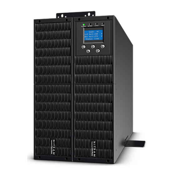
Page 24: Operation
7. Operation 7.1. Display Panel The UPS has a five-button, dot matrix LCD with white text and a blue background. Besides the LCD, the UPS has four colorized LED to provide more convenient information. Fig.7-1 LCD Panel : Control button functions The Button Function illustration... - Page 25 Press this button more than 200ms to move the focus to the up menu Press this button for more than 200ms to move the focus Down to the down menu LED definition: Normal BATTERY BYPASS FAULT UPS state (Green LED) (Yellow LED) (Yellow LED) (Red LED)
-
Page 26: Turning On And Turning Off Ups
The UPS provides useful information about UPS itself, load status, battery, events, identification, and settings through the front panel display. During powering on, the LCD would display the CyberPower logo for several seconds and then enter to the default page which shows the UPS status summary. On the UPS status screen it provides the following information: ... -
Page 27: Lcd Operation
powered on. At this time the fan begins to rotate, LCD will show "CyberPower". Then LCD will show the default UPS status summary screen after UPS finishing self-test. By pressing button continuously for more than 1s, the buzzer will beep for 1s, UPS starts to turn on. - Page 28 menu, event menu and identification menu. See Fig.7-3. Alarm 0002:12:20:00 Cyberpower Line site 2/10 Up>200mS Down>200mS Up>200mS Down>200mS Alarm Alarm Enter>200mS 0002:12:00:00 0002:12:00:00 Overload Overload Control ESC>200mS ESC>200mS 1/10 1/10 Setting Events ESC>200mS Fault Fault Enter>200mS 0003:12:00:00 0003:12:00:00 Over tempearture Over tempearture ESC>200mS Down>200mS...
- Page 29 Buzzer mute Clr EPO status Buzzer mute Clr EPO status Battery test Battery test Single UPS off Single UPS off Please input Password Sub setting... **** Event 0001:12:00:00 Utility abnormal 1/10 Alarm Control 0002:12:00:00 Setting Overload Events 1/10 Fault 0003:12:00:00 Over tempearture Clear all events Events&alarms...
- Page 30 : The control menu , enter the menu of "Control". The display would enter the next By pressing control menu screen. Buzzer mute Battery test: is one command to control all UPS in a parallel system to do the battery test at the same time. Clear EPO status: once EPO status is enabled, the UPS output would be cut off.
- Page 31 Short circuit clearance enabled/disabled disabled Power strategy** normal/ECO/converter normal Rated output voltage 208/220/230/240V 230V Output frequency 50/60Hz 50Hz Bypass voltage low range 10%,15%,20% Bypass voltage high range 10%,15% Bypass frequency range 1%~10% ECO voltage range 10%,15% ECO frequency range 1%~10% Standard/Customized Ext.
-
Page 32: Special Function
8. Special Function The series UPS has some special functions, which could satisfy some special application of user. And the functions have own features, please contact your local distributor for further information before using the function. 8.1. ECO Function : Brief introduction of ECO function If ECO function is set to enable, after the UPS is turned on, the power used by the load is directly supplied from the mains power via internal filter while the utility... -
Page 33: Parallel Function
power strategy setting menu by following chapter of 7.3. 8.3. Parallel Function : Brief introduction of the redundancy N+X is currently the most reliable power supply structure. N represents the minimum UPS number that the total load needs, X represents the redundant UPS number, i.e. - Page 34 Connect the output wires of each UPS to an output breaker panel, and connect each output breaker to a main output breaker and then to the loads. CAUTION: Each UPS needs an independent battery pack. Please refer to the wiring diagram in the following diagram. OUTPUT BATTERY INPUT...
- Page 35 TO UTILITY Main Maintenance Bypass Switch Main Input Breaker Main Output Breaker TO LOAD Fig.8-3 Parallel installation diagram The distance between the UPS in parallel and the breaker panel is required to be less than 20 meters. The difference between the wires of input and output of the UPS is required to be less than 20%.
- Page 36 than 0.5V. If the difference is more than 0.5V, the UPS need to be regulated. 10) Press the button of one UPS, each UPS would start to turn off and transfer to the Bypass mode, switch on the output breaker of each UPS to parallel all the output of UPS together.
-
Page 37: Trouble Shooting
install a new parallel system". Switch on the main input breaker and the main output breaker, and set the main maintenance bypass switch from "BPS" to "UPS", Press the button of one UPS, each UPS would start to turn on, after turning on, the UPS should work parallel in the Line mode. - Page 38 Battery voltage is Check if the battery quantity is Battery Over Voltage higher than normal right. value The UPS will turn off the Battery is over Over Charge charger until the battery voltage charged is normal The ambient Check the environment Amb NTC abnormal temperature is too ventilation.
-
Page 39: Trouble Shooting According To Fault Indication
9.2. Trouble Shooting According To Fault Indication Problem Displayed Possible cause Remedy Remove all the loads. Turn off the UPS. Check if UPS output and loads Output short Output short circuit is short circuit. Ensure short circuit is removed before turning on again. Check the loads and remove some Over load Over load... -
Page 40: Trouble Shooting In Else Cases
9.3. Trouble Shooting In Else Cases Problem Possible cause Remedy Check the building wiring and No indication, no warning tone even though system is connected No input voltage input cable. Check if the input to mains power supply breaker is closed BYPASS LED light up even though Inverter not Press button... -
Page 41: Battery Maintenance
Battery Maintenance Battery replacement should be performed by qualified personnel. This series UPS only requires minimal maintenance. The batteries used for battery pack are value regulated sealed lead-acid maintenance free battery. These models require minimal repairs. The only requirement is to charge the UPS regularly in order to maximize the expected life of the battery. -
Page 42: Communication Port
Communication Port 11.1. USB Interface The USB port is compliance with USB 1.1 protocol for its communication software. 11.2. RS232 Interface The RS-232 port is available for UPS monitoring, control, and firmware updates. 11.3. Intelligent slot This series is equipped with an intelligent slot for other optional card to achieve remote management of the UPS through internet / intranet.
Need help?
Do you have a question about the OLS6000ERT6U and is the answer not in the manual?
Questions and answers