Table of Contents
Advertisement
Quick Links
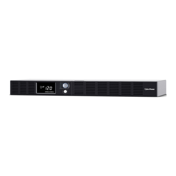
FEATURES
1.
LCD Module Display
2. Power On Indicator
3. Power Switch
4. LCD Function Selected Switch
5. Battery and Surge Protected Outlets
6. Full-Time Surge Protection Outlets
7. SNMP / HTTP Network Slot
4241 12th Avenue East, Suite 400 | Shakopee, MN 55379 | CyberPowerSystems.com
YOUR ULTIMATE ALLY IN POWER
INTELLIGENT UPS SERIES
OR500LCDRM1U / OR700LCDRM1U
USER MANUAL
Cyber Power Systems (USA), Inc.
8. Communication Protection Ports RJ45
9. USB Port to PC
10. Dry Contact
11. Circuit Breaker
12. AC Input
13. Electrical Wiring Fault Indicator (Red)
Advertisement
Table of Contents


Need help?
Do you have a question about the OR500LCDRM1U and is the answer not in the manual?
Questions and answers