
Related Manuals for Cyber Power HSTP3T10KE


Summary of Contents for Cyber Power HSTP3T10KE
- Page 1 User’s Manual HSTP3T10KE/ KEBC/ KEBCWOB HSTP3T15KE/ KEBC/ KEBCWOB HSTP3T20KE/ KEBC/ KEBCWOB HSTP3T30KE/ KEBC/ KEBCWOB HSTP3T40KE/ KEBC/ KEBCWOB Cyber Power Systems, Inc. www.cyberpower.com...
- Page 2 Ver 1.0.3...
-
Page 3: Safety Precautions
Safety Precautions Safety Precautions This manual contains information concerning the installation and operation of Tower UPS. Please carefully read this manual prior to installation. The Tower UPS cannot be put into operation until it is commissioned by engineers approved by the manufacturer (or its agent). Not doing so could result in personnel safety risk, equipment malfunction and invalidation of warranty. - Page 4 Safety Precautions Move & Install Keep the equipment away from heat source or air outlets. In case of fire, use dry powder extinguisher only, any liquid Danger extinguisher can result in electric shock. Do not start the system if any damage or abnormal parts founded.
-
Page 5: Battery Safety
Safety Precautions in this manual. Battery Safety All the battery maintenance and servicing procedures involving internal access need special tools or keys and should be carried out only by trained personnel. When connected together, the battery terminal voltage will exceed 400Vdc and is potentially lethal. - Page 6 Safety Precautions eyes and your skin may be damaged by the acid. At the end of battery life, the battery may have internal short circuit, drain of electrolytic and erosion of positive/negative plates. If this condition continues, the battery may have temperature out of control, swell or leak.
-
Page 7: Table Of Contents
Contents Contents Chapter 1 Product Introduction .................... 1 1.1 System Configuration .................... 1 1.2 Operation Mode ..................... 1 1.2.1 Normal Mode ...................... 1 1.2.2 Battery Mode ...................... 2 1.2.3 Bypass Mode ...................... 2 1.2.4 Maintenance Mode (Manual Bypass) ..............2 1.2.5 ECO Mode ...................... - Page 8 Contents 4.2.5 Switching the UPS into Normal Mode from Maintenance Bypass Mode ..37 4.3 Battery Maintenance ................... 37 4.4 EPO ........................38 4.5 Installation of Parallel Operation System ............39 4.5.1 Parallel system diagram ................... 39 4.5.2 Parallel system setting ..................41 Chapter 5 Maintenance .....................
-
Page 9: Chapter 1 Product Introduction
Chapter 1 Product Introduction Chapter 1 Product Introduction 1.1 System Configuration The Tower UPS is configured by the following part: Rectifier, Charger, Inverter, Static Switch and Manual Bypass Switch. One or several battery strings should be installed to provide backup energy once the utility fails. The UPS structure is shown in Fig. 1-1. Fig.1-1 UPS Configuration 1.2 Operation Mode The Tower UPS is an on-line, double-conversion UPS that permits operation in the... -
Page 10: Battery Mode
Chapter 1 Product Introduction 1.2.2 Battery Mode Upon failure of the AC mains input power, the inverter of power modules, which obtain power from the battery, supply the critical AC load. There is no interruption in power to the critical load upon failure. After restoration of the AC mains input power, the” Normal mode”... -
Page 11: Eco Mode
Chapter 1 Product Introduction Fig.1-5 Maintenance mode operation diagram Danger During Maintenance mode, dangerous voltages are present on the terminal of input, output and neutral, even with all the modules and the LCD turned off. 1.2.5 ECO Mode To improve system efficiency, UPS rack system works in Bypass mode at normal time, and inverter is standby. -
Page 12: Frequency Converter Mode
Chapter 1 Product Introduction 1.2.7 Frequency Converter Mode By setting the UPS to Frequency Converter mode, the UPS could present a stable output of fixed frequency (50 or 60Hz), and the bypass static switch is not available. 1.3 UPS Structure 1.3.1 UPS Configuration The UPS configuration is provided in Table 1.1 Table1.1 UPS Configuration... - Page 13 Chapter 1 Product Introduction Fig.1-8 20/30kVA System outlook (Long backup type) Fig.1-9 20/30kVA System outlook (Standard backup type) HSTP3T 10-40 KE/KEBC/KEBCWOB User Manual...
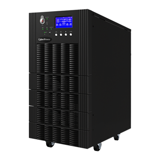
- Page 14 Chapter 1 Product Introduction Fig.1-10 10-40kVA front appearance Fig.1-11 10/15 kVA back appearance HSTP3T 10-40 KE/KEBC/KEBCWOB User Manual...
- Page 15 Chapter 1 Product Introduction Fig.1-12 20/30kVA back appearance 40kVA long type back appearance Fig.1-13 HSTP3T 10-40 KE/KEBC/KEBCWOB User Manual...
- Page 16 Chapter 1 Product Introduction 40kVA standard type front appearance Fig.1-13 Note The Standard product is configured with single input; the dual-input option is available, with an additional breaker for the main input HSTP3T 10-40 KE/KEBC/KEBCWOB User Manual...
-
Page 17: Chapter 2 Installation Instruction
Chapter 2 Installation Instruction Chapter 2 Installation Instruction 2.1 Location As each site has its requirements, the installation instructions in this section are to act as a guide for the general procedures and practices that should be observed by the installing engineer. - Page 18 Chapter 2 Installation Instruction Fig.2-1-1 Size of the 10/15 kVA UPS of Long Backup Type (Unit : mm) Fig.2-1-2 Size of the 10/15 kVA UPS of standard backup Type (Unit : mm) Fig.2-2-1 Size of the 20/30kVA UPS of Long Backup Type (Unit : mm) HSTP3T 10-40 KE/KEBC/KEBCWOB User Manual...
- Page 19 Chapter 2 Installation Instruction Fig.2-2-2 Size of the 20/30kVA UPS of Standard Backup Type (Unit : mm) Fig.2-3-1 Size of the 40kVA UPS Long Backup Type (Unit : mm) HSTP3T 10-40 KE/KEBC/KEBCWOB User Manual...
- Page 20 Chapter 2 Installation Instruction Fig.2-3-2 Size of the 40kVA UPS Standard Type (Unit: mm) Fig.2-4 Room reserved for the cabinet(Unit:mm) HSTP3T 10-40 KE/KEBC/KEBCWOB User Manual...
-
Page 21: Unloading And Unpacking
Chapter 2 Installation Instruction The weight for the UPS cabinet is shown in Table 2.1 Table 2.1Weight for the cabinet Configuration Weight 10kVA/15kVA Standard Backup Type 52kg(No Batteries Included) 10kVA/15kVA Long Backup Type 31kg 20kVA/30kVA Standard Backup Type 89kg(No Batteries Included) 20kVA/30kVA Long Backup Type 50kg 40kVA Standard Backup Type... - Page 22 Chapter 2 Installation Instruction 4. Remove the protective foam around the cabinet. Fig.2-7 Remove the protective foam 5. Check the UPS. (a) Visually examine if there are any damages to UPS during transportation. If any, contact to the carrier. (b) Check the UPS with the list of the goods. If any items are not included in the list, contact to our company or the local office.
-
Page 23: Positioning
Chapter 2 Installation Instruction 2.3 Positioning 2.3.1 Positioning Cabinet The UPS cabinet has two way of supporting itself: One is to support itself temporarily by the four wheels at the bottom, making it convenient to adjust the position of the cabinet;The other is by anchor bolts to support the cabinet permanently after adjusting the position of the cabinet. -
Page 24: Battery
Chapter 2 Installation Instruction 2.4 Battery Three terminals (positive, neutral, negative) are drawn from the battery unit and connected to UPS system. The neutral line is drawn from the middle of the batteries in series (See Fig.2-9). 40 batteries in series Fig.2-9 Battery string wiring diagram Danger The battery terminal voltage is of more than 200Vdc, please follow the safety instructions to... -
Page 25: Power Cables
Chapter 2 Installation Instruction 2.6 Power Cables 2.6.1 Specifications The UPS power cables are recommended in Table 2.2. Table 2.2 Recommended cables for power cables Contents 10/15kVA 20/30kVA 40kVA Main Input Current(A) 18/28A 35/55A Cable Section Main Input (mm²) Main Output Current(A) 15/23A 30/45A Cable... -
Page 26: Circuit Breaker
Chapter 2 Installation Instruction Cables crimped Output 4.9Nm OT terminal Cables crimped 4.9Nm OT terminal 2.6.3 Circuit Breaker The circuit breakers (CB) for the system are recommended in Table 2.4. Table 2.4 Recommended CB Installed position 10/15kVA 20kVA 30kVA 40kVA Battery CB 32A,250Vdc 50A,250Vdc... -
Page 27: Control And Communication Cables
Chapter 2 Installation Instruction Fig.2-13 Connections terminals for 40kVA 3. Connect the protective earth wire to protective earth terminal (PE). 4. Connect the AC input supply cables to the Input terminal and AC output supply cables to the Output terminal. 5. -
Page 28: Dry Contact Interface
Chapter 2 Installation Instruction Fig.2-14 Dry contact &communication interface 2.7.1 Dry Contact Interface Dry contact interface includes port J2-J11 and the functions of the dry contact are shown in Table 2.5. Table 2.5 Functions of the port Port Name Function J2-1 TEMP_BAT Detection of battery temperature... - Page 29 Chapter 2 Installation Instruction Output dry contact, (Normally closed) function is settable. J9-1 GENERAL_ALARM_NC Default: Fault alarming Output dry contact, (Normally open) function is settable. J9-2 GENERAL_ALARM_NO Default: Fault alarming J9-3 GENERAL_ALARM_GND Common terminal for J9-1 and J9-2 Output dry contact, (Normally closed) function is settable.
- Page 30 Chapter 2 Installation Instruction Remote EPO Input Port J4 is the input port for remote EPO. It requires shorting NC and +24V and disconnecting NO and +24V during normal operation, and the EPO is triggered when opening NC and +24V or shorting the NO and +24V.
- Page 31 Chapter 2 Installation Instruction BCB Input Port The default function of J6 and J7 are the ports of BCB. The port diagram is shown in Fig.2-18, and description is shown in Table 2.9. +24V +24V +24V Fig.2-18 BCB Port Table 2.9 Description of BCB port Port Name Function...
- Page 32 Chapter 2 Installation Instruction Port Name Function Battery warning relay (normally open) will be J8-2 BAT_LOW_ALARM_NO closed during warning J8-3 BAT_LOW_ALARM_GND Common terminal General Alarm Output Dry Contact Interface The default function of J9 is the general alarm output dry contact interface. When one or more warnings are triggered, an auxiliary dry contact signal will be active via the isolation of a relay.
-
Page 33: Communication Interface
Chapter 2 Installation Instruction Table 2.12 Utility failure warning dry contact interface description Port Name Function Mains failure warning relay(normally closed) will J10-1 UTILITY_FAIL_NC be open during warning Mains failure warning relay (normally open) will J10-2 UTILITY_FAIL_NO be closed during warning J10-3 UTILITY_FAIL_GND Common terminal... -
Page 34: Chapter 3 Lcd Panel
Chapter 3 LCD Panel Chapter 3 LCD Panel 3.1 Introduction This chapter introduces the functions and operator instructions of the operator control and display panel in detail, and provides LCD display information, including LCD display types, detailed menu information, prompt window information and UPS alarm information. 3.2 LCD panel for Cabinet The structure of operator control and display panel for cabinet is shown in Fig.3-1. -
Page 35: Control And Operation Keys
Chapter 3 LCD Panel Indicators State Description Battery and battery converter normal, battery not charging Steady Load supplied by bypass green Bypass abnormal or out of normal range, or static bypass Bypass Steady red indicator switch fault Flashing red Bypass voltage abnormal Bypass normal Steady Load supplied by inverter... -
Page 36: Lcd Screen
Chapter 3 LCD Panel 3.2.3 LCD Screen After the monitoring system starts self-test, the system enters the home page, following the welcome window. The home page is shown in Fig.3-2. Home page consists of System Information Window, Menu Window and Current Command and Record Menu. - Page 37 Chapter 3 LCD Panel Select the icon, system enters the corresponding page; take the icon (Main Input) for example, as shown in Fig.3-3. HOME I/P MAIN NEXT 220.1 V 220.1 V 220.1 V 45.0 A 45.0 A 45.0 A 50.01 Hz 50.01 Hz 50.01 Hz 0.99 PF...
-
Page 38: System Information Window
Chapter 3 LCD Panel 3.3 System Information Window System Information Window displays the current time and UPS model, as is shown in the following Table 3.5. Table 3.5 Description of System Information Window Content Description UPS mode:3-phase in 3-phase out 20kVA,standard HSTP3T20KE backup type 16:30... -
Page 39: Event List
Chapter 3 LCD Panel Menu Menu item Meaning name alarm on LCD History log Display all history logs. Display calibration Adjust the accuracy of LCD display MONTH-DATE-YEAR and YEAR-MONTH-DATE Date format set formats can be selected Date & Time Date/Time set Function Settings Language set... - Page 40 Chapter 3 LCD Panel capacity Less-Clear Incident above disappears Generator Input-Set Generator as the AC Input Source Generator Input-Clear Incident above disappears Utility Abnormal-Set Utility (Grid) Abnormal Utility Abnormal-Clear Incident above disappears Bypass Sequence Error-Set Bypass voltage Sequence is reverse Bypass Sequence Error-Clear Incident above disappears Bypass Volt Abnormal-Set...
- Page 41 Chapter 3 LCD Panel Incident above disappears INV Overload Tout-Clear Inverter Over Temperature Inverter Over Temp.-Set Incident above disappears Inverter Over Temp.-Clear Inhibit system transfer from bypass to UPS On UPS Inhibited-Set (inverter) On UPS Inhibited-Clear Incident above disappears Manual Transfer Byp-Set Transfer to bypass manually Manual Transfer Byp-Set Cancel to bypass manually...
- Page 42 Chapter 3 LCD Panel DC Bus Over Volt-Clear Incident above disappears REC Soft Start Fail-Set Rectifier soft start fails REC Soft Start Fail-Clear Incident above disappears Relay Connect Fail-Set Relay in open circuit Relay Connect Fail-Clear Incident above disappears Relay Short Circuit-Set Relay shorted Relay Short Circuit-Clear Incident above disappears...
-
Page 43: Chapter 4 Operations
Chapter 4 Operations Chapter 4 Operations 4.1 UPS Start-up The UPS must be started up by commissioning engineer after the completeness of installation. The steps below must be followed: 1. Ensure all the circuit breakers are open. 2. Close the output circuit breaker (CB) and then the input CB and the system starts initializing. -
Page 44: Procedure For Switching Between Operation Modes
Chapter 4 Operations 4.2 Procedure for Switching between Operation Modes 4.2.1 Switching the UPS into Battery Mode from Normal Mode The UPS transfers to Battery model immediately after input circuit breaker disconnects from the utility. 4.2.2 Switching the UPS into Bypass Mode from Normal Mode Manual Byp Follow the path by selecting the icon of and then select... -
Page 45: Switching The Ups Into Normal Mode From Maintenance Bypass Mode
Chapter 4 Operations Waring Once the cover on the maintenance bypass breaker is removed, the system will transfer to bypass mode automatically. Waring Before making this operation, confirm the messages on LCD display to be sure that bypass supply is regular and the inverter is synchronous with it, so as not to risk a short interruption in powering the load. -
Page 46: Epo
Chapter 4 Operations BACK FUNCTION ManualByp/Esc Batt. Test Fault Clear Maint Test Manual INV Stop Test Fig.4.3 Battery maintenance 4.4 EPO The EPO button located in the operator control and display panel (with cover to avoid disoperation, see Fig.4-5) is designed to switch off the UPS in emergency conditions (e.g., fire, flood, etc.).To achieve this, just press the EPO button, and the system will turn off the rectifier, inverter and stop powering the load immediately (including the inverter and bypass output), and the battery stops charging or discharging. -
Page 47: Installation Of Parallel Operation System
Chapter 4 Operations 4.5 Installation of Parallel Operation System 4.5.1 Parallel system diagram Up to four UPS could be paralleled,with a diagram as shown in Fig.4-6. Power Supply UPS1 UPS2 UPS3 UPS4 Output Power Supply Load Connected Fig. 4-6 Parallel diagram The parallel board is located at the back of the UPS cabinet, as is shown in Fig.4-7. - Page 48 Chapter 4 Operations Fig.4-7 Location of the Parallel board All the parallel cables are designed to be shielded and double insulated, and are connected between the UPS to form a loop as shown below in Fig. 4-8. Fig.4-8 Parallel connection HSTP3T 10-40 KE/KEBC/KEBCWOB User Manual...
-
Page 49: Parallel System Setting
Chapter 4 Operations 4.5.2 Parallel system setting Parallel system connection For field installation, please connect the cables according to Fig.4-6 and Fig.4-8. In order to assure that all units are equally utilized and to comply with relevant wiring rules, the following requirements apply: 1. - Page 50 Chapter 4 Operations Fig.4-11 Connectors on Parallel board (PS1409_TF1) Fig.4-12 Connectors on Control board (PS1203_CT1) HSTP3T 10-40 KE/KEBC/KEBCWOB User Manual...
- Page 51 Chapter 4 Operations 1. Parallel boards settings A. For single UPS, no need parallel board. When a parallel board is installed, connectors of J33 to J42 should be shorted by the jumpers. B. For 2 UPS in parallel, short the connectors of J33/J35/J37/J39/J41 by jumpers on each board, keep connectors of J34/J36/J38/J39/J42 open C.
-
Page 52: Chapter 5 Maintenance
Chapter 5 Maintenance Chapter 5 Maintenance This chapter introduces UPS maintenance, including the maintenance instructions of power module and monitoring bypass module and the replacement method of dust filter. 5.1 Precautions 1. Only certified engineers are authorized to maintain the UPS. 2. -
Page 53: Installation Of Internal Battery
Chapter 5 Maintenance Warning If a battery has leakage or is damaged, it must be replaced, stored in a container resistant to sulfuric acid and disposed of in accordance with local regulations. The waste lead-acid battery is a kind of hazardous waste and is one of the major contaminants controlled by government. - Page 54 Chapter 5 Maintenance 3.Connect the battery cable according to the series number 4.Recover the cover Fig.5-1 Installation of inner battery for10/15K standard UPS Fig.5-2 shows the installation of batteries for 20/30K standard UPS. There are 8 groups of batteries in series, with 5 cells for each group. The interconnection among groups is via cable with Anderson Socket.
- Page 55 Chapter 5 Maintenance Layer 1. The positive of the battery 1# is connected to battery breaker CB4-2, via the cable labeled L1, and the negative of battery 40# is connected to CB4-6, via the cable labeled L2, as shown in Fig.5-2-2. Fig.5-2-2 Cable connection of Lay 1 Layer 2.
- Page 56 Chapter 5 Maintenance Fig.5-2-4 Cable connection of Lay 3 Layer 4. The positive of the battery 16# is connected to the negative of battery 15#, via the cable labeled L4, and the negative of battery 25# is connected to the positive of battery 26#, via the cable labeled L4.
- Page 57 Chapter 5 Maintenance For 40kVA the battery bank has four layers. Each lay has four packages with 5 batteries contained in one package.Fig5-3 shows the connection of each layer. Fig. 5-3 battery connection of each layer HSTP3T 10-40 KE/KEBC/KEBCWOB User Manual...
- Page 58 Chapter 5 Maintenance After the connected as shown in Fig 5-3, connect the connectors as following as zoomed in Fig Terminal+: W01-1 and W01-2 Terminal N: W03-1, W03-2, W03-4, W03-4 Terminal-: W02-1 and W02-2 Fig. 5-4 Battery terminal connection After connect the terminal, recover the cover as shown in the following Fig. 5-5 Fig.
-
Page 59: Chapter 6 Product Specification
Chapter 6 Product Specification Chapter 6 Product Specification This chapter provides the specifications of the product, including environmental characteristics mechanical characteristics and electrical characteristics. 6.1 Applicable Standards The UPS has been designed to conform to the following European and international standards: Table 6.1 Compliance with European and International Standards Item... -
Page 60: Electrical Characteristics
Chapter 6 Product Specification Color BLACK,RAL 7021 Protection Level IP20 IEC(60529) Model Unit 20/30KE 20/30KEBC 20/30KEBCWOB Dimension 250*680*770 350*738*1335 350*738*1335 W×D×H Weight Color BLACK,RAL 7021 Protection Level IP20 IEC(60529) Model Unit 40KE 40KEBC 40KEBCWOB Dimension 250*836*770 500*840*1400 500*840*1400 W×D×H Weight Color BLACK,RAL 7021 Protection Level... -
Page 61: Electrical Characteristics (Intermediate Dc Link)
Chapter 6 Product Specification 6.4.2 Electrical Characteristics (Intermediate DC Link) Table 6.6 Battery Items Unit Parameters Rated:±240V Battery bus voltage Quantity of Nominal 40=[1 battery(12V)] ,240=[1 battery(2V)] lead-acid cells V/cell 2.25V/cell(selectable from 2.2V/cell~2.35V/cell) Float charge (VRLA) voltage Constant current and constant voltage charge mode Temperature mV/ ℃... -
Page 62: Electrical Characteristics (Bypass Mains Input)
Chapter 6 Product Specification 6.4.4 Electrical Characteristics (Bypass Mains Input) Table 6.8 Bypass Mains Input Item Unit Value 380/400/415 Rated AC (three-phase four-wire and sharing neutral with the voltage bypass) 125% Long term operation; 125%~130% for 10min; % Overload 130%~150% for 1min; 150%~400% for 1s;...
Need help?
Do you have a question about the HSTP3T10KE and is the answer not in the manual?
Questions and answers