Table of Contents
Advertisement
Quick Links
Table of Contents
Topic
End-to-End Applications
Note: Refer to assembly direction
# 939600192 for assembly of
base power infeed.
If you have a problem, question, or request, call
your local dealer, or Coalesse at 1.800.627.6770
Or visit our website: www.coalesse.com
©
2015 Coalesse
San Francisco, California U.S.A.
Printed in U.S.A.
Assembly and Modular Table Power System Installation Instructions
Page
2
3
4
5
5
5
5
6
7
8
Rectangular Tables
90 Corner Top
for Train
Tables
®
Modesty Panel
Page 1 of 8
939505524 Rev D
Advertisement
Table of Contents

Related Manuals for Coalesse Train series


Summary of Contents for Coalesse Train series
-
Page 1: Table Of Contents
# 939600192 for assembly of base power infeed. 90 Corner Top Modesty Panel If you have a problem, question, or request, call your local dealer, or Coalesse at 1.800.627.6770 Or visit our website: www.coalesse.com © 2015 Coalesse San Francisco, California U.S.A. -
Page 2: Attach Stretcher To Legs
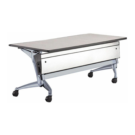
STRETCHER SHIPPED COMPONENTS: Attach Stretcher To Legs (1) Table top (2) Legs Unwrap the stretcher from package. (1) Stretcher HARDWARE: Attach the stretcher to each leg Stretcher Hardware: casting. (4) #730574 Allen Head Screws, 3/8-16 x 1” The Backer Plate (#811679) is BACKER PLATE (2) #811679 Stretcher Joint Backer Plate installed on the outside of the... -
Page 3: Attach Base To Table Top
Attach Base To Table Top Carefully place table top upside down onto carpet or other soft, clean surface. Lower base assembly into place onto the table top. The leg attachment brackets should fit into the pockets routed into the underside of the table top. Install (3) screws through each bracket at this time. -
Page 4: Attach Modesty Panel To Assembly
SHIPPED COMPONENTS (1) modesty panel MODESTY PANEL (1) hardware package HARDWARE PACKAGE (4) (73053705) torx head screws, 1/4-20 x 1/2” (1) (811772R) right-hand bracket, R (1) (811772L) left-hand bracket, L (1) latchlock tape on each bracket TOOLS REQUIRED (1) electric drill or rachet with T-27 torx bit Attach Modesty Panel To Assembly LATCHLOCK TAPE... -
Page 5: Modular Table Power System Installation
Modular Table Power System Installation WARNING 12" MAX. Risk of Fire or Electric Shock 1. For use in indoor, dry locations only. 2. Read and install in accordance with all assembly directions. 3. Only connect to products labeled "Modular Table Power System" by Steelcase. 4. -
Page 6: Modular Table Power Assemblies
Modular Table Power Assemblies Cable attachment hole Single Receptacle Double Receptacle locations for single receptacle cable. SHIPPED COMPONENTS: SHIPPED COMPONENTS: - 1 cable assembly - 1 cable assembly - 1 hardware kit - 1 hardware kit HARDWARE: HARDWARE: - 1 receptacle bracket - 2 receptacle brackets - 5 conduit clamps - 4 conduit clamps... -
Page 7: Installing Modular Cable For
Installing Modular Cable for End-to-End Applications (continued) Fasten receptacle bracket(s). CONDUIT CLAMP Fasten conduit snap-clips. RECEPTACLE Loosely fasten conduit clamps. Determine direction of power and orient male and female ends of cable assembly as required. Align ends flush with table edges and snap into clips. Note: Infeed has a female connector. -
Page 8: Cable Routing Restrictions
Cable Routing Restrictions In order for the flip-top mechanism to work properly, the mechanism area - handle, swing arm, top pivot and bumpers - must be free of any obstructions. When routing power cables, follow the recommended conduit path described on page 6, and avoid the shaded areas in the illustration shown on this page.
Need help?
Do you have a question about the Train series and is the answer not in the manual?
Questions and answers