Skipper DL850 Operation And Installation Manual
270 khz, 2 axis doppler navigational, sog plus stw speed log
Hide thumbs
Also See for DL850:
- Operation and installation manual (73 pages) ,
- Operation and installation manual (80 pages)
Table of Contents
Advertisement
Quick Links
Operation and Installation Manual
2 Axis Doppler Navigational
SKIPPER Electronics AS
Enebakkveien 150
P. O. Box 151, Manglerud
0612 Oslo, Norway
www.skipper.no
DL850 (270 kHz)
SOG + STW Speed Log
Telephone:
+47 23 30 22 70
Telefax:
+47 23 30 22 71
E-mail:
support@skipper.no
Co. reg. no:
NO-965378847-MVA
Document no: DM-D002-SC
Rev: 1650
For software ver: 4.04.01
Edition: 2017-09-25
Advertisement
Table of Contents

Related Manuals for Skipper DL850


Summary of Contents for Skipper DL850
- Page 1 DL850 (270 kHz) Operation and Installation Manual 2 Axis Doppler Navigational SOG + STW Speed Log SKIPPER Electronics AS Telephone: +47 23 30 22 70 Enebakkveien 150 Telefax: +47 23 30 22 71 Document no: DM-D002-SC P. O. Box 151, Manglerud E-mail: support@skipper.no...
- Page 2 SKIPPER Electronics AS Operation and Installation DL850 270 kHz Information: Please visit our web site www.skipper.no for additional information. Here you will find product bulletins, software updates, instruction manuals, installation procedures etc. Important • During installation, DO NOT CUT THE TRANSDUCER CABLE.
-
Page 3: Table Of Contents
Operation and Installation DL850 270 kHz SKIPPER Electronics AS Contents TERMINOLOGY ......................6 Units ..............................6 Abbreviations ............................6 1. INTRODUCTION ....................7 System Overview ..........................7 Sensor (Transducer) ..........................8 Transceiver unit ...........................8 Interfacing ............................9 Outputs ..................................9 Inputs .....................................9 Alarts .....................................9 Operator Unit ............................9 2. OPERATION .......................10 Screen Select ............................10... - Page 4 SKIPPER Electronics AS Operation and Installation DL850 270 kHz Transducer Maintenance ........................35 4. INSTALLATION ....................36 Handling warning ..........................36 Location..................................37 Operator Unit Installation ........................37 115/230 V selection on Combo Terminal board inside Display Unit................37 AC Voltage selection ..............................38 Fuses ....................................38 Back-up Battery Jumper JP200 ...........................39 Power indication and function LEDs ..........................40...
- Page 5 Operation and Installation DL850 270 kHz SKIPPER Electronics AS LEDs on PCBs in Transceiver Unit ..........................72 DL 850 System Overview ............................73 Operator Unit - Transceiver Unit Interconnection ......................74 270 kHz Sensor Cable Connection ..........................75 Ferrite on AC power input............................76 Transceiver Unit Dimensions ............................77 Dimensional Drawing Cabinet ............................78...
-
Page 6: Terminology
SKIPPER Electronics AS Chapter: Terminology Operation and Installation DL850 270 kHz Terminology Units Unless otherwise stated, all values shown on the display are as follows: Distance Nautical miles (nm) Speed Nautical miles per hour (kn) Rotation /min (Degrees per minute) -
Page 7: Introduction
Operation and Installation DL850 270 kHz Chapter: 1. Introduction SKIPPER Electronics AS 1. Introduction System Overview The system is a navigation, 2 axis (transversal and longitudinal) Doppler speed log with a large LCD. The display graphics is continuously shown on the LCD along with available navigation details. -
Page 8: Sensor (Transducer)
SKIPPER Electronics AS Chapter: Terminology Operation and Installation DL850 270 kHz Sensor (Transducer) The Doppler sensor consists of a head with 3 hydro-acoustic elements. The elements are transmitting/ receiving acoustic signals at 270kHz. Out of the received doppler shifted frequencies it is possible to calculate the speed in 2 axis. -
Page 9: Interfacing
Operation and Installation DL850 270 kHz Chapter: Terminology SKIPPER Electronics AS Operator Unit The operator unit contains a graphic LCD display and a keyboard with fixed keys, softkeys and a rotating encoder. The function of each softkey button depends on the active screen, and the buttons are labelled on the lower rim of the LCD. -
Page 10: Operation
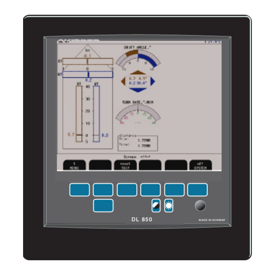
SKIPPER Electronics AS Chapter: 2. Operation Operation and Installation DL850 270 kHz 2. Operation When the installation is complete, and power is connected to the operator unit, the system is switched on/off by a power switch inside the cabinet. Fig. 1.1 Operator unit, panel layout. -
Page 11: Parameter Entry
Operation and Installation DL850 270 kHz Chapter: 2. Operation SKIPPER Electronics AS Parameter entry The fixed function buttons and the softkey buttons along with the rotating encoder, facilitates entry of parameters and other data. The following flowchart illustrates the procedure for changing settings. The various screens are shown in detail in the operation section. -
Page 12: Screen Pilot, Menu 1, Trip Reset
SKIPPER Electronics AS Chapter: 2. Operation Operation and Installation DL850 270 kHz The various softkey menus are selected by pressing repeatedly the MENU button on the left side of the softkey menu. The number on the button indicates present active menu. -
Page 13: Screen Pilot, Menu 2, System
Operation and Installation DL850 270 kHz Chapter: 2. Operation SKIPPER Electronics AS The various softkey menus are selected by pressing repeatedly the MENU button on the left side of the softkey menu. The number on the button indicates present active menu. -
Page 14: Screen Shallow Water, (Only In Non Docking Version)
SKIPPER Electronics AS Chapter: 2. Operation Operation and Installation DL850 270 kHz • Screen description “blue” shows resultant water speed and direction. • Screen description “brown” shows resultant SOG (speed over ground) and direction. (Note: Value should be close to GPS value). -
Page 15: Screen Docking, Arrow View (Only In Docking Version)
Operation and Installation DL850 270 kHz Chapter: 2. Operation SKIPPER Electronics AS If bottom track is present, the docking screen will show measured longitudinal and transversal speed over ground (SOG) at fore and calculated speed at stern point. Speed indication may either be presented by values and arrows, or values and bars for directions. -
Page 16: Screen Docking, Bar Graph View (Only In Docking Version)
SKIPPER Electronics AS Chapter: 2. Operation Operation and Installation DL850 270 kHz The screen above shows the result if ROT (Rate Of Turn) information is not available. Screen docking, bar graph view (only in docking version). Sofkey Name Range/value Default value... -
Page 17: Screen Open Sea, System
Operation and Installation DL850 270 kHz Chapter: 2. Operation SKIPPER Electronics AS Screen open sea, system. Softkey Name Range/value Default value Description Activate with hidden button Not used. Not used. Not used. Not used. Not used. SYSTEM On/Off Turn system off. -
Page 18: Setup And Function Control Screens
SKIPPER Electronics AS Chapter: 2. Operation Operation and Installation DL850 270 kHz Setup and Function Control Screens Each of the operation screens contains a graphic picture and one or more menu sets configured on the 6 softkey buttons. Manoeuvre to the setup and function control screens by keeping the screen select button pressed and rotating the encoder in either direction. -
Page 19: Enabling Advanced Parameters With Hidden Button
Operation and Installation DL850 270 kHz Chapter: 2. Operation SKIPPER Electronics AS Enabling advanced parameters with Hidden button To avoid accidental access to the internal settings, some advanced functions are disabled during normal operation. In order to enable them, do the following: •... -
Page 20: Screen Com, Menu 1, Nmea Setup
DISPLAY Output/input/off Input Selects the information (received from the external source or transmitted by the DL850) to be displayed on the screen. Output: Signals transmitted from DL850. Input: Signals received from external source. Off: No signals displayed on screen. -
Page 21: Screen Com, Menu 2, Nmea Com Setup
Operation and Installation DL850 270 kHz Chapter: 2. Operation SKIPPER Electronics AS Screen com, Menu 2, NMEA com setup. Softkey Name Range/value Default Description Activate value with hidden button MENU Menu 2 is selected. Choose COM port. BAUD 1200, 2400, 4800, 9600, 4800 Baud rate for chosen COM port. - Page 22 SKIPPER Electronics AS Chapter: 2. Operation Operation and Installation DL850 270 kHz The following examples show how the system responds to errors in the NMEA input formats. Formats in yellow are rejected. See “NMEA Setup” on page 48 for more informations about accepted formats.
-
Page 23: Screen Status, Menu 1, Units
Operation and Installation DL850 270 kHz Chapter: 2. Operation SKIPPER Electronics AS The status screen contains information that will facilitate analysis and correction of several problems. All installation settings are displayed on this screen. See section for trouble-shooting for more information about typical status screen content. -
Page 24: Screen Status, Menu 2, Date/Time
SKIPPER Electronics AS Chapter: 2. Operation Operation and Installation DL850 270 kHz Screen status, Menu 2, date/time. Softkey Name Range/value Default value Description Activate with hidden button MENU 1 - 8 Menu 2 is selected. Not used. YR.MONTH 00.01 - 31.12 Year and month setting. -
Page 25: Screen Status, Menu 4, Pulse Settings
Operation and Installation DL850 270 kHz Chapter: 2. Operation SKIPPER Electronics AS Screen status, Menu 4, pulse settings. Softkey Name Range/value Default value Description Active with hidden button MENU 1 - 8 Menu 4 is selected. OUT NUM 1 - 3... -
Page 26: Screen Status, Menu 6, Speed Limits And Hysteresis
Yes (3 beep) Screen status, Menu 8, speed test/simulate. Functions described below can be used during commissioning period to test different DL850 outputs with constant, user adjustable speed values. Note: When the test or simulator mode is activated, this will be indicated by flashing “Sim” label in the lower left part of the screen. -
Page 27: Screen Calibration, Menu 1, Auto Calibration
Operation and Installation DL850 270 kHz Chapter: 2. Operation SKIPPER Electronics AS For calibration, see: “5. Calibration procedure” on page 51. The calibration screen is default set to "Disabled". To enable calibration please see "Enabling of calibration" on page 52. -
Page 28: Screen Calibration, Menu 2, Manual Calibration
SKIPPER Electronics AS Chapter: 2. Operation Operation and Installation DL850 270 kHz Screen calibration, Menu 2, Manual calibration. Softkey Name Range/value Default Description Activate with value hidden button MENU 1 - 4 Menu 2 is selected. CALIBR NUM 1 - 5 Number on the calibration data set currently available for adjustments. -
Page 29: Screen Calibration, Menu 3, Mounting Settings
Operation and Installation DL850 270 kHz Chapter: 2. Operation SKIPPER Electronics AS Screen calibration, Menu 3, mounting settings. Softkey Name Range/value Default Description Activate with value hidden button MENU 1 - 4 Menu 3 is selected. Not used. SALINITY 20-35... -
Page 30: Screen Diagnostics, Menu 1, Details Off
SKIPPER Electronics AS Chapter: 2. Operation Operation and Installation DL850 270 kHz Screen diagnostics, Menu 1, Details Off. Soft- Name Range/ Default Description Activate value value with hidden button MENU 1 - 3 DIAGNOSTIC On/off Start self diagnostics procedure, The results will be shown in the ‘test results’... -
Page 31: Screen Diagnostics, Menu 1, Details On
Operation and Installation DL850 270 kHz Chapter: 2. Operation SKIPPER Electronics AS Screen diagnostics, Menu 1, Details On. Soft- Name Range/ Default Description Activate value value with hidden button MENU 1 - 3 DIAGNOSTIC On/off Start self diagnostics procedure, The results will be shown in the ‘test results’... -
Page 32: Screen Diagnostics, Menu 2, Filtering/Averaging
SKIPPER Electronics AS Chapter: 2. Operation Operation and Installation DL850 270 kHz Screen diagnostics, Menu 2, filtering/averaging. Soft- Name Range/ Default Description Activate value value with hidden button MENU 1 - 3 Menu 2 is selected. FILTER Low, Medium Selects speed filtering parameters. Run Aver: This is a simple... -
Page 33: Principal Functions
Bottom Track Characteristics DL850 will try to acquire a bottom track when the depth is between 2 and ca. 150 m, depending on the bottom conditions. In this case, both bottom track and water track data will be acquired. - Page 34 Built in test (BIT) is a function that runs a series of tests to try to find known errors within the system. There are 3 built in test in the DL850. “Screen status” “Link to transceiver” Automatic test of communication Display-Transceiver.
-
Page 35: User Maintenance
Operation and Installation DL850 270 kHz Chapter: 3. User Maintenance SKIPPER Electronics AS 3. User Maintenance Transducer Maintenance The transducers are virtually maintenance free, but occasional cleaning may be necessary to remove growth/shell (The acoustic signal may be decreased if extensive shell grow on sensor) -
Page 36: Installation
SKIPPER Electronics AS Chapter: 4. Installation Operation and Installation DL850 270 kHz 4. Installation This chapter contains information related to installation of the Doppler speed log. Please ensure you perform all the following subsections: • Installation of bottom parts/transducer. See •... -
Page 37: Location
Operation and Installation DL850 270 kHz Chapter: 4. Installation SKIPPER Electronics AS Location • The transducer must be install in foreship. • Optimal system operation is achieved by fitting the transducer as deep as possible on the hull. • The transmitting surface of the transducer must be installed horizontal. -
Page 38: Ac Voltage Selection
SKIPPER Electronics AS Chapter: 4. Installation Operation and Installation DL850 270 kHz For daily operation, these switches may stay on and the unit is switched off by pressing the “SYSTEM off” button. The unit is switched on by pressing any button. -
Page 39: Back-Up Battery Jumper Jp200
Operation and Installation DL850 270 kHz Chapter: 4. Installation SKIPPER Electronics AS Fig. 4.2 Static Memory Battery Jumper, I/O Board. Back-up Battery Jumper JP200 The battery back up memory on I/O PCB is not in use from SW version 4.03.04 and up. Refer to Fig. -
Page 40: Power Indication And Function Leds
SKIPPER Electronics AS Chapter: 4. Installation Operation and Installation DL850 270 kHz Fig. 4.3 Function LEDs, on terminal board Power indication and function LEDs The following LEDs are located on the terminal board: • LD400 NMEA signal activity on receive input 1. - Page 41 Operation and Installation DL850 270 kHz Chapter: 4. Installation SKIPPER Electronics AS Important note: If, after power-up, on screen status, you see the following message “Receiver PLD rev: 0.0.00” in the upper right corner, this is an indication of old PLD in the transceiver unit. The unit will work, but is not optimized.
-
Page 42: Operator Unit External Connections
SKIPPER Electronics AS Chapter: 4. Installation Operation and Installation DL850 270 kHz Operator unit External connections 5 x PG 13.5 cable entry 10-12 mm Ground Stud XJ402: NMEA ports D-SUB 9 pin female XCN6: VGA terminal HDD-SUB 15 pin female... -
Page 43: Operator Unit - Terminal Pcbconnections
Operation and Installation DL850 270 kHz Chapter: 4. Installation SKIPPER Electronics AS Operator unit - Terminal PCBconnections J100 Fig. 4.5 Terminal connections Edition: 2017-09-25 Page 43 of 92... -
Page 44: Examples Of Optocoupler I/O Connections
SKIPPER Electronics AS Chapter: 4. Installation Operation and Installation DL850 270 kHz Examples of optocoupler I/O connections Fig. 4.6 Misc I/O connections Page 44 of 92 Edition: 2017-09-25... -
Page 45: Alert Relay Connections
Operation and Installation DL850 270 kHz Chapter: 4. Installation SKIPPER Electronics AS Alert relay connections Power failure relay A relay is provided for interconnection to external alert systems. This relay is normally energized, and is released by power failure/power off. The terminals have the following significance:... -
Page 46: Log Pulse Outputs
SKIPPER Electronics AS Chapter: 4. Installation Operation and Installation DL850 270 kHz Log Pulse Outputs Pulse output terminals are as follows: • Each group of pulse outputs are galvanically separated. • All pulse outputs are opto couplers. • The pulse rates and output modes are programmable in “Screen status, Menu 4, pulse settings.”... -
Page 47: Inputs
Operation and Installation DL850 270 kHz Chapter: 4. Installation SKIPPER Electronics AS Inputs Pin nr Name Description J100 - 6 PLSREF Reference for pulse inputs. J100 - 7 PULSE 1 Not used. J100 - 8 PULSE 2 Not used. J100 - 9 INHIBREF Reference for inhib inputs. - Page 48 SKIPPER Electronics AS Chapter: 4. Installation Operation and Installation DL850 270 kHz NMEA interface Pin D-Type NMEA connector XJ402 in cabinet front NMEA Setup “Screen COM” is used for verification of received and control of transmitted IEC-61162-1:2007(E) (NMEA 0183) messages. See “Screen com, Menu 1, NMEA setup.”...
- Page 49 Operation and Installation DL850 270 kHz Chapter: 4. Installation SKIPPER Electronics AS NMEA senteces transmitted (talker) (IEC 61162-1:2007(E) (NMEA 0183) messages: Speed and distance Name Description Example Course over ground and $VDVTG,,,,,x.x,N,x.x,K,a*hh<CR><LF> ground speed Water speed and heading $VDVHW,,,,,x.x,N,x.x,K*hh <CR><LF>...
- Page 50 SKIPPER Electronics AS Chapter: 4. Installation Operation and Installation DL850 270 kHz Quality Name Description Example $PSKPVDSTA,<wsl>,<wst>,<bsl>,<bst>,<wal>,<bal><check Quality sum><CR LF A new proprietary NMEA message, indicating the quality of the information from the sensor has been imple- mented. The format is the following: <wsl>...
-
Page 51: Calibration Procedure
It is therefore necessary to calibrate speed logs once in place. SKIPPER speed logs have two parameters that need to be corrected by calibration. 1. Angular sensor installation error (heading error). 2. Speed variations due to drag or mounting tilt. -
Page 52: Calibration Routine
SKIPPER Electronics AS Chapter: 5. Calibration procedure Operation and Installation DL850 270 kHz Every vessel will drag some water when it moves. This occurs over the whole hull. As you move further from the hull, the effect of the ships movement gets less. -
Page 53: Step 1. Heading Error Correction
Operation and Installation DL850 270 kHz Chapter: 5. Calibration procedure SKIPPER Electronics AS Step 1. Heading error correction: The vessel sails a steady course in calm waters and the user reads the resultant angle (averaged drift). This is entered into the system using the Head err button and encoder on menu 3, and adjusted until the averaged drift angle is zero. -
Page 54: Step 2B. Semi Automatic Calibration
SKIPPER Electronics AS Chapter: 5. Calibration procedure Operation and Installation DL850 270 kHz Step 2b. Semi Automatic calibration: The vessel is made to sail a known distance and course in both directions. This to remove any water current factors from the speeds. - Page 55 Operation and Installation DL850 270 kHz Chapter: 5. Calibration procedure SKIPPER Electronics AS 2. Sail at a straight course in direction A to B and at a constant speed. When passing to point A, Press “START leg 1” on menu 1. The button text will change to stop and a calibrating warning will show on the screen.
-
Page 56: Trouble Shooting
SKIPPER Electronics AS Chapter: 6. Trouble Shooting Operation and Installation DL850 270 kHz 6. Trouble Shooting Symptom Cause Remedy Basic System Integrity No picture on LCD screen. 1. No AC or DC power to the system. Check switches and fuses on the 2. -
Page 57: Installation Problems
Operation and Installation DL850 270 kHz Chapter: 6. Trouble Shooting SKIPPER Electronics AS Symptom Cause Remedy Installation problems Status screen shows 1. Transceiver unit power is off. 1. Switch on the power in the Handshake (HSIN HSOUT). 2. A pair HSOUTA/HSOUTB on the transceiver unit or check fuses. -
Page 58: Interface Problems
Wrong polarity of input signals. Swap NMEA input lines. the NMEA input screen. NMEA input signals are listed in DL850 initialization. Cycle DL850 power / do a “factory the NMEA input screen, but not Irregular message mnemonic. Red: reset” after NMEA connection is accepted by the DL850. -
Page 59: Typical Status Screen Contents
If it is at all possible to cycle through the screens and observe this information, several assumptions may be made regarding operation of the DL850 system. Although some of the subsystems necessary for this basic system operation may still suffer from minor or intermittent operation disorders, the fact that it is possible to select and observe this screen, indicate correct operation of the following DL850 subsystems: 1. - Page 60 SKIPPER Electronics AS Chapter: 6. Trouble Shooting Operation and Installation DL850 270 kHz The information in the red box on previous page, shows the quality of the signals. • Link to Transceiver; shows the internal communication status between display unit and transceiver unit.
-
Page 61: Screen Diagnostics
Operation and Installation DL850 270 kHz Chapter: 6. Trouble Shooting SKIPPER Electronics AS Screen diagnostics This diagnostic screen is used for self test and diagnostics and recordings of the system The yellow area. Diagnostic self test results The red area. The Doppler frequencies and quality parameters The blue area. -
Page 62: Diagnostics
This test is included in software version 4.04.01 to identyfy an oscillation noise that can happen on the DL850 series manufactured before March 2017. (Serial # <17820) The system will try to interpret the the diagnostics test result in section “Possible reasons”... - Page 63 Operation and Installation DL850 270 kHz Chapter: 6. Trouble Shooting SKIPPER Electronics AS The blue area shows the results of the second stage filters which remove data that varies too far from the standard deviation. The filter type has a tConst (time constant) which is the number of pings used to approve a value (a form of rolling time average filter).
- Page 64 If the voltage drops considerably with the sensor power attached, the sensor is most likely faulty, although the power card is also suspected. If the problem is not identified here, refer to further instructions available as a data bulletin on the SKIPPER web site. Page 64 of 92...
-
Page 65: Recording Of Sensor Data
Take out Compact Flash (CF) memory card. Insert it into a PC CF card reader. Goto folder DL_REC In this folder copy the recorded file with todays date Send by mail to support@skipper.no together with a photo of “Screen status” and “Screen diagnostics”. Edition: 2017-09-25 Page 65 of 92... -
Page 66: Reset Factory Procedure
SKIPPER Electronics AS Chapter: 6. Trouble Shooting Operation and Installation DL850 270 kHz Reset factory procedure. In some cases the display cabinet may get “confused”, or the user has “adjusted” too much. Performing a “reset factory” procedure will return all values to factory default settings. -
Page 67: Specifications
Operation and Installation DL850 270 kHz Chapter: 7. Specifications SKIPPER Electronics AS 7. Specifications Dimensions Transducer, 3 beam 3 x 270 kHz D x H 99 x 115 mm. Mounting Sea valve/tank/retrofit. Cable length 40 m. Weight app. 10 kg (w/cable). -
Page 68: Environmental
SKIPPER Electronics AS Chapter: 7. Specifications Operation and Installation DL850 270 kHz Performance Speed range +/- 40 knots, (under favourable installation and sea conditions up to +/- 50 knots). Depth range for water track > 1.5 m. Maximum roll angle +/- 10 degrees. -
Page 69: Service
Operation and Installation DL850 270 kHz Chapter: 8. Service SKIPPER Electronics AS 8. Service • All service requests should be made to the local provider or representative. Contact details on title page. • Adjustments and repairs should only be performed by qualified service engineers. -
Page 70: Miscellaneous Installation Diagrams
SKIPPER Electronics AS Chapter: 10. Appendix 1 Operation and Installation DL850 270 kHz 10. Appendix 1 Miscellaneous Installation Diagrams Following diagrams, drawings and pictures are included: • Fig. 10.1. Picture of transceiver unit showing PCB positions. See “PCB positions in Transceiver Unit”... -
Page 71: Pcb Positions In Transceiver Unit
Operation and Installation DL850 270 kHz Chapter: 10. Appendix 1 SKIPPER Electronics AS PCB positions in Transceiver Unit Receiver Transmitter Xceiver Power Back Plane Fig. 10.1 PCB positions in Transceiver Unit Edition: 2017-09-25 Page 71 of 92... -
Page 72: Leds On Pcbs In Transceiver Unit
DL850 Transmitter for display unit manual.vsd LD 200: +5V LD201: +9V LD202: -9V LD101: System On LD100: DC Raw Fig. 10.2 LEDs on PCBs in Transceiver Unit DL850 Xceiver Power for display unit manual.vsd Page 72 of 92 Edition: 2017-09-25 DL850 Xceiver Power.vsd... -
Page 73: Dl 850 System Overview
Operation and Installation DL850 270 kHz Chapter: 10. Appendix 1 SKIPPER Electronics AS DL 850 System Overview Fig. 10.3. System overwiev Edition: 2017-09-25 Page 73 of 92... -
Page 74: Operator Unit - Transceiver Unit Interconnection
SKIPPER Electronics AS Chapter: 10. Appendix 1 Operation and Installation DL850 270 kHz Operator Unit - Transceiver Unit Interconnection Fig. 10.4. Transceiver unit - operator unit interconnection Page 74 of 92 Edition: 2017-09-25... -
Page 75: 270 Khz Sensor Cable Connection
Operation and Installation DL850 270 kHz Chapter: 10. Appendix 1 SKIPPER Electronics AS 270 kHz Sensor Cable Connection Fig. 10.5. 270 kHz Sensor Cable Connection Edition: 2017-09-25 Page 75 of 92... -
Page 76: Ferrite On Ac Power Input
SKIPPER Electronics AS Chapter: 10. Appendix 1 Operation and Installation DL850 270 kHz Ferrite on AC power input The transceiver unit is supplied with a ferrite EMC kit to be mounted on the AC power cable. The supplied ferrite has an inner diameter of 9mm. -
Page 77: Transceiver Unit Dimensions
Operation and Installation DL850 270 kHz Chapter: 10. Appendix 1 SKIPPER Electronics AS Transceiver Unit Dimensions DL850Transceiver Outline Dimensions Fig. 10.6. Transceiver Unit Dimensions Edition: 2017-09-25 Page 77 of 92... -
Page 78: Dimensional Drawing Cabinet
SKIPPER Electronics AS Chapter: 10. Appendix 1 Operation and Installation DL850 270 kHz Dimensional Drawing Cabinet Fig. 10.7. Cabinet Dimensions Page 78 of 92 Edition: 2017-09-25... -
Page 79: 115/230 V Selection On Backplane Inside Transceiver Unit
Operation and Installation DL850 270 kHz Chapter: 10. Appendix 1 SKIPPER Electronics AS 115/230 V selection on backplane inside Transceiver Unit If the AC power system is 115 V, the Transceiver unit may be prepared for 115 V AC by re-connecting the connectors J102, J103 as shown in figure 10.8. -
Page 80: Upgrading Software
11. Appendix 2 Upgrading Software New software versions are released from time to time. The DL850 with Compact Flash (CF) can be updated by performing the following software upgrade procedure. 1. If you have received a programmed compact flash, skip stage 2. -
Page 81: Cpu Pca-6742Ve Setup
Operation and Installation DL850 270 kHz Chapter: 11. Appendix 2 SKIPPER Electronics AS CPU PCA-6742VE setup • Connect a PC keyboard and a VGA screen to the CPU board. • Switch “On” the unit while pressing “Delete” key on the PC keyboard. -
Page 82: 12. Appendix 3. Non Wheelmark Approved Features
SKIPPER Electronics AS Chapter: 12. Appendix 3. Non wheelmark approved features Operation and Installation DL850 270 kHz 12. Appendix 3. Non wheelmark approved features In this appendix we will describe the functions only enabled after 3 beeps (about 12sec) pressing the hidden key. -
Page 83: Gps:bt
Operation and Installation DL850 270 kHz Chapter: 12. Appendix 3. Non wheelmark approved features SKIPPER Electronics AS GPS:BT This softkey allows the user to substitute longitudinal BT value with GPS data if bottom track is lost. The transversal value will be fixed to 0 knots. -
Page 84: 13. Appendix 4. Non Wheelmark Approved S Version
SKIPPER Electronics AS Chapter: 13. Appendix 4. Non wheelmark approved S version Operation and Installation DL850 270 kHz 13. Appendix 4. Non wheelmark approved S version S-version of operator unit The standard operator unit is a wheelmark approved navigational speed log. -
Page 85: 14. Appendix 5. Experimental Features
Operation and Installation DL850 270 kHz Chapter: 14. Appendix 5. Experimental features SKIPPER Electronics AS 14. Appendix 5. Experimental features This Appendix covers some experimental features. The features are accessed by the “hidden button”. “Screen diagnostics” “Menu 4” (NMEA-Raw, Current, Long samples and Beam filter) “Screen Calibration”, “Menu 4”... -
Page 86: Current Function
SKIPPER Electronics AS Chapter: 13. Appendix 4. Non wheelmark approved S version Operation and Installation DL850 270 kHz Current function The current in water may be calculated by the difference of STW (Speed through water) and SOG (Speed over ground). -
Page 87: Beam Filter
Operation and Installation DL850 270 kHz Chapter: 13. Appendix 4. Non wheelmark approved S version SKIPPER Electronics AS Beam filter In case the noise test (in “Screen diagnostics”) test failed on one channel this feature will let you filter away the faulty channel and let the speed log operate on the two working chanels. -
Page 88: Higher Accuracy Of Depth And Speed Calculation
SKIPPER Electronics AS Chapter: 13. Appendix 4. Non wheelmark approved S version Operation and Installation DL850 270 kHz Higher accuracy of depth and speed calculation The transducer calculates the beam angle into the sea based on type of transducer and sea condition. -
Page 89: Naut Rules
SKIPPER Electronics AS NAUT rules The DL850 will, by default, measure the “speed through water” (STW) from doppler effect in water particles in a distance 1 to 15 meters away from sensor. This is depending of depth as area will decrease to avoid bottom signal in shallow water. -
Page 90: 15. Index
SKIPPER Electronics AS Chapter: 15. Index Operation and Installation DL850 270 kHz 15. Index Symbols 115/230 V selection on backplane inside Transceiver unit 77 EMC 74 115/230 V selection on Combo Terminal board 37 Enabling advanced parameters with Hidden button 19... - Page 91 Operation and Installation DL850 270 kHz Chapter: 15. Index SKIPPER Electronics AS Installation 36 Principal Functions 33 Installation Diagrams 68 PULSES NUM 25 Installation of bottom parts/transducer 36 Installation problems 57 Interface problems 58 Receiver PLD rev: 0.0.00 41 Interfacing 9...
- Page 92 SKIPPER Electronics AS Chapter: 15. Index Operation and Installation DL850 270 kHz SPD LIMIT 26 SPD TEST 26 Speed Limit function 46 Standard System Supply 36 START 27 System 23 SYSTEM 12, 13, 14, 15, 16, 17 System Summary 6, 7...
Need help?
Do you have a question about the DL850 and is the answer not in the manual?
Questions and answers