Sign In
Upload
Download
Table of Contents
Contents
Add to my manuals
Delete from my manuals
Share
URL of this page:
HTML Link:
Bookmark this page
Add
Manual will be automatically added to "My Manuals"
Print this page
×
Bookmark added
×
Added to my manuals
Manuals
Brands
Skipper Manuals
Marine Equipment
EML1100
User manual
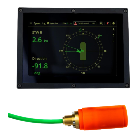
Skipper EML1100 User Manual
Electromagnetic speed log
Hide thumbs
1
2
Table Of Contents
3
4
5
6
7
8
9
10
11
12
13
14
15
16
17
18
19
20
21
22
23
24
25
26
27
28
29
30
31
32
33
34
35
36
37
38
39
40
41
42
43
44
page
of
44
Go
/
44
Contents
Table of Contents
Bookmarks
Table of Contents
EML1100/1200 Electromagnetic Speed Log
User Manual
Table of Contents
S- Introduction
S- EML Principle of Operation
Terminology
Units
Abbreviations
Alert Symbols
C- Physical Installation
H- Installation of the Screen
H - Connection of the System
Power Requirements
F- Installation of the Sensor and Metalwork
Integration to the Vessels Navigation System
C- System Selection on Startup
C- Connecting to the Bridge Network
C- Setup of Users and Options
C- Setup of Users
C- Setup of the System Options
C- Setup Screens and Configuration of the System
C- Set up of the Network, Serial and Other Communications (Communication Setup)
S- Output Formats
C-Accepted Inputs
S- Auxilliary Outputs
C- Setup of the System Parameters
C-Setup of Alerts
S- Calibration
C- Status
S Installation Angle
C- Temperature Offset
C- Auto Calibration
S-Verifying, Supporting and Maintenance of Your System
S- Diagnostic Screen
C- Hardware Reset Button
S- Calibration Check
C- Logging Screen
S- Periodical Maintenance of the System
C- Runtime Displays and Setup
C- Runtime Screens
The Runtime Setup
Retrofitting to an Older System
Getting Started Guide
Getting Started
User Quick Start
Vessel Speed
Advertisement
Quick Links
Download this manual
Document status Link to Spec owner Last edit
1 - author
EML1100/1200 Electromagnetic speed log
User Manual
Part number DM-I001-1.5.2023 Preliminary
Software version 1.0.0
PC
4 May 23
1
Table of
Contents
Previous
Page
Next
Page
1
2
3
4
5
Advertisement
Table of Contents
Need help?
Do you have a question about the EML1100 and is the answer not in the manual?
Ask a question
Questions and answers
Related Manuals for Skipper EML1100
Marine Equipment Skipper ED 161 Operator's Manual
Navigation sounder (16 pages)
Marine Equipment Skipper ESN100 Operation And Installation Manual
Single channel dual frequency echo sounder (42 pages)
Marine Equipment Skipper ESN100 Operation And Installation Manual
Single channel dual frequency echo sounder (56 pages)
Marine Equipment Skipper ESN200 Operation And Installation Manual
Dual channel multi frequency echo sounder (47 pages)
Marine Equipment Skipper ESN200 Operation And Installation Manual
Dual channel multi frequency echo sounder (61 pages)
Marine Equipment Skipper EML224N-SA Operation And Installation Manual
Graphic display stw navigational speed log (64 pages)
Marine Equipment Skipper EML1200 User Manual
Electromagnetic speed log (44 pages)
Marine Equipment Skipper IR301 Operation And Installation Manual
Digital depth repeater (9 pages)
Marine Equipment Skipper GDS101 Operation And Installation Manual
Graphic depth sounder (70 pages)
Marine Equipment Skipper DL850 Operation And Installation Manual
2 axis doppler log (73 pages)
Marine Equipment Skipper DL850 Operation And Installation Manual
270 khz, 2 axis doppler navigational, sog plus stw speed log (92 pages)
Marine Equipment Skipper GDS101 Replacement Procedure
(14 pages)
Marine Equipment Skipper GDS101 Quick Start Manual
Navigation echo sounder (2 pages)
Marine Equipment Skipper DL850-270 Getting Started
Doppler log (7 pages)
This manual is also suitable for:
Eml1200
Table of Contents
Print
Rename the bookmark
Delete bookmark?
Delete from my manuals?
Login
Sign In
OR
Sign in with Facebook
Sign in with Google
Upload manual
Upload from disk
Upload from URL


Need help?
Do you have a question about the EML1100 and is the answer not in the manual?
Questions and answers