Sign In
Upload
Manuals
Brands
Skipper Manuals
Marine Equipment
DL850
Skipper DL850 Doppler Speed Log Manuals
Manuals and User Guides for Skipper DL850 Doppler Speed Log. We have
3
Skipper DL850 Doppler Speed Log manuals available for free PDF download: Operation And Installation Manual
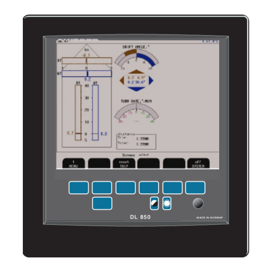
Skipper DL850 Operation And Installation Manual (92 pages)
270 kHz, 2 Axis Doppler Navigational, SOG Plus STW Speed Log
Brand:
Skipper
| Category:
Marine Equipment
| Size: 11 MB
Table of Contents
Table of Contents
3
Contents
6
Terminology
6
Units
6
Abbreviations
6
Introduction
7
System Overview
7
Sensor (Transducer)
8
Transceiver Unit
8
Interfacing
9
Outputs
9
Inputs
9
Alarts
9
Operator Unit
9
Operation
10
Screen Select
10
Parameter Entry
11
Primary Screens
11
Screen Pilot, Menu 1, Trip Reset
12
Screen Pilot, Menu 2, System
13
Screen Shallow Water, (Only in Non Docking Version)
14
Screen Docking, Arrow View (Only in Docking Version)
15
Screen Docking, Bar Graph View (Only in Docking Version)
16
Screen Open Sea, System
17
Setup and Function Control Screens
18
Enabling Advanced Parameters with Hidden Button
19
Screen Com, Menu 1, NMEA Setup
20
Screen Com, Menu 2, NMEA Com Setup
21
Screen Status, Menu 1, Units
23
Screen Status, Menu 2, Date/Time
24
Screen Status, Menu 3, Boat Setup/Buzzer
24
Docking Option Parameter Setup
24
Screen Status, Menu 4, Pulse Settings
25
Screen Status, Menu 5, Analogue Settings
25
Screen Status, Menu 6, Speed Limits and Hysteresis
26
Screen Status, Menu 7, Signal Good/Signal Suspected
26
Screen Status, Menu 8, Speed Test/Simulate
26
Screen Calibration, Menu 1, Auto Calibration
27
Screen Calibration, Menu 2, Manual Calibration
28
Screen Calibration, Menu 3, Mounting Settings
29
Screen Calibration, Menu 4, Mounting Settings
29
Screen Diagnostics, Menu 1, Details off
30
Screen Diagnostics, Menu 1, Details on
31
Screen Diagnostics, Menu 2, Filtering/Averaging
32
Screen Diagnostics, Menu 3, BT Settings
32
Principal Functions
33
Doppler Log Principle
33
Bottom Track Characteristics
33
Water Track Characteristics
33
Non-Volatile Parameter Memory
33
User Maintenance
35
Transducer Maintenance
35
Installation
36
Handling Warning
36
Location
37
Operator Unit Installation
37
115/230 V Selection on Combo Terminal Board Inside Display Unit
37
AC Voltage Selection
38
Fuses
38
Back-Up Battery Jumper JP200
39
Power Indication and Function Leds
40
Operator Unit External Connections
42
Operator Unit - Terminal Pcbconnections
43
Examples of Optocoupler I/O Connections
44
Alert Relay Connections
45
Power Failure Relay
45
Log Pulse Outputs
46
Speed Limit Function
46
Inputs
47
Analogue Interfaces
47
NMEA Interface
47
Options
47
Repeaters/Slaves
47
Calibration Procedure
51
Calibration Routine
52
Enabling of Calibration
52
Step 1. Heading Error Correction
53
Step 2A. Manual Speed Calibration/Adjustment
53
Step 2B. Semi Automatic Calibration
54
Trouble Shooting
56
Basic System Integrity
56
Installation Problems
57
Interface Problems
58
Basic Functionality
58
Typical Status Screen Contents
59
Screen Diagnostics
61
Diagnostics
62
Recording of Sensor Data
65
Reset Factory Procedure
66
Master Reset Procedure
66
Specifications
67
Dimensions
67
Functional Properties
67
Environmental
68
Service
69
Miscellaneous Installation Diagrams
70
Appendix 1
70
PCB Positions in Transceiver Unit
71
Leds on Pcbs in Transceiver Unit
72
DL 850 System Overview
73
Operator Unit - Transceiver Unit Interconnection
74
270 Khz Sensor Cable Connection
75
Ferrite on AC Power Input
76
Transceiver Unit Dimensions
77
Dimensional Drawing Cabinet
78
115/230 V Selection on Backplane Inside Transceiver Unit
79
Upgrading Software
80
Appendix 2
80
CPU PCA-6742VE Setup
81
12. Appendix 3. Non Wheelmark Approved Features
82
Echo Sounder Function
82
Gps:bt
83
13. Appendix 4. Non Wheelmark Approved S Version
84
S-Version of Operator Unit
84
14. Appendix 5. Experimental Features
85
NMEA-Raw
85
Current Function
86
Beam Filter
87
Higher Accuracy of Depth and Speed Calculation
88
NAUT Rules
89
15. Index
90
Advertisement
Skipper DL850 Operation And Installation Manual (80 pages)
2 Axis Doppler Speed Log 270 kHz
Brand:
Skipper
| Category:
Boating Equipment
| Size: 3 MB
Table of Contents
Table of Contents
3
Introduction
6
System Summary
6
Sensor (Transducer) and Transceiver
6
Operator Unit
7
Interfacing
7
Outputs
7
Inputs
7
Alarms
7
Operation
10
Parameter Entry
10
Primary Screens
11
Screen Pilot, Menu 1, Trip/Speed Alarm
12
Screen Pilot, Menu 2, System
13
Screen Shallow Water, (Only in Non Docking Version)
14
Screen Docking, Arrow View (Only in Docking Version)
15
Screen Docking, Bar Graph View (Only in Docking Version)
16
Screen Open Sea, System
17
Setup and Function Control Screens
18
Screen Com, Menu 1, NMEA Setup
19
Screen Com, Menu 2, NMEA Com Setup
20
Screen Status, Menu 1, Units
22
Screen Status, Menu 2, Date/Time
23
Screen Status, Menu 3, Boat Setup/Buzzer
23
Screen Status, Menu 4, Pulse Settings
24
Screen Status, Menu 5, Analogue Settings
24
Screen Status, Menu 6, Speed Limits and Hysteresis
25
Screen Status, Menu 7, Signal Good/Signal Suspected
25
Screen Status, Menu 8, Speed Test/Demo (Simulate)
25
Screen Calibration, Menu 1, Calibration
26
Screen Calibration, Menu 2, Manual Override
27
Screen Calibration, Menu 3, Mounting Settings
27
Screen Diagnostics, Menu 1
28
Screen Diagnostics, Menu 2, Fi Ltering/Averaging
29
Screen Diagnostics, Menu 3, Settings
29
Principal Functions
30
Doppler Log Principle
30
Water Track Characteristics
30
Echo Sounder Option
30
Non-Volatile Parameter Memory
31
Fixed Key Functions
31
Screen Select
31
Backlight Adjustment (Brightness)
31
Day/Night
31
Soft Key Functions
32
Speed Limits Functionality
32
User Maintenance
34
Transducer Maintenance
34
Operator Unit and Transceiver Unit Maintenance
34
Installation
35
Handling Warning
35
Transducer Installation
36
Location
36
Operator Unit Installation
36
115/230 V Selection on Combo Terminal Board
36
AC Voltage Selection
37
Fuses
37
Back-Up Battery Jumper JP200
38
Power Indication and Function Leds
39
Interfacing
41
Alarm Relay
41
Log Pulse Outputs
41
Inputs
42
Analogue Interfaces
42
NMEA Interface
42
Options
42
Repeaters/Slaves
42
External Interface Ports
43
Operator Unit - Connecting External Equipment
44
Operator Unit - Terminal Connections
45
Misc I/O Connections
46
Alarm Connections
47
Start-Up and System Adaption
48
System Adaption
48
Analogue Outputs and Log Pulse Outputs Range Selection
48
Units of Measure
48
NMEA Setup
48
Doppler Log Transmitted (Talker) (IEC 61162-1:2007(E) (NMEA 0183) Messages
49
Docking Option Parameter Setup
50
Calibration Procedure
51
Calibration Routine
52
Activation of the Hidden Menus
52
Step 1. Heading Error Correction
53
Step 2A. Manual Speed Calibration/Adjustment
53
Step 2B. Semi Automatic Calibration
54
Trouble Shooting
56
Basic System Integrity
56
Installation Problems
57
Interface Problems
58
Basic Functionality
58
Typical Status Screen Contents
59
Typical Diagnostic Screen Contents
61
Master Reset Procedure
64
Specifications
65
Dimensions
65
Functional Properties
65
Performance
66
Environmental
66
Service
67
10 Appendix 1
68
10. APPENDIX 1 Miscellaneous Installation Diagrams
68
PCB Positions in Transceiver Unit
69
Leds on Pcbs in Transceiver Unit
70
DL 850 System Overview
71
Operator Unit - Transceiver Unit Interconnection
72
270 Khz Sensor Cable Connection
73
Transceiver Unit Dimensions
74
Dimensional Drawing Cabinet
75
115/230 V Selection on Backplane Inside Transceiver Unit
76
12 Appendix 2
77
12. Appendix 2
77
Upgrading Software
77
CPU PCA-6742VE Setup
78
13 Appendix 3
79
13. Appendix 3
79
The Echo Sounder Function
79
Screen Pilot, Menu 1, Trip/Speed Alarm
79
Screen Pilot, Menu 2, es Mode Settings
80
Screen Diagnostics, Menu 3, es Mode, SL BT Mode, GPS->BT
80
Skipper DL850 Operation And Installation Manual (73 pages)
2 Axis Doppler Log
Brand:
Skipper
| Category:
Marine Equipment
| Size: 2 MB
Table of Contents
Introduction
5
I Nterfacing
6
Operation
7
O Peration S Creens
8
S Creen Nmea/C Ommunication
14
S Creen Status
16
S Creen Calibration
19
Creen Cope
21
Doppler Log Principle
25
Power ON/OFF
26
Screen Select
27
Clock and Calendar Settings
28
Simulator
29
User Maintenance
30
T Rouble S Hooting
31
T Ypical S Tatus S Creen C Ontents
32
T Ypical O Scilloscope S Creen C Ontents
34
Installation
37
Fig.4.4 Voltage Selection Connectors and Fuses, Terminal Board
39
Back-Up Battery Jumper 200
40
Power Indication and Function Led´s
41
I Nterfacing
43
NMEA Interface
44
I Nstallation Trouble Shooting
45
Start-Up and System Adaption
46
Dl850 Calibration Procedure
48
I Nstallation Angular Error Correction
49
M Anual Adjustment of Calibration Table
51
Specifications
52
P Erformance
53
Service
54
Appendix
55
Gate Valve Operation and Installation Manual
63
Advertisement
Advertisement
Related Products
Skipper DL1-Multi
Skipper DL1
Skipper DL2
Skipper DB-100-SB
Skipper DL21
Skipper DL2SDR-SB
Skipper DL850S27DR-SB
Skipper DB-100-SA
Skipper ED 161
Skipper EML1100
Skipper Categories
Marine Equipment
Control Unit
Car Navigation system
Accessories
Touch Panel
More Skipper Manuals
Login
Sign In
OR
Sign in with Facebook
Sign in with Google
Upload manual
Upload from disk
Upload from URL