SEW-Eurodrive Movitrac LTP-B Operating Instructions Manual
Standard inverters
Hide thumbs
Also See for Movitrac LTP-B:
- Operating instructions manual (132 pages) ,
- Compact operating instructions (48 pages) ,
- Manual (48 pages)

Related Manuals for SEW-Eurodrive Movitrac LTP-B


Summary of Contents for SEW-Eurodrive Movitrac LTP-B
-
Page 1: Operating Instructions
*25813137_0818* Drive Technology \ Drive Automation \ System Integration \ Services Operating Instructions Standard Inverters ® MOVITRAC LTP-B Edition 08/2018 25813137/EN... - Page 2 SEW-EURODRIVE—Driving the world...
-
Page 3: Table Of Contents
Table of contents Table of contents General information........................ 8 About this documentation .................... 8 Structure of the safety notes ................... 8 1.2.1 Meaning of signal words ................ 8 1.2.2 Structure of section-related safety notes............ 8 1.2.3 Structure of embedded safety notes .............. 8 Rights to claim under limited warranty ................ 9 Content of the documentation.................. 9 Exclusion of liability...................... 9... - Page 4 Table of contents 4.4.4 Operation on an IT system................ 27 4.4.5 Permitted voltage supply systems.............. 28 4.4.6 Help card ...................... 28 4.4.7 Removing the terminal cover ............... 29 4.4.8 Connecting and installing the braking resistor .......... 31 4.4.9 Motor temperature protection TF, TH, KTY84, PT1000 ....... 32 4.4.10 Multi-motor drive/group drive ...............
- Page 5 Table of contents 5.5.4 Troubleshooting and optimizing the hoist function ........ 77 Fire mode/emergency mode .................. 78 Operation at the 87 Hz characteristic (50 Hz motors)........... 79 Examples of analog input scaling and offset setting ............. 80 5.8.1 Example 1: Analog input scaling .............. 80 5.8.2 Example 2: Analog input offset ..............
- Page 6 Table of contents 7.4.7 Table of CANopen-specific objects ............ 109 7.4.8 Table of manufacturer-specific objects ............ 111 7.4.9 Emergency code objects ................ 111 Service ........................... 112 Electronics Service by SEW‑EURODRIVE.............. 112 Extended storage...................... 113 Waste disposal...................... 113 Parameters .......................... 114 Overview of parameters.................... 114 9.1.1 Parameters for realtime monitoring (read only)..........
- Page 7 Table of contents 11.2.1 Storage requirements................. 203 11.2.2 Installation requirements ................ 203 11.2.3 Requirements on the external safety controller.......... 205 11.2.4 Requirements for safety relays .............. 206 11.2.5 Requirements on startup ................ 206 11.2.6 Requirements on operation................ 206 11.3 Connection variants .................... 208 11.3.1 General information..................
-
Page 8: General Information
General information About this documentation General information About this documentation This documentation is an integral part of the product. The documentation is written for all employees who assemble, install, start up, and service this product. Make sure this documentation is accessible and legible. Ensure that persons respons- ible for the machinery and its operation as well as persons who work on the product independently have read through the documentation carefully and understood it. -
Page 9: Rights To Claim Under Limited Warranty
General information Rights to claim under limited warranty Rights to claim under limited warranty Read the information in this documentation. This is essential for fault-free operation and fulfillment of any rights to claim under limited warranty. Read the documentation before you start working with the product. Content of the documentation The current version of the operating instructions is the original. -
Page 10: Safety Notes
Safety notes Preliminary information Safety notes Preliminary information The following general safety notes serve the purpose of preventing injury to persons and damage to property. They primarily apply to the use of products described in this documentation. If you use additional components, also observe the relevant warning and safety notes. -
Page 11: Designated Use
Safety notes Designated use Specialist for elec- Any electrotechnical work may only be performed by electrically skilled persons with a trotechnical work suitable education. Electrically skilled persons in the context of this documentation are persons familiar with electrical installation, startup, troubleshooting, and maintenance of the product who possess the following qualifications: •... -
Page 12: Functional Safety Technology
Safety notes Functional safety technology Functional safety technology The product must not perform any safety functions without a higher-level safety sys- tem, unless explicitly allowed by the documentation. Transport Inspect the shipment for damage as soon as you receive the delivery. Inform the ship- ping company immediately about any damage. -
Page 13: Restrictions Of Use
Safety notes Electrical connection 2.7.1 Restrictions of use The following applications are prohibited unless explicitly permitted: • Use in potentially explosive areas • Use in areas exposed to harmful oils, acids, gases, vapors, dust, and radiation • Operation in applications with impermissibly high mechanical vibration and shock loads in excess of the regulations stipulated in EN 61800-5-1 •... -
Page 14: Protective Separation
Safety notes Protective separation Protective separation The product meets all requirements for protective separation of power and electronics connections in accordance with EN 61800-5-1. To ensure protective separation, all connected circuits must also meet the requirements for protective separation. 2.10 Startup/operation Observe the safety notes in the chapters "Startup"... -
Page 15: Device Structure
Device structure Nameplate Device structure Nameplate The following figure shows an example of a nameplate. 27021611319513483 Type designation Example: MCLTP-B 0015-2B1-4-00 (60 Hz) ® Product name MCLTP MOVITRAC LTP-B Version Version status of the device series Recommended motor 0015 0015 = 1.5 kW power Connection voltage 2 = 200 – 240 V... - Page 16 Device structure Type designation Country-specific design (60 Hz) 60 Hz design ® Operating Instructions – MOVITRAC LTP-B...
-
Page 17: Device Structure Of The Standard Inverter
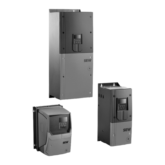
Device structure Device structure of the standard inverter Device structure of the standard inverter 3.3.1 Inverters with degree of protection IP20/NEMA 1 The following inverters have the housing shown below: Nominal line voltage Power of the inverter 230 V 0.75 – 5.5 kW 400 V 0.75 –... -
Page 18: Inverters With Degree Of Protection Ip66/Nema 4X
Device structure Device structure of the standard inverter 3.3.2 Inverters with degree of protection IP66/NEMA 4X The following inverters have the housing shown below: Nominal line voltage Power of the inverter 230 V 0.75 – 4 kW 400 V 0.75 – 7.5 kW 575 V 0.75 –... -
Page 19: Inverters With Degree Of Protection Ip55/Nema 12K
Device structure Device structure of the standard inverter 3.3.3 Inverters with degree of protection IP55/NEMA 12K The following inverters have the housing shown below: Nominal line voltage Power of the inverter 230 V 5.5 – 75 kW 400 V 11 – 160 kW 575 V 15 –... -
Page 20: Installation
Installation General information Installation General information • Carefully check the inverter for damage before the installation. • Store the inverter in its original packaging until it is used. The storage location must be clean and dry with an ambient temperature between ‑40 °C and +60 °C. •... -
Page 21: Permitted Tightening Torques
Installation Permitted tightening torques Permitted tightening torques Tightening torque in Nm for inverter Power of the inverter Control terminals Power terminals Nominal line voltage 230 V 0.75 – 2.2 kW 3 – 5.5 kW (IP20) 1 (IP20) 3 – 4 kW (IP66) 1 (IP66) 5.5 kW (IP66) 4 (IP66) 7.5 –... -
Page 22: Mechanical Installation
Installation Mechanical installation Mechanical installation 4.3.1 IP20 housing: Installation and installation space Inverters with degree of protection IP20 must be installed in a control cabinet. Observe the following requirements: • The control cabinet must be made of a heat conductive material unless it has forced cooling. -
Page 23: Ip55/Ip66 Housing: Installation And Control Cabinet Dimensions
Installation Mechanical installation 4.3.2 IP55/IP66 housing: Installation and control cabinet dimensions Inverters with degree of protection IP55/IP66 can be used indoors. In control cabinets or in field, the following minimum distances must not be underrun. 9007208910888971 Power of the inverter A in mm B in mm 230 V... -
Page 24: Electrical Installation
Installation Electrical installation Electrical installation WARNING Electric shock due to charged capacitors. Dangerous voltage levels may still be present inside the device and at the terminals up to 10 minutes after disconnection from the power supply. Severe or fatal injuries. • Wait 10 minutes after you have de-energized the inverter and have switched off the line voltage and the DC 24 V voltage. -
Page 25: Line Contactors
Installation Electrical installation • Do not loop the ground connections of the inverter from one inverter to the other. Neither route the ground connections to the inverters from other inverters. • The impedance of the ground circuit must comply with the local safety regulations of the industrial sector. -
Page 26: Mains Fuses
Installation Electrical installation 4.4.3 Mains fuses Fuse types: • Line protection types in operation classes gL, gG: – Nominal fusing voltage ≥ nominal line voltage – The nominal fusing current must be designed for at least 100% of the inverter nominal input current depending on the inverter utilization. -
Page 27: Operation On An It System
Installation Electrical installation 4.4.4 Operation on an IT system IP20 devices can be operated on the IT system as described below. The IT system version without Filter LTP-B...-15 should be used for the 3 × 380 – 480 V devices in the unit design IP55/IP66. Please contact SEW‑EURODRIVE for all other devices. For operation on the IT system, the connection of the overvoltage protection and the EMC filter to PE has to be separated. -
Page 28: Permitted Voltage Supply Systems
Installation Electrical installation 4.4.5 Permitted voltage supply systems • Voltage supply systems with grounded star point Inverters with all degrees of protection are intended for operation on TN and TT systems with directly grounded star point. • Voltage supply systems with non-grounded star point Operation on voltage supply systems with a non-grounded star point (for example IT systems) is only permitted for inverters with IP20 degree of protection and in- verters of device variant LTP-B...-15. -
Page 29: Removing The Terminal Cover
Installation Electrical installation 4.4.7 Removing the terminal cover The front cover of the inverter must be removed to access the terminals of inverters with degree of protection IP55/IP66. Only use cross-head or slot screwdrivers to open the terminal cover. The terminals can be accessed when the marked screws on the front of the product are removed as shown below. - Page 30 Installation Electrical installation Inverters with degree of protection IP55/NEMA 12K The following inverters have the housing shown below: Nominal line voltage Power of the inverter 230 V 5.5 – 75 kW 400 V 11 – 160 kW 575 V 15 – 110 kW 9007212609488907 • 230 V: 5.5 –...
-
Page 31: Connecting And Installing The Braking Resistor
Installation Electrical installation 4.4.8 Connecting and installing the braking resistor WARNING Danger of electric shock. The supply cables to the braking resistors carry a high DC voltage (approx. DC 900 V) during nominal operation. Severe or fatal injuries. • Before removing the supply cable, disconnect the inverter from the power supply and wait at least 10 minutes. -
Page 32: Motor Temperature Protection Tf, Th, Kty84, Pt1000
Installation Electrical installation 4.4.9 Motor temperature protection TF, TH, KTY84, PT1000 Motors with internal temperature sensor (TF, TH, KTY84, PT1000 or similar) can be directly connected to the inverter. If the thermal protection is triggered, the inverter displays the error "F-PTC". For motor protection monitoring, the following types can be selected: •... -
Page 33: Multi-Motor Drive/Group Drive
Installation Electrical installation 4.4.10 Multi-motor drive/group drive • The total of the motor currents must not exceed the nominal current of the inverter. The maximum permitted cable length for the group is limited to the values of single connection. See chapter "Technical data" (→ 2 174). •... -
Page 34: Information Regarding Ul
Installation Electrical installation 4.4.12 Information regarding UL INFORMATION Due to UL requirements, the following chapter is always printed in English independ- ent of the language of the documentation. Ambient Temperature The units in IP20 are suitable for an ambient temperature of 50 °C, max. 60 °C. The units in IP55/IP66 are suitable for an ambient temperature of 40 °C, max 50 °C. - Page 35 Installation Electrical installation 3 × 200 – 240 V devices Devices Fuses or MCB (type B) Max. supply short cir- Max. line voltage cuit current 0008 10 A 0015 15 A 0022 17.5 A 0030 30 A 0040 30 A 0055 40 A 0075 50 A 0110 70 A 100 kA rms (AC) 240 V 0150 90 A...
- Page 36 Installation Electrical installation 3 × 500 – 600 V devices Devices Fuses or MCB (type B) Max. supply short cir- Max. line voltage cuit current 0008 6 A 0015 6 A 0022 10 A 0040 10 A 0055 15 A 0075 20 A 0110 30 A 0150 35 A 0185 45 A 100 kA rms (AC) 600 V 0220...
-
Page 37: Electromagnetic Compatibility (Emc)
Installation Electrical installation 4.4.13 Electromagnetic compatibility (EMC) Inverters with EMC filters are designed for use in machines and drive systems. They meet the EMC product standard EN 61800-3 for drives with variable speed. Observe the specifications of Directive 2014/30/EU for EMC‑compliant installation of the drive system. - Page 38 Installation Electrical installation General information about connecting the motor shield For all applications with a expectedly higher EMC load, using shielded cables is re- commended. The shield must be connected as follows: Connect the shield by the shortest possible route and make sure it is grounded over a wide area at both ends.
- Page 39 Installation Electrical installation Example LTP-B inverter Example LTP-B inverter with LTX module 25249678731 [1] Motor cable [5] Control cables [2] Additional PE connection [6] • 230 V: 0.75 – 2.2 kW • 400 V: 0.75 – 4 kW • 575 V: 0.75 – 5.5 kW [3] Encoder cable [7] •...
- Page 40 Installation Electrical installation Recommendation for applying the motor shield to inverters with IP55/IP66 The use of metal screw fittings is recommended to connect the motor shield to the device. For the inverters listed below, the threads must be at least 8 mm. Inverters with de- The following inverters have the housing shown below: gree of protection...
- Page 41 Installation Electrical installation LTP-B LTP-B + LTX 9007212157811595 [1] Metal counter nut [4] LTX module [2] Metal cable gland [5] Motor cable [3] Enclosed rubber gasket [6] Supply system cable ® Operating Instructions – MOVITRAC LTP-B...
- Page 42 Installation Electrical installation Recommendation for routing the encoder, control and communication cables 9007212386365579 [1] Encoder cable, if LTX module [4] Signal terminal/communication [2] Signal terminal/communication [5] Supply system cable [3] Motor cable Inverters with de- The following inverters have the housing shown below: gree of protection Nominal line voltage Power of the inverter...
-
Page 43: Overview Of Signal Terminals
Installation Electrical installation The following inverters have the housing shown below: Nominal line voltage Power of the inverter 230 V 22 – 75 kW 400 V 45 – 160 kW 575 V 55 – 110 kW 18243537675 [1] Supply system cable [2] Metal cable gland [3] Motor cable 4.4.14... - Page 44 Installation Electrical installation INFORMATION When the inputs of the inverter are supplied by an external 24 V voltage supply or PLC, the GND reference potential must be connected to terminals 7 and 9. The con- trol electronics of the inverter operate isolated. If the STO is driven by an external voltage supply, wire it according to the connection examples shown in chapter "Disconnection of a single drive" (→ 2 209) The following switching thresholds apply to all digital and multi-functional inputs that...
- Page 45 Installation Electrical installation The response time of the digital and analog inputs is less than 4 ms. The resolution of the analog inputs is 12 Bit at an accuracy of ±2% in reference to the set maximum scaling. ® Operating Instructions – MOVITRAC LTP-B...
-
Page 46: Communication Socket Rj45
Installation Electrical installation Relay terminals NOTICE Possible damage to property Do not connect any inductive loads to the relay contact. Ter- Signal Relay function selec- Description minal tion Relay output 1 reference P2-15 Relay contact (AC 250 V / DC 30 V, max. -
Page 47: Backup Mode
Installation Electrical installation 4.4.16 24 V backup mode 24 V backup mode is not necessary for simple operation. Wiring is therefore not ne- cessary. In order to ensure fieldbus communication via a fieldbus interface in the event of a power failure, back up the inverter externally with 24 V. Requirements Firmware version 1.20 (can be seen in P0-28). -
Page 48: Dc Link Connection
Installation Electrical installation 4.4.17 DC link connection The DC link is routed on terminals for all power ratings. It is thus possible to couple all devices with a DC link connection or to directly supply them with DC voltage. Contact SEW‑EURODRIVE in such a case. ®... -
Page 49: Wiring Diagram
Installation Wiring diagram Wiring diagram WARNING Danger of electric shock. Incorrect wiring can lead to dangerously high voltages. Severe or fatal injuries. • Adhere to the following. In the following applications, always cut-off the brake in the AC and DC circuits: •... - Page 50 Installation Wiring diagram L2/N F11/F12/F13 (AC-3) L1 L2 ND LT.. L1' L2' L3' L1 L2 L3 MOVITRAC LT.. 9007217635508875 Line contactor between grid and inverter. Brake Main switch (only for unit design IP66/NEMA 4x housing with switch (MC LTP- B..-40)) Connection of BW../BW..T braking resistor Bimetallic relay for protection of the braking resistor * not with 1-phase 230 V ®...
-
Page 51: Brake Control
Installation Wiring diagram 4.5.1 Brake control V DC (BMV) V AC V AC (BMK) V AC F14/F15 F14/F15 F14/F15 (A C-3) (A C-3) C-3) (A C-3) (AC-3) white white BM K BG E BG E blue BM V white DR/DT/DV: DR/DT/DV: blue Cut-off in the DC... -
Page 52: Startup
Startup User interface Startup User interface 5.1.1 Keypads The inverters in IP20 design are equipped with a standard keypad. The inverters in IP55/IP66 design are equipped with a full text display with language switching function. Both keypads allow for operation and setup of the inverter without additional devices. Standard keypad 9007202188405387 [1] 6-digit 7-segment display... - Page 53 Startup User interface Operation Both keypads have 5 keys with the following functions: Start [2] • Enable drive • Changing the direction of rotation • Stop drive Stop [3] • Acknowledge error Navigate [4] • Switch menu • Save parameter values •...
-
Page 54: Resetting Parameters To Default Settings
Startup User interface 5.1.2 Resetting parameters to default settings The following preconditions must be satisfied for the parameters to be reset to the fac- tory setting: • The inverter must not be enabled. • The inverter must not be in fire mode/emergency mode. •... -
Page 55: Software Lt Shell
Startup User interface 5.1.4 Software LT Shell The LT Shell software enables an easy and quick startup of the inverters. It is avail- able for download on the SEW‑EURODRIVE website. After the installation, perform software updates on a regular basis. In combination with the engineering package (cable set C) and the USB11A interface adapter, the inverter can be connected to the software. - Page 56 Startup User interface ® Bluetooth LTP-B L1/L L2/N L3 1 2 3 4 5 6 7 8 9 10 11 12 13 14 15 16 17 18 9007216440559755 Parameter module ® Operating Instructions – MOVITRAC LTP-B...
-
Page 57: Movitools ® Motionstudio Engineering Software
Startup User interface ® 5.1.5 MOVITOOLS MotionStudio engineering software The software can be connected to the inverter as follows: • Via an SBus-connection between PC and inverter. A CAN dongle is required. A prefabricated cable is not available and must be manufactured according to the RJ45 assignment and the inverter interface. - Page 58 Startup User interface USB11A Cable splitter RJ10 to RJ10 cable Cable USB A-B RJ45 cable with open end RJ45 Ethernet cable ® Operating Instructions – MOVITRAC LTP-B...
-
Page 59: Automatic Measuring Procedure "Auto Tune
Startup Auto tune Auto tune Automatic measuring procedure "Auto tune" With the automatic measuring procedure, the inverter can measure almost any motor to determine the motor data. • After a reset to the factory settings, the measuring procedure starts automatically after the first enable and takes up to 2 minutes depending on the control type. -
Page 60: Startup With Asynchronous Motors With V/F Control
Startup Startup for motors 5.3.1 Startup with asynchronous motors with V/f control 1. Connect the motor to the inverter. Adhere to the nominal motor voltage when con- necting. 2. Enter the motor data indicated on the motor nameplate: • P1-07 = Nominal voltage of the motor •... -
Page 61: Startup With Asynchronous Motors Or Torque Motors With Vfc Torque Control
Startup Startup for motors 5.3.3 Startup with asynchronous motors or torque motors with VFC torque control 1. Connect the motor to the inverter. Adhere to the nominal motor voltage when con- necting. 2. Enter the motor data indicated on the motor nameplate: •... -
Page 62: Starting With Synchronous Motors Without Encoder Feedback (Pmvc Control)
Startup Startup for motors 5.3.4 Starting with synchronous motors without encoder feedback (PMVC control) The synchronous motors are permanent magnet motors. INFORMATION The operation of synchronous motors without encoder must be checked in a test ap- plication. Stable operation in this operating mode cannot be ensured for all applica- tion cases. -
Page 63: Startup With Lspm Motors From Sew-Eurodrive
Startup Startup for motors 5.3.5 Startup with LSPM motors from SEW‑EURODRIVE DR..J type motors are motors with LSPM technology (Line Start Permanent Magnet motors). 1. Connect the motor to the inverter. During the connection, adhere to the nominal motor voltage. 2. -
Page 64: Startup With Synchronous Reluctance Motors (Syn-R Control)
Startup Startup for motors 5.3.6 Startup with synchronous reluctance motors (SYN-R control) 1. Connect the motor to the inverter. Adhere to the nominal motor voltage when con- necting. 2. Enter the motor data indicated on the motor nameplate: • P1-07 = Nominal voltage of the motor •... -
Page 65: Startup With Brushless Dc Motors (Bldc Control)
Startup Startup for motors 5.3.7 Startup with brushless DC motors (BLDC control) 1. Connect the motor to the inverter. Adhere to the nominal motor voltage when con- necting. 2. Enter the motor data indicated on the motor nameplate: • P1-07 = Internal voltage at nominal motor speed •... -
Page 66: Startup With Preset Motors From Sew-Eurodrive
Startup Startup for motors 5.3.8 Startup with preset motors from SEW‑EURODRIVE Startup can be performed if one of the following CMP.. motors (speed class 4500 min ) or MGF..-DSM motors (speed class 2000 min ) is connected to the in- verter: Motor type Display... - Page 67 Startup Startup for motors INFORMATION "Auto Tune" is not necessary for preset motors. If a CMP.. motor with an electronic nameplate is connected to the inverter, P1-16 is selected automatically. If a MGF..-DSM is selected, the upper torque limit in P4-07 is automatically set to 200%.
-
Page 68: Startup Of The Control Signal Source
Startup Startup of the control signal source Startup of the control signal source WARNING Installing sensors or switches at the terminals may cause an enable signal. The mo- tor may start up automatically. Severe or fatal injuries. • Make sure that no persons are within the reach of moving parts of the system. •... -
Page 69: Keypad Mode (P1-12 = 1 Or 2)
Startup Startup of the control signal source 5.4.2 Keypad mode (P1-12 = 1 or 2) For operation in keypad mode: • Set P1-12 to "1" (uni-directional) or "2" (bi-directional). • Connect a jumper or switch between terminals 1 and 2 on the terminal block to en- able the inverter. - Page 70 Startup Startup of the control signal source The following figure shows the configuration options for the PID controller. 36028800023251339 ® Operating Instructions – MOVITRAC LTP-B...
- Page 71 Startup Startup of the control signal source General informa- Connect the sensor for the controlled variable to analog input 1 or 2 depending on tion on the use P3-10. You can scale the sensor value using parameter P3-12 in such a way that the value is indicated on the inverter display with the proper quantity, for example 0 ...
-
Page 72: Master-Slave Mode (P1-12 = 4)
Startup Startup of the control signal source 5.4.4 Master-slave mode (P1-12 = 4) Master Slave 1 Slave 2 L1/L L2/N L3 L1/L L2/N L3 L1/L L2/N L3 1 2 3 4 5 6 7 8 9 10 11 12 13 1 2 3 4 5 6 7 8 9 10 11 12 13 1 2 3 4 5 6 7 8 9 10 11 12 13 IOIOI... -
Page 73: Fieldbus Mode (P1-12 = 5, 6 Or 7)
Startup Startup of the control signal source Parameter description Master Slave settings settings P2-28 (speed scaling) – User-defined P2-29 (Scaling factor) – User-defined Configuration for load distribution Load distribution is supported only with the following operating modes/motor controls: P4-01 = 0, 3, 6, 7, 8 Parameter description Master settings Slave settings... -
Page 74: Hoist Function
Startup Hoist function Hoist function The inverter is equipped with a hoist function. When the hoist function is active, all rel- evant parameters and functions are activated and locked, if necessary. For proper functioning, a correct motor startup has to be performed as described in chapter "Startup for hoist function" (→ 2 75). -
Page 75: General Information
Startup Hoist function 5.5.1 General information • Clockwise rotating field of the motor corresponds to upward direction. • Counterclockwise rotating field of the motor corresponds to downward direction. • Stop the motor to reverse the direction of rotation. To do so, activate the brake. Set the controller inhibit before you reverse the direction of rotation. -
Page 76: Hoisting Mode
Startup Hoist function 5.5.3 Hoisting mode The following diagram shows hoisting mode. Setpoint speed Brake release speed P2-07 Brake application speed P2-08 Enable (DI01) Mechanical brake Contact relay 2 18014401720170891 Inverter enable The motor runs up to brake release speed (fixed setpoint speed 7). -
Page 77: Troubleshooting And Optimizing The Hoist Function
Startup Hoist function 5.5.4 Troubleshooting and optimizing the hoist function SP-Err / ENC02: Increase the speed error window in P6-07 if this error message appears. In case of problems such as sagging of the hoist, check the following parameters and/ or adapt: P1-03/04 = Reduce ramp times, pass through slow speed ranges as quickly as... -
Page 78: Fire Mode/Emergency Mode
Startup Fire mode/emergency mode Fire mode/emergency mode In "Fire mode/emergency mode", the inverter drives the motor at the speed defined in P6-14. The inverter automatically resets all errors and ignores all setpoints, control signal sources and shutdowns (e.g.: External error or enable signal revoked). Opera- tion of the inverter is maintained for as long as possible. -
Page 79: Operation At The 87 Hz Characteristic (50 Hz Motors)
Startup Operation at the 87 Hz characteristic (50 Hz motors) Operation at the 87 Hz characteristic (50 Hz motors) The V/f ratio remains the same at 87 Hz operation. However, higher power and speeds are generated, which causes a higher current flow. 400 V 230 V 87 Hz 50 Hz... -
Page 80: Examples Of Analog Input Scaling And Offset Setting
Startup Examples of analog input scaling and offset setting Examples of analog input scaling and offset setting Analog input format, scaling and offset are connected to each other. Inverter setting: P1-01 = 50 Hz 5.8.1 Example 1: Analog input scaling Control 0 – 40 Hz with analog input 0 – 10 V: = 0 Hz, n = 40 Hz P2-31 = 80%... -
Page 81: Example 2: Analog Input Offset
Startup Examples of analog input scaling and offset setting 5.8.2 Example 2: Analog input offset Control 15 – 35 Hz with analog input 0 – 10 V: = 15 Hz, n = 35 Hz Offset P2-31 = 40%, P2-32 = -75% Analog input 13627144971 n - n −... -
Page 82: Example 3: Analog Input Scaling And Offset
Startup Examples of analog input scaling and offset setting 5.8.3 Example 3: Analog input scaling and offset Control 15 - 45 Hz with analog input 3 - 8 V: P2-31 = 120%, P2-32 = 5% Analog input 18364553227 − full range 2 31 −... -
Page 83: Fans And Pumps
Startup Fans and pumps Fans and pumps The following functions are available for applications with pumps or fans: • Voltage increase/boost (P1-11) • Adjustment of the V/f characteristic curve (P4-10, P4-11) • Energy-saving function (P1-06) • Flying start function (P2-26) •... - Page 84 Startup Motor potentiometer The following figure shows the basic function of the motor potentiometer. Maximum speed Fixed setpoint speed 1 Minimum speed Enable input source CW/CCW input source Motor potentiometer up input source Motor potentiometer down input source Fixed setpoint speed 1 input source 18014406340232971 Inverter enable...
-
Page 85: 3-Wire Control
Startup 3-wire control 5.11 3-wire control The function is activated via the digital input function selection P1-15 = 21. The 3-wire control principle determines the control. The enable and direction of rotation signals of the inverter then react edge controlled. •... -
Page 86: Operation
Operation Inverter status Operation Inverter status 6.1.1 Static inverter status The following list shows the status messages for a non-enabled inverter. Message Description StoP Power stage of inverter deactivated. This message is displayed when the motor is at an idle state and no error is present. -
Page 87: Operating State Of The Inverter
Operation Inverter status 6.1.2 Operating state of the inverter The following table shows the messages of the status for an enabled inverter. You can toggle between displaying the output frequency, output current, output power, and speed by briefly pressing the <Navigate> key on the keypad. Message Message Description... -
Page 88: Status Displays Of The Parameter Module
Operation Inverter status 6.1.3 Status displays of the parameter module The parameter module status is displayed on the inverter. Display Description PASS-r The parameter module has successfully read/saved the inverter parameters. OS-Loc The parameter module is locked. Attempt to read parameter from the frequency inverter with activated parameter module lock. -
Page 89: Troubleshooting
Operation Troubleshooting Troubleshooting Symptom Cause and solution Overload or overcurrent error of the Check the star/delta terminal connection in the motor. The nominal unloaded motor during acceleration operating voltage of motor and inverter must match. The delta con- nection always yields the lower voltage of a multi-voltage motor. Overload or overcurrent –... -
Page 90: Error List
Operation Error list Error list Code (in- Code Error code CANopen Meaning Measure verter dis- (MotionStudio status Emergency play) in P0-13) word Code if Bit5 = 1 4-20 F 0x71 0x1012 Signal loss 4 – • Check whether the input current lies within the range 20 mA (> 500 ms) defined in P2-30 and P2-33. - Page 91 Operation Error list Code (in- Code Error code CANopen Meaning Measure verter dis- (MotionStudio status Emergency play) in P0-13) word Code if Bit5 = 1 ® Enc-09 0x0E 0x1026 HIPERFACE type During the use of Smart Servo Package, a wrong motor/ is not supported.
- Page 92 Operation Error list Code (in- Code Error code CANopen Meaning Measure verter dis- (MotionStudio status Emergency play) in P0-13) word Code if Bit5 = 1 0x01 0x2303 Short-term over- Fault during stop procedure: current at the in- Check for premature brake application. verter output.
- Page 93 Operation Error list Code (in- Code Error code CANopen Meaning Measure verter dis- (MotionStudio status Emergency play) in P0-13) word Code if Bit5 = 1 O-Volt 0x07 0x3206 DC link over- The error occurs if a high flywheel load or overhauling voltage load is connected, and the excess regenerative energy is transferred back to the inverter.
- Page 94 Operation Error list Code (in- Code Error code CANopen Meaning Measure verter dis- (MotionStudio status Emergency play) in P0-13) word Code if Bit5 = 1 SC-F02 0x2F 0x1033 SBus/CANopen Check: communication • The communication connection between inverter and error external devices. •...
-
Page 95: Fieldbus Mode
Fieldbus mode General information Fieldbus mode A bus system makes it possible to adapt electronic drive technology components to the particulars of the machinery within wide limits. There is a risk that a change of parameters that cannot be detected externally may result in unexpected (but not un- controlled) system behavior and may have a negative impact on operational safety, system availability, or data security. - Page 96 Fieldbus mode General information Description Settings PO4 No function, freely configurable via P5-11 Process input words Description Settings Byte Status word 0 Output stage enable 0: Locked Low byte 1: Enabled Inverter ready 0: Not ready for operation 1: Ready PO data enabled 1, if P1-12 = 5 3 – 4...
-
Page 97: Communication Example
Fieldbus mode General information 7.1.2 Communication example The following information is sent to the inverter if: • The digital inputs have been configured and wired properly to enable the inverter. Description Value Description Control word 0x0000 Stop along the second deceleration ramp (P2-25). 0x0001 Coasting 0x0002... -
Page 98: Connecting The Signal Terminals At The Inverter
Fieldbus mode General information 7.1.4 Connecting the signal terminals at the inverter For bus mode, you can connect the signal terminals using the default setting of P1-15 as described in chapter "Overview of signal terminals" (→ 2 43). When the DI3 signal level changes, the system toggles between the speed setpoint source fieldbus (low) and fixed setpoint 1 (high). -
Page 99: Connecting A Gateway Or Controller (Sbus Movilink ® )
Fieldbus mode Connecting a gateway or a controller (SBus MOVILINK) Connecting a gateway or a controller (SBus MOV ILINK) ® Connecting a gateway or controller (SBus MOVILINK 7.2.1 Specification ® MOVILINK profile CAN/SBus application profile from SEW‑EURODRIVE specifically adjusted to SEW inverters. For detailed information, ®... -
Page 100: Startup At Gateway
Fieldbus mode Connecting a gateway or a controller (SBus MOVILINK) Wiring from the control to the "communication socket RJ45" (→ 2 46) of the inverter: Side view Designation Terminal at CCU/PLC Signal RJ45 socket Signal ® MOVI-PLC or Gate- X26:1 CAN 1H SBus/CAN bus h way (DFX/UOH) X26:2 CAN 1L... -
Page 101: Startup At A Ccu
Fieldbus mode Connecting a gateway or a controller (SBus MOVILINK) 7.2.4 Startup at a CCU Before taking the inverter into operation with "Drive Startup" in MotionStudio, you have to set the following parameters directly on the inverter: • Set parameter P1-14 to "1" to obtain access to the LTX-specific parameter group P1-01 –... -
Page 102: Modbus Rtu
Fieldbus mode Modbus RTU Modbus RTU The inverters support communication via Modbus RTU. The "Read Holding Register (03)" function is used for reading and the "Write Single Register (06)" function for writ- ing. The "Write Multiple Register (16)" function is also available for PA data word 1-5. To use Modbus RTU, configure the inverter as described in chapter "Parameter set- tings for the inverter" (→ 2 97). -
Page 103: Register Allocation Of The Process Data Words
Fieldbus mode Modbus RTU 7.3.3 Register allocation of the process data words The process data words are allocated to the Modbus registers shown in the table. The status and control words have a fixed allocation. The other process data words can be freely configured in parameter group P5-xx. -
Page 104: Data Flow Example
Fieldbus mode Modbus RTU 7.3.4 Data flow example In this example, the following parameters are read by the controller (PLC address base = 1): • P1-07 (rated motor voltage, modbus register 107) • P1-08 (rated motor current, modbus register 108). Request master → slave (Tx) Reading register Address... - Page 105 Fieldbus mode Modbus RTU Start address Register start address =0x0001 = 1 (first register to be written on = 2 PA2) Information 0700 (setpoint speed) 2 × CRC bytes CRC_high, CRC_low ® Operating Instructions – MOVITRAC LTP-B...
-
Page 106: Canopen
Fieldbus mode CANopen CANopen The inverters support communication via CANopen. For using CANopen, configure the inverter as described in chapter "Parameter settings for the inverter" (→ 2 97). Following a general overview of how to establish a communication connection via CANopen and the process data communication. The CANopen configuration is not de- scribed. -
Page 107: Supported Transmission Modes
Fieldbus mode CANopen 7.4.4 Supported transmission modes The various transmission types can be selected for every process data project (PDO) in the network management (NMT). The following transmission types are supported for Rx-PDOs: Rx PDO transmission mode Transmission Mode Description type 0 –... -
Page 108: Data Flow Example
Fieldbus mode CANopen 7.4.6 Data flow example Process data communication example with default setting: Word 1 Word 2 Word 3 Word 4 COB ID DB Byte 1 Byte 2 Byte 3 Byte 4 Byte 5 Byte 6 Byte 5 Byte 6 Description 0x701 "00"... -
Page 109: Table Of Canopen-Specific Objects
Fieldbus mode CANopen 7.4.7 Table of CANopen-specific objects CANopen-specific objects Index Sub in- Function Access Type PDO map Default value 1000h Device type Unsigned 32 1001h Error register Unsigned 8 1002h Manufacturer status register Unsigned 16 1005h COB-ID Sync Unsigned 32 00000080h 1008h Manufacturer device name... - Page 110 Fieldbus mode CANopen CANopen-specific objects Index Sub in- Function Access Type PDO map Default value 1A01h Tx PDO2 mapping / no. of entries Unsigned 8 Tx PDO2 1st mapped object Unsigned 32 21180010h Tx PDO2 2nd mapped object Unsigned 32 21190010h Tx PDO2 3rd mapped object Unsigned 32...
-
Page 111: Table Of Manufacturer-Specific Objects
Fieldbus mode CANopen 7.4.8 Table of manufacturer-specific objects The manufacturer-specific objects of the inverter are defined as follows: Manufacturer-specific objects Index Sub in- Function Access Type Note 2000h Reserved / no function Unsigned 16 Read as 0, writing not possible 2001h Integer 16 Defined as command... -
Page 112: Service
Service Electronics Service by SEW‑EURODRIVE Service To ensure fault-free operation, SEW-EURODRIVE recommends that you check the ventilation openings in the housing at regular intervals and clean them if necessary. Electronics Service by SEW‑EURODRIVE If you are unable to rectify a fault, contact SEW‑EURODRIVE Service. For the ad- dresses, refer to www.sew‑eurodrive.com. -
Page 113: Extended Storage
Service Extended storage Extended storage If the device is in extended storage, connect it to the line voltage for at least 5 minutes every 2 years. Otherwise, the device's service life may be reduced. Procedure when maintenance has been neglected: Electrolytic capacitors are used in the inverters. -
Page 114: Parameters
Parameters Overview of parameters Parameters Overview of parameters 9.1.1 Parameters for realtime monitoring (read only) Parameter group 0 gives access to internal inverter parameters for monitoring pur- poses. These parameters cannot be changed. Parameter group 0 is visible if P1-14 is set to "101" or "201". Para- CANope Modbus... - Page 115 Parameters Overview of parameters Para- CANope Modbus Description Indicating range Explanation meter n/SBus register index P0-28 11247 – Firmware version and e.g. "1 1.00", "1 4F3C" Firmware and check sum of the control electronics 11250 check sum "2 1.00", "2 Ed8A" and power section P0-29 11251 –...
- Page 116 Parameters Overview of parameters Para- CANope Modbus Description Indicating range Explanation meter n/SBus register index P0-55 Current voltage offset – Internal value (availab- Entry 1: Reference value phase W ility depends on power Entry 2: Current measured value output) P0-56 Max.
- Page 117 Parameters Overview of parameters Para- CANope Modbus Description Indicating range Explanation meter n/SBus register index P0-73 11354 Encoder status / error For incremental encoders: codes • 1=EnC-04 Signal A/A error • 2=EnC-05 Signal B/B error • 3=EnC-06 Signal A+B error For LTX HIPERFACE®...
-
Page 118: Parameter Register
Parameters Overview of parameters 9.1.2 Parameter register The following table lists all parameters together with their factory settings (in- dicated in bold). Numerical values are displayed with the complete setting range. Parameter CANopen/ Modbus Description Setting range SBus index register Factory setting P1-01 11020... - Page 119 Parameters Overview of parameters Parameter CANopen/ Modbus Description Setting range SBus index register Factory setting Lower user relay limit 2: Analog output 2 P2-20 11055 0.0 – P2-19 (→ 2 137) P2-21 11056 Display of scaling factor (→ 2 137) -30000 – 0.000 – 30000 P2-22 11057 Display of scaling source (→ 2 137)
- Page 120 Parameters Overview of parameters Parameter CANopen/ Modbus Description Setting range SBus index register Factory setting P4-10 11098 V/f characteristic adjustment frequency 0.0 – 100.0% of P1-09 (→ 2 150) V/f characteristic adjustment voltage P4-11 11099 0.0 – 100.0% of P1-07 (→ 2 151) P4-12 11100 Motor brake control (→ 2 151) 0: Deactivated...
- Page 121 Parameters Overview of parameters Parameter CANopen/ Modbus Description Setting range SBus index register Factory setting P6-16 11130 Analog output 1 offset (→ 2 159) -500.0 – 0.0 – 500.0% P6-17 11131 Max. torque limit timeout (→ 2 160) 0.0 – 0.5 − 25.0 sec. P6-18 11132 DC braking voltage level (→ 2 160) Auto, 0.0 –...
- Page 122 Parameters Overview of parameters Parameter CANopen/ Modbus Description Setting range SBus index register Factory setting P9-07 11177 Reset input source (→ 2 169) OFF, din-1 – din-8, On P9-08 11178 External fault input source (→ 2 169) OFF, din-1 – din-8, On Source for activating terminal control P9-09 11179 OFF, din-1 –...
-
Page 123: Explanation Of The Parameters
Parameters Explanation of the parameters Explanation of the parameters 9.2.1 Parameter group 1: Basic parameters (level 1) P1-01 Maximum speed Setting range: P1-02 – 50.0 Hz – 5 × P1-09 (max. 500 Hz) Specifies the upper limit for the frequency (speed) that can be applied to the motor in any operating mode. - Page 124 Parameters Explanation of the parameters P1-05 Stop mode Defines the delay behavior of the drive for normal operation and power failure. • 0: Stop ramp along the process P1-04 • 1: Coast, the motor runs down to an idle state in a non-controlled manner. P1-06 Energy saving function •...
- Page 125 Parameters Explanation of the parameters P1-09 Rated motor frequency Setting range: 25 – 50/60 – 500 Hz Specifies the rated frequency of the motor connected to the inverter (according to the motor nameplate). This is the frequency at which the maximum (rated) output voltage is applied to the motor.
- Page 126 Parameters Explanation of the parameters P1-12 Control signal source • 0: Terminal mode • 1: Keypad mode unipolar • 2: Keypad mode bipolar • 3: PID controller mode • 4: Slave mode ® • 5: SBus MOVILINK • 6: CANopen •...
- Page 127 Parameters Explanation of the parameters INFORMATION Individual configuration of digital inputs: To individually configure the digital input assignment, set parameter P1-15 to "0". The input terminals for DI1 – DI5 (with option DI1 – DI8) are thus set to "no function" and can be freely assigned via parameter group 9.
- Page 128 Parameters Explanation of the parameters P1-15 Digital input 1 Digital input 2 Digital input 3 Analog input 1/di- Analog input 2/di- Comments gital input 4 gital input 5 0: Stop 0: CW rotation 0: Open 0: Open 0: Decel. ramp P1-04 Fixed setpoint speed 1: Enable + start 1: CCW rotation...
- Page 129 Parameters Explanation of the parameters P1-15 Digital input 1 Digital input 2 Digital input 3 Analog input 1/di- Analog input 2/di- Comments gital input 4 gital input 5 0: Stop 0: Stop 0: Selected speed Speed setpoint ana- External error –...
- Page 130 Parameters Explanation of the parameters INFORMATION When using a TF/TH, KTY or PT1000, set P2-33 to PTC-th, KTY or PT1000. See also the connection information in chapter "Motor temperature protection TF, TH, KTY84, PT1000" (→ 2 32). ® Operating Instructions – MOVITRAC LTP-B...
-
Page 131: Parameter Group 1: Servo-Specific Parameters (Level 1)
Parameters Explanation of the parameters 9.2.2 Parameter group 1: Servo-specific parameters (level 1) P1-16 Motor type This parameter is intended only for startup of the Smart Servo package (LTX) or MGF..-DSM. The parameter must not be used in all other cases. This parameter is available for the following inverters: IP20 IP66... - Page 132 Parameters Explanation of the parameters Display value Motor type Explanation gF-2 MGF..2-DSM-B If a MGF..-DSM is selected, the torque limit in P4-07 is automatically set to 200%. This value has to be adapted in accordance with the gear unit ratio according to the documentation "Ad- gF-4 MGF..4-DSM-B dendum to the Operating Instructions, Drive Unit MGF..-DSM on LTP-B Inverter".
-
Page 133: Parameter Group 2: Extended Parameter Setting (Level 2)
Parameters Explanation of the parameters The inertia ratio between motor and connected load can be specified in this para- meter. This value can usually remain set to the default value "1.0". However, the iner- tia ratio is used by the control algorithm as precontrol value for CMP../synchronous motors from P1-16 to provide the optimal torque/current for accelerating the load. - Page 134 Parameters Explanation of the parameters P2-06 Fixed setpoint speed 6 Setting range: -P1-01 – 0.0 Hz – P1-01 Is also used as reference travel speed. P2-07 Fixed setpoint speed 7 Setting range: -P1-01 – 0.0 Hz – P1-01 Also used for brake release speed in hoist mode. P2-08 Fixed setpoint speed 8 Setting range: -P1-01 –...
- Page 135 Parameters Explanation of the parameters Analog output mode: 0 – 10 V or 0 / 4 – 20 mA Setting Function Explanation Motor speed (analog) The amplitude of the analog output signal represents the motor speed. It is scaled from 0 to the maximum speed limit defined in P1-01. Motor current (analog) The amplitude of the analog output signal represents the inverter output current (torque).
- Page 136 Parameters Explanation of the parameters P2-15/P2-20 Relay outputs The function of the relay outputs can be selected according to the table below. If a re- lay is controlled depending on a limit value, it reacts as follows: Relay closed Relay open lower limit upper limit 9007211969771275...
- Page 137 Parameters Explanation of the parameters P2-19 Upper user relay limit 2 / analog output 2 Setting range: 0.0 – 100.0 – 200.0% P2-20 Lower user relay limit 2 / analog output 2 Setting range: 0.0 – P2-19% P2-21/P2-22 Display scaling A user-defined display value can be scaled and shown on the display with the follow- ing two parameters P2-21/P2-22.
- Page 138 Parameters Explanation of the parameters Sizes 4 – 7: Coast – 0.1 – 2.0 – 6000 sec. Is selected automatically in the event of a power failure if P2-38 = 2. Can also be selected using digital inputs depending on other parameter settings. With setting "0", the motor coasts to a halt. P2-26 Flying start enable When the flying start function is enabled, the inverter first determines the current rotor speed.
- Page 139 Parameters Explanation of the parameters Additional scaling and offset examples can be found in chapter "Examples of analog input scaling and offset setting" (→ 2 80) 100% 100% Analog input 9007206625474443 P2-32 Analog input 1 offset Setting range: -500 – 0 – 500% Additional scaling and offset examples can be found in chapter "Examples of analog input scaling and offset setting" (→ 2 80) 100%...
- Page 140 Parameters Explanation of the parameters • 1: 10 – 0 V / unipolar voltage input • 2: PTC-th / motor thermistor input • 3: 0 – 20 mA / current input • 4: t4 – 20 mA / current input • 5: r4 – 20 mA / current input •...
- Page 141 Parameters Explanation of the parameters WARNING With the setting "Auto-0" and set enable signal, there is a danger of an automatic re- start of the drive after an error message has been acknowledged (reset) or after switch-on (voltage on). Fatal or severe injuries and damage to property •...
- Page 142 Parameters Explanation of the parameters Switchover behavior when the setpoint source switches to keypad mode: The motor speed changes to the minimum speed from P1-02. The motor speed changes to the last keypad speed set. The current motor speed is taken on after switchover. The motor speed changes to the fixed setpoint speed from P2-08.
-
Page 143: Parameter Group 3: Pid Controller (Level 2)
Parameters Explanation of the parameters 9.2.4 Parameter group 3: PID controller (level 2) P3-01 PID proportional gain Setting range: 0.0 – 1.0 – 30.0 PID Controller proportional gain. Higher values result in a greater change of the in- verter output frequency as response to minor changes of the feedback signal. If the value is too high, it can cause instability. - Page 144 Parameters Explanation of the parameters A value of 0.0% corresponds to the minimum speed limit defined in P1-02. P3-09 PID correcting variable limitation • 0: Fixed setpoint limit/PID output range limited by P3-07 and P3-08. • 1: Analog input 1 variable upper limit/PID maximum output limited by the signal present at analog input 1.
-
Page 145: Parameter Group 4: Motor Control (Level 2)
If P1-10 = 0 is set, the slip is not included in the calculation. This causes the motor to react very slightly to load changes and not have a tendency to vibrate. SEW EURODRIVE recommends this motor control for fans, pumps, and applic- ations with direct drive. - Page 146 Parameters Explanation of the parameters • 7: Synchronous reluctance motor speed control (SYN-R) Speed control for synchronous reluctance motors. • 8: Brushless DC motor speed control (BLCD) Speed control for brushless DC motors INFORMATION "Auto tune" must be performed after each operating mode/motor control change. If the "auto tune"...
- Page 147 Parameters Explanation of the parameters INFORMATION Controller optimization should always initially take place via parameter P7-10. This parameter affects parameters P4-03/P4-04 internally. P4-05 Motor power factor (cos phi) Setting range: 0.00, 0.50 – 0.99 Power factor on the motor nameplate P4-06 Torque reference/limit value source Function of the parameter, depending on operating mode/motor control Operating mode/motor...
- Page 148 Parameters Explanation of the parameters P4-07 – P4-09 Motor torque limit settings These parameters are used to adjust the torque limits of the motor. P4-09 P4-07 P4-08 P4-08 P4-07 P4-09 18014401982492939 ® Operating Instructions – MOVITRAC LTP-B...
- Page 149 Parameters Explanation of the parameters P4-07 Max. motor torque limit Setting range: P4-08 – 200 – 500% This parameter is used to set the upper torque limit. The limit value source is specified with parameter P4-06. Example 1: Asynchronous motors in V/f control In V/f control, the percentage apparent output current is limited, depending on P1-08.
- Page 150 Parameters Explanation of the parameters INFORMATION Use this parameter with the utmost care because the output frequency of the inverter will increase (to reach the torque) and the selected setpoint speed might be ex- ceeded. P4-09 Max. regenerative torque limit Setting range: P4-08 –...
- Page 151 Parameters Explanation of the parameters P4-11 V/f characteristic adjustment voltage Setting range: 0.0 – 100.0% of P1-07 P4-12 Motor brake control Enables the hoist function of the inverter. Parameters P4-13 through P4-16 are enabled. Relay contact 2 is set to hoist. The function cannot be changed. •...
-
Page 152: Parameter Group 5: Fieldbus Communication (Level 2)
Parameters Explanation of the parameters When P4-17 is disabled, the thermal overload memory is reset when switching power off and on again. When P4-17 is enabled, the memory is maintained even after power off and on again. For inverters that are operated with a line frequency of 50 Hz, the factory setting is 0 = disabled. - Page 153 Parameters Explanation of the parameters • 3: 57.6: 57600 Bd • 4: 115.2: 115200 Bd P5-04 Modbus RTU data format • 0: n-1: no parity, 1 stop bit • 1: n-2: no parity, 2 stop bits • 2: O-1: odd parity, 1 stop bit •...
- Page 154 Parameters Explanation of the parameters • 5: Analog output 1 (0x1000 = 100%) Digital output 1 (0x0001 = 24 V, other values = 0 V) • 6: Analog output 2 (0x1000 = 100%) Digital output 2 (0x0001 = 24 V, other values = 0 V) •...
- Page 155 Parameters Explanation of the parameters P5-12 Fieldbus PI2 definition Definition of input 2, 3, 4 for transmitted process data Parameter description like P5-12 – P5-14. P5-13 Fieldbus PI3 definition Definition of input 2, 3, 4 for transmitted process data Parameter description like P5-12 – P5-14 P5-14 Fieldbus PI4 definition Definition of input 2, 3, 4 for transmitted process data Parameter description like P5-12 –...
-
Page 156: Parameter Group 6: Extended Parameters (Level 3)
Parameters Explanation of the parameters P5-20 Relay 4 lower limit Setting range: 0.0 – 200.0% INFORMATION The function of expansion relay 5 is fixed to "Motor speed > 0". 9.2.7 Parameter group 6: Extended parameters (level 3) P6-01 Firmware upgrade enable Activates the firmware upgrade mode for the control electronics and/or the power elec- tronics. - Page 157 Parameters Explanation of the parameters If the value is too small, the digital output or relay “bounces”. 25162662027 Depending on the setting in P2-11, P2-13, P2-15, P2-18 Percentage hysteresis of P6-04 referred to P1-01 P6-05 Encoder feedback enable When set to "1", encoder feedback is enabled. This parameter is enabled automatical- ly as soon as an LTX module is connected.
- Page 158 Parameters Explanation of the parameters P6-09 Droop speed/load distribution control Setting range: 0.0 – 25.0% This function requires one motor for each inverter. In applications where several mo- tors drive a common load, but different motor loads occur due to mechanical reasons, this function can balance the load of individual motors.
- Page 159 Parameters Explanation of the parameters Do not use this function for servo applications or lifting applications. • 0: NC switching contact: The function is activated with logic 0. • 1: NO switching contact: The function is activated with logic 1. P6-14 Fire mode/emergency mode speed Setting range: -P1-01 –...
- Page 160 Parameters Explanation of the parameters This parameter specifies the offset in % used for analog output 1. 100% Analog output 100% -50% -100% 13089606539 P6-17 Max. torque limit timeout Setting range: 0.0 – 0.5 − 25.0 sec. This parameter defines how long the motor is operated above the torque limits (P4-07; P4-09) before the inverter is switched off by the torque monitoring (O-Torq).
- Page 161 Parameters Explanation of the parameters Sets the braking resistor power in kW with a resolution of 0.1 kW. This value is used for thermal protection of the braking resistor. When set to "0.0", the protection function for the braking resistor is disabled. P6-21 Brake chopper operating cycle at undertemperature Setting range: 0.0 –...
-
Page 162: Parameter Group 7: Motor Control Parameters (Level 3)
Parameters Explanation of the parameters The entire parameter settings are saved to a secured memory. Upon successful com- pletion of the backup, the display shows "USr-PS". The memory content is preserved, even when the device is de-energized and when the factory settings are activated. Selection 2: Deleting the saved parameterization from the secure memory. - Page 163 Parameters Explanation of the parameters For synchronous motors: Value has to be set to 0 ohm. P7-03 Motor stator inductance (Lsd) Setting range: (power-dependent) (H) For induction motors: Phase stator inductance value. For synchronous motors: Phase d-axis stator inductance in Henry. P7-04 Motor magnetization current (Id rms) Setting range: 10% ×...
- Page 164 Parameters Explanation of the parameters • To discharge the DC link, the frequency inverter delivers current (P7-09) and the motor accelerates again. • The DC link voltage falls below U again. Zmax • The motor is continued to be decelerated. P7-10 Stiffness (for vector control) Setting range: 0 –...
-
Page 165: Parameter Group 8: Application-Specific Parameters (Only Ltx) (Level 3)
Parameters Explanation of the parameters In addition, this parameter functions together with P7-12 to align the rotor. boost current = K x P7-14 y (x P7-15 2 x P7-15 18364580875 P7-15 Torque boost frequency limit Setting range: 0.0 – 50% Frequency range for the applied boost current (P7-14) in % of the rated motor fre- quency (P1-09). - Page 166 Parameters Explanation of the parameters P8-05 Reference travel type • 0: Disabled • 1: Zero pulse with negative travel direction • 2: Zero pulse with positive travel direction • 3: End of reference cam negative travel direction • 4: End of reference cam positive travel direction •...
-
Page 167: Parameter Group 9: Digital Inputs Defined By The User (Level 3)
Parameters Explanation of the parameters P8-12 Reference offset high word Setting range: 0 – 65535 P8-13 Reserved P8-14 Reference enable torque Setting range: 0 – 100 – 500% 9.2.10 Parameter group 9: Digital inputs defined by the user (level 3) The purpose of parameter group 9 is to give the user full flexibility to control the in- verter behavior in complex applications that require specific parameter settings. - Page 168 Parameters Explanation of the parameters Inverter display Setting Function Digital input 4 Function linked to digital input 4 (analog input 1) status. Digital input 5 Function linked to digital input 5 (analog input 2) status. Digital input 6 Function linked to digital input 6 (requires extended I/O op- tion).
- Page 169 Parameters Explanation of the parameters P9-02 Rapid stop input source Setting range: OFF, din-1, din-2, din-3, din-4, din-5, din-6, din-7, din-8, On This parameter specifies the source for the rapid stop. With a High signal, the motor stops along the ramp from P2-25. P9-03 Input source for clockwise rotation (CW) Setting range: OFF, din-1, din-2, din-3, din-4, din-5, din-6, din-7, din-8, On This parameter specifies the source for clockwise rotation (CW).
- Page 170 Parameters Explanation of the parameters P9-10 – P9-17 Setpoint source Up to 8 setpoint sources can be defined for the inverter and can be selected during operation using P9-18 – P9-20. When changing the setpoint source, the new source is applied immediately during ongoing operation.
- Page 171 Parameters Explanation of the parameters P9-18 – P9-20 Setpoint source selection input The active setpoint source can be selected and switched during operation with para- meters P9-18 – P9-20: P9-20 P9-19 P9-18 Setpoint source 1 (P9-10) 2 (P9-11) 3 (P9-12) 4 (P9-13) 5 (P9-14) 6 (P9-15) 7 (P9-16)
- Page 172 Parameters Explanation of the parameters P9-22 Fixed setpoint speed selection input 1 Setting range: OFF, din-1, din-2, din-3, din-4, din-5, din-6, din-7, din-8, On Logic source "Bit 1" for selection of the fixed setpoint speed. P9-23 Fixed setpoint speed selection input 2 Setting range: OFF, din-1, din-2, din-3, din-4, din-5, din-6, din-7, din-8, On Logic source "Bit 2"...
- Page 173 Parameters Explanation of the parameters The status of the limit switch is also depicted in the status word. P9-31 Negative limit switch CCW Setting range: OFF, din-1, din-2, din-3, din-4, din-5, din-6, din-7, din-8 The parameter defines the digital input for the negative limit switch. The switch must be wired as an NC contact with wire break monitoring.
-
Page 174: Technical Data
Technical data Markings Technical data 10.1 Markings The following table lists all markings that can be given on a nameplate or attached to the motor and an explanation of what they mean. Marking Meaning CE marking to state compliance with the Low Voltage Directive 2014/35/ EU directive 2011/65/EU (RoHS) serves for limiting the use of hazardous substances in electric and electronic equipment. -
Page 175: Ambient Conditions
Technical data Ambient conditions 10.2 Ambient conditions Ambient temperature range during -20 °C to +50 °C (IP20/NEMA 1) operation -20°°C to +40°°C (IP55/NEMA 12K) (For PWM frequency 2 kHz) -20 °C to +40 °C (IP66/NEMA 4X) Derating depending on the ambi- 2.5%/°C to 60 °C for the following inverters with degree of protection ent temperature IP20/NEMA 1: 230 V: 0.75 –... -
Page 176: 1-Phase System Ac 200 - 240 V
Technical data Technical data 10.3 Technical data The "Horsepower" (HP) specification is defined as follows: • 200 – 240 V devices: NEC2002, table 430-150, 230 V • 380 – 480 V devices: NEC2002, table 430-150, 460 V • 500 – 600 V devices: NEC2002, table 430-150, 575 V 10.3.1 1-phase system AC 200 –... - Page 177 Technical data Technical data ® MOVITRAC LTPB – EMC filter class C1 according to EN 61800-3 Power in kW 0.75 Maximum control terminal cross section mm² 0.05 – 2.5 30 – 12 1) Recommended values for UL compliance ® Operating Instructions – MOVITRAC LTP-B...
-
Page 178: 3-Phase System Ac 200 - 240 V
Technical data Technical data 10.3.2 3-phase system AC 200 – 240 V INFORMATION All inverters with a power supply of 3 × AC 200 – 240 V can also be operated with 1 × AC 200 – 240 V at device terminal L1 and L2 when observing a derating of 50% of the output current. - Page 179 Technical data Technical data Power 7.5 – 18.5 kW ® MOVITRAC LTPB – EMC filter class C2 according to EN 61800-3 Power in kW 18.5 IP55/NEMA 12K MC LTP-B.. 0075-2A3-4-10 0110-2A3-4-10 0150-2A3-4-10 0185-2A3-4-10 Part number 18251919 18251978 18252036 18252060 INPUT Nominal line voltage V according 3 ×...
- Page 180 Technical data Technical data Power 22 – 45 kW ® MOVITRAC LTPB – EMC filter class C2 according to EN 61800-3 Power in kW IP55/NEMA 12K MC LTP-B.. 0220-2A3-4-10 0300-2A3-4-10 0370-2A3-4-10 0450-2A3-4-10 Part number 18252087 18252117 18252141 18252176 INPUT Nominal line voltage V according 3 ×...
- Page 181 Technical data Technical data Power 55 – 75 kW ® MOVITRAC LTPB – EMC filter class C2 according to EN 61800-3 Power in kW IP55/NEMA 12K MC LTP-B.. 0550-2A3-4-10 0750-2A3-4-10 Part number 18252206 18252230 INPUT Nominal line voltage V according to EN 50160 3 × AC 200 – 240 ±10% line Line frequency f 50 / 60 ±5%...
-
Page 182: Phase System Ac 380 – 480 V
Technical data Technical data 10.3.3 3-phase system AC 380 – 480 V INFORMATION All inverters with a power supply of 3 × AC 380 – 480 V can also be operated with 1 × AC 380 – 480 V at device terminal L1 and L2 when observing a derating of 50% of the output current. - Page 183 Technical data Technical data ® MOVITRAC LTPB – EMC filter class C2 according to EN 61800-3 Power in kW 0.75 Maximum device 10 / 16 terminal cross 8 / 6 section Maximum control 0.05 – 2.5 terminal cross 30 – 12 section 1) Recommended values for UL compliance 2) IP20 housing: Size 3 / IP55 housing: Size 4 ®...
- Page 184 Technical data Technical data Power 15 – 37 kW ® MOVITRAC LTPB – EMC filter class C2 according to EN 61800-3 Power in kW 18.5 IP55/NEMA 12K MC LTP-B.. 0150-5A3-4-10 0185-5A3-4-10 0220-5A3-4-10 0300-5A3-4-10 0370-5A3-4-10 Part number 18252044 18252079 18252095 18252125 18252168 INPUT Nominal line voltage V 3 × AC 380 – 480 ±10% line cording to EN 50160...
- Page 185 Technical data Technical data Power 45 – 90 kW ® MOVITRAC LTPB – EMC filter class C2 according to EN 61800-3 Power in kW IP55/NEMA 12K MC LTP-B.. 0450-5A3-4-10 0550-5A3-4-10 0750-5A3-4-10 0900-5A3-4-10 Part number 18252184 18252214 18252249 18252273 INPUT Nominal line voltage V 3 × AC 380 – 480 ±10% line cording to EN 50160...
- Page 186 Technical data Technical data Power 110 – 160 kW ® MOVITRAC LTPB – EMC filter class C2 according to EN 61800-3 Power in kW IP55/NEMA 12K MC LTP-B.. 1100-5A3-4-10 1320-5A3-4-10 1600-5A3-4-10 Part number 18252303 18252311 18252346 INPUT Nominal line voltage V according to 3 × AC 380 – 480 ±10% line EN 50160...
-
Page 187: 3-Phase System Ac380 - 480 V As An It System Version - Device Without Filter
Technical data Technical data 10.3.4 3-phase system AC380 - 480 V as an IT system version - device without filter INFORMATION The listed inverters have no EMC filter and are only suitable for IT systems. The technical data correspond to the 3 × 380 – 480 V standard devices with the ex- ception of the filter class. -
Page 188: Phase System Ac 500 – 600 V
Technical data Technical data 10.3.5 3-phase system AC 500 – 600 V INFORMATION All inverters with a power supply of 3 × AC 500 – 600 V can also be operated with 1 × AC 500 – 600 V at device terminal L1 and L2 when observing a derating of 50% of the output current. - Page 189 Technical data Technical data Power 7.5 – 30 kW ® MOVITRAC LTP-B Power in kW 18.5 IP20/NEMA 1 MC LTP-B.. 0075-603-4-00 0110-603-4-00 0150-603-4-00 – – – Part number 18410855 18410863 18410871 – – – IP66/NEMA 4X housing without IP55/NEMA 12K switches MC LTP-B.. 0075-603-4-10 0110-603-4-10 0150-603-4-10 0185-603-4-10 0220-603-4-10 0300-603-4-10 Part number 18251951 18252028...
- Page 190 Technical data Technical data Power 37 – 110 kW ® MOVITRAC LTP-B Power in kW IP55/NEMA 12K MC LTP-B.. 0370-603-4-10 0450-603-4-10 0550-603-4-10 0750-603-4-10 0900-603-4-10 1100-603-4-10 Part number 18410901 18252192 18252222 18252257 18252281 18410928 INPUT Nominal line voltage V 3 × AC 500 – 600 ±10% line according to EN 50160 Line frequency f...
-
Page 191: Input Voltage Ranges
Technical data Input voltage ranges 10.4 Input voltage ranges Depending on the model, the inverters are designed for direct connection to the follow- ing voltage sources: ® MOVITRAC LTP-B Nominal voltage ac- Power rating Connection Rated frequency cording to EN 50160 type 200 –... -
Page 192: Setting Range
Technical data Setting range 10.5 Setting range Setting range without encoder card Setting range with HTL/TTL encoder card Continuous Static Continuous Static Operating mode/ setting range control accuracy setting range control accuracy motor control (P4-01) referred to referred to referred to referred to = 3000 min = 3000 min... -
Page 193: Overload Capacity
Technical data Overload capacity 10.6 Overload capacity The inverter supplies a constant output current of 100%. Inverter Overload capacity based on nominal inverter 60 seconds 2 seconds current ® MOVITRAC LTP-B 150% 175% Motors The following chart shows the overload capacity of the inverter with regard to the ratio of rated inverter current to the rated motor current: 25315886731 [x] = Overload duration in sec. -
Page 194: Protection Function
Technical data Protection function 10.7 Protection function • Output short circuit, phase-phase, phase-ground • Output overcurrent • Overload protection – Inverter responds to overload as described in chapter "Overload capa- city" (→ 2 193). • Overvoltage fault – Set to 123% of the maximum nominal line voltage of the inverter. •... -
Page 195: Housing Variants And Dimensions
Technical data Housing variants and dimensions 10.8 Housing variants and dimensions 10.8.1 Housing variants The inverter is available with the following housing variants: • IP20/NEMA-1 housing for use in control cabinets • IP55/NEMA-12K housing • IP66/NEMA-4X housing The housings with degree of protection IP55/NEMA 12K and IP66/NEMA 4X are pro- tected against humidity and dust. - Page 196 Technical data Housing variants and dimensions Inverters with degree of protection IP66/NEMA 4X 18014403276452235 Dimension 230 V: 0.75 – 2.2 kW 230 V: 3 – 4 kW 400 V: 0.75 – 4 kW 400 V: 5.5 – 7.5 kW 575 V: 0.75 – 5.5 kW 575 V: 7.5 –...
- Page 197 Technical data Housing variants and dimensions Dimensions Size 2 Size 3 PG/M PG13.5/M20 PG13.5/M20 32/25 32/25 PG/M PG21/M32 PG21/M32 PG16/M25 PG16/M25 1) Cable bushing X is open ex works 2) The data above refers to plastic screw connections. 3) Cable bushing Y is prepunched and can be broken out with a suitable tool. 4) Cable bushing Z is provided on the cover but has to be drilled.
- Page 198 Technical data Housing variants and dimensions Inverters with degree of protection IP55/NEMA 12K NOTICE Residual particles after drilling the cable entires can damage the device. Device can be damage by a short circuit • Carefully remove all particles on and in the inverter after drilling. There are no holes in the cable entry plate of devices of the BG4-7 series.
-
Page 199: Functional Safety (Sto)
Functional safety (STO) Integrated safety technology Functional safety (STO) Safe Torque Off is abbreviated to STO for the remainder of this section. 11.1 Integrated safety technology ® The safety technology of MOVITRAC LTP-B described below has been developed and tested in accordance with the following safety requirements: Underlying standards Safety class EN 61800-5-2:2016... - Page 200 Functional safety (STO) Integrated safety technology The STO function makes the use of electro-mechanical protection with self-checking auxiliary contacts for implementing safety functions redundant. Safe Torque Off function INFORMATION The STO function does not prevent the inverter from restarting unintentionally. An au- tomatic restart may occur as soon as the STO inputs obtain a valid signal (depending on the parameter settings).
- Page 201 Functional safety (STO) Integrated safety technology Safety functions The following figure shows the STO function: 2463228171 Speed Time Time at which STO is triggered Switch-off range STO status and diagnostics Inverter display Inverter display "Inhibit": The STO function is active due to signals present at the safety inputs.
-
Page 202: Restrictions
Functional safety (STO) Integrated safety technology 11.1.3 Restrictions WARNING The safety concept is only suitable for performing mechanical work on driven sys- tem/machine components. If the STO signal is disconnected, the line voltage is still present at the inverter DC link. -
Page 203: Safety Conditions
Functional safety (STO) Safety conditions 11.2 Safety conditions The requirement for safe operation is that the safety functions of the inverter are prop- erly integrated into an application-specific, higher-level safety function. A system/ma- chine-specific risk assessment must be always carried out by the system/machine manufacturer and taken into account for the use of the drive system with the inverter. - Page 204 Functional safety (STO) Safety conditions • The safety-related DC 24 V supply voltage may not be used for feedback. • You can supply power to the 24 V STO input either via an external 24 V supply or via the internal 24 V supply of the inverter. If an external voltage source is used, its cable length to the inverter must not exceed 25 meters.
-
Page 205: Requirements On The External Safety Controller
Functional safety (STO) Safety conditions 11.2.3 Requirements on the external safety controller [2] U 18014400103440907 Safety relay with approval DC 24 V voltage supply Fuses in accordance with the manufacturer's specifications of the safety relay Safety-related DC 24 V voltage supply Reset button for manual reset Approved EMERGENCY STOP actuating device A safety relay can be used as an alternative to a safety controller. -
Page 206: Requirements For Safety Relays
Functional safety (STO) Safety conditions • The switching capacity of the safety relays or the relay outputs of the safety con- troller must, at the very least, correspond to the maximum permitted, limited output current of the 24 V supply voltage. Observe the manufacturer's instructions concerning the permitted contact loads and fusing that may be required for the safety contacts. - Page 207 Functional safety (STO) Safety conditions • The space in which the inverter is installed must be free of dust and condensation. Check the fans and air filters regularly to ensure that they are working properly. • All electrical connections and the correct tightening torque for the terminals must be checked regularly.
-
Page 208: Connection Variants
Functional safety (STO) Connection variants 11.3 Connection variants 11.3.1 General information Generally, all the connection variants listed in this documentation are permitted for safety-relevant applications as long as the basic safety concept is fulfilled. This means you have to make sure that the DC 24 V safety inputs are operated by an external safety relay or a safety controller, thus preventing an automatic restart. -
Page 209: Disconnection Of A Single Drive
Functional safety (STO) Connection variants 11.3.2 Disconnection of a single drive STO according to PL d (EN ISO 13849-1) The procedure is as follows: • The STO input 12 is disconnected. • The motor coasts to a halt, if no brake is installed. STO –... - Page 210 Functional safety (STO) Connection variants Digital control with safety relay with internal 24 V supply Supply Higher-level system +24 V controller Emergency Start Stop stop LTP-B main terminals 24 V Emergency stop 1 = Enable checkback 0 = Stop Reset Safety relay STO+ STO -...
- Page 211 Functional safety (STO) Connection variants Digital control with safety relay with external 24 V supply Supply Higher-level system +24 V controller Emergency Start Stop stop LTP-B main terminals Emergency stop checkback 1 = Enable 0 = Stop Reset Safety relay STO+ STO - 27021606288081419...
-
Page 212: Safety Characteristics
Functional safety (STO) Safety characteristics 11.4 Safety characteristics Characteristic values EN 61800-5-2 EN ISO 13849-1 EN 62061 according to: Classification/underly- SIL 2 PL d (Performance Level) SILCL 2 ing standards (Safety Integrity Level) (PFHd value) 1.23 × 10 1/h Mission time/service life 20 years, after which the component must be replaced with a new one. Proof test interval 20 years –... -
Page 213: Index
Index Index Numerical 24 V backup mode .......... 47 Electrical connection ........... 13 3-wire control ............ 85 Electrical installation .......... 24 87 Hz characteristic .......... 79 Before installation........... 24 Electromagnetic compatibility ...... 37 Interference emission ........ 37 AC brakemotors, connection ....... 33 Interference immunity........ - Page 214 Index Information on routing control cables ... 203 Overload capacity.......... 193 Inverter and motor connection...... 49 Overview of signal terminals ....... 43 Mechanical ............. 22 Main terminals .......... 43 Requirements .......... 203 Relay terminals.......... 46 Installation with IP55/IP66 housing ..... 23 IP20/NEMA-1 housing P04-07 Max.
- Page 215 Index P2-15/P2-20 Relay outputs ....... 136 P4-02 Auto tune .......... 146 P2-16 Upper limit of user relay 1: Analog output 1 P4-03 Speed controller proportional gain .. 146 .............. 136 P4-04 Speed controller integral time constant .. 146 P2-17 Lower limit of user relay 1: Analog output P4-05 Motor power factor ........
- Page 216 Index P6-05 Encoder feedback enable ....... 157 P8-07 Touch probe trigger mode ...... 166 P6-06 PPR count.......... 157 P8-08 Reserved .......... 166 P6-07 Speed error trigger threshold .... 157 P8-09 Velocity precontrol gain ...... 166 P6-08 Max. frequency for speed setpoint.. 157 P8-10 Acceleration feedforward gain ....
- Page 217 Index P9-34 PID fixed setpoint reference selection input 0 Restrictions to application ........ 13 .............. 173 Rights to claim under limited warranty .... 9 P9-35 PID fixed setpoint reference selection input 1 RJ45 communication socket ....... 46 .............. 173 Parameter............ 114 Digital inputs function selection (P1-15) ..
- Page 218 Index Structure of process data words...... 95 Switching capacity of the safety relay .... 206 Use .............. 11 User interface ............ 52 Keypad ............ 52 Target group ............ 10 Technical data ........... 174 Terminal mode, startup ........ 68 Validating the safety functions...... 206 Thermal motor protection TF, TH, KTY84, PT1000 Validation............
-
Page 219: Address List
Fax +213 21 8222-84 Bellevue http://www.reducom-dz.com 16200 El Harrach Alger info@reducom-dz.com Argentina Assembly Buenos Aires SEW EURODRIVE ARGENTINA S.A. Tel. +54 3327 4572-84 Sales Ruta Panamericana Km 37.5, Lote 35 Fax +54 3327 4572-21 (B1619IEA) Centro Industrial Garín http://www.sew-eurodrive.com.ar Prov. de Buenos Aires sewar@sew-eurodrive.com.ar... - Page 220 Address list Cameroon Sales Douala SEW-EURODRIVE S.A.R.L. Tel. +237 233 39 02 10 Ancienne Route Bonabéri Fax +237 233 39 02 10 P.O. Box sew@sew-eurodrive-cm B.P 8674 Douala-Cameroun Canada Assembly Toronto SEW-EURODRIVE CO. OF CANADA LTD. Tel. +1 905 791-1553 Sales 210 Walker Drive Fax +1 905 791-2999...
- Page 221 Address list Colombia Assembly Bogota SEW-EURODRIVE COLOMBIA LTDA. Tel. +57 1 54750-50 Sales Calle 17 No. 132-18 Fax +57 1 54750-44 Service Interior 2 Bodega 6, Manzana B http://www.sew-eurodrive.com.co Santafé de Bogotá sew@sew-eurodrive.com.co Croatia Sales Zagreb KOMPEKS d. o. o. Tel.
- Page 222 Address list France Lyon SEW-USOCOME Tel. +33 4 74 99 60 00 75 rue Antoine Condorcet Fax +33 4 74 99 60 15 38090 Vaulx-Milieu Nantes SEW-USOCOME Tel. +33 2 40 78 42 00 Parc d’activités de la forêt Fax +33 2 40 78 42 20 4 rue des Fontenelles 44140 Le Bignon Paris...
- Page 223 Address list Germany Würzburg SEW-EURODRIVE GmbH & Co KG Tel. +49 931 27886-60 Nürnbergerstraße 118 Fax +49 931 27886-66 97076 Würzburg-Lengfeld dc-wuerzburg@sew-eurodrive.de Drive Service Hotline / 24 Hour Service 0 800 SEWHELP 0 800 7394357 Great Britain Assembly Normanton SEW-EURODRIVE Ltd. Tel.
- Page 224 Address list Indonesia Surabaya PT. TRIAGRI JAYA ABADI Tel. +62 31 5990128 Jl. Sukosemolo No. 63, Galaxi Bumi Permai Fax +62 31 5962666 G6 No. 11 sales@triagri.co.id Surabaya 60111 http://www.triagri.co.id Surabaya CV. Multi Mas Tel. +62 31 5458589 Jl. Raden Saleh 43A Kav. 18 Fax +62 31 5317220 Surabaya 60174 sianhwa@sby.centrin.net.id...
- Page 225 Address list Lebanon Sales (Lebanon) Beirut Gabriel Acar & Fils sarl Tel. +961 1 510 532 B. P. 80484 Fax +961 1 494 971 Bourj Hammoud, Beirut ssacar@inco.com.lb Sales (Jordan, Kuwait , Beirut Middle East Drives S.A.L. (offshore) Tel. +961 1 494 786 Saudi Arabia, Syria) Sin El Fil.
- Page 226 Fax +595 21 3285539 Departamento Central sewpy@sew-eurodrive.com.py Fernando de la Mora, Barrio Bernardino Peru Assembly Lima SEW EURODRIVE DEL PERU S.A.C. Tel. +51 1 3495280 Sales Los Calderos, 120-124 Fax +51 1 3493002 Service Urbanizacion Industrial Vulcano, ATE, Lima http://www.sew-eurodrive.com.pe sewperu@sew-eurodrive.com.pe...
- Page 227 Address list Sambia representation: South Africa Senegal Sales Dakar SENEMECA Tel. +221 338 494 770 Mécanique Générale Fax +221 338 494 771 Km 8, Route de Rufisque http://www.senemeca.com B.P. 3251, Dakar senemeca@senemeca.sn Serbia Sales Belgrade DIPAR d.o.o. Tel. +381 11 347 3244 / +381 11 288 0393 Ustanicka 128a Fax +381 11 347 1337 PC Košum, IV floor...
- Page 228 Address list South Korea Busan SEW-EURODRIVE KOREA CO., LTD. Tel. +82 51 832-0204 28, Noksansandan 262-ro 50beon-gil, Fax +82 51 832-0230 Gangseo-gu, Busan, Zip 618-820 Spain Assembly Bilbao SEW-EURODRIVE ESPAÑA, S.L. Tel. +34 94 43184-70 Sales Parque Tecnológico, Edificio, 302 http://www.sew-eurodrive.es Service 48170 Zamudio (Vizcaya)
- Page 229 Address list United Arab Emirates Sales Dubai SEW-EURODRIVE FZE Tel. +971 (0)4 8806461 Service PO Box 263835 Fax +971 (0)4 8806464 Office No. S3A1SR03 http://www.sew-eurodrive.ae Jebel Ali Free Zone – South, info@sew-eurodrive.ae Dubai, United Arab Emirates Ukraine Assembly Dnipropetrovsk ООО «СЕВ-Евродрайв» Tel.
- Page 232 SEW-EURODRIVE—Driving the world SEW-EURODRIVE GmbH & Co KG Ernst-Blickle-Str. 42 76646 BRUCHSAL GERMANY Tel. +49 7251 75-0 Fax +49 7251 75-1970 sew@sew-eurodrive.com www.sew-eurodrive.com...
Need help?
Do you have a question about the Movitrac LTP-B and is the answer not in the manual?
Questions and answers