Table of Contents
Advertisement
Advertisement
Table of Contents

Related Manuals for Bodet Sigma C

Summary of Contents for Bodet Sigma C
- Page 1 SIGMA Master clock Sigma C Installation and operating instructions BODET SA 1 rue du Général de Gaulle 49340 TREMENTINES Tél: +33 2 41 71 72 99 Fax: +33 2 41 71 72 01 www.bodet-time.com When receiving goods please check nothing is broken otherwise make a claim near shipping company.
- Page 2 I - Initial Verification 1.1 General information........................5 1.2 Unpacking the master clock.....................5 1.3 Cleaning...........................5 II - Safety rules III - Identification - Sigma C 3.1 Wall Sigma C ..........................8 3.2 Rack 19’’ Sigma C ........................8 IV - Installation 4.1 Mechanical installation......................9 4.1.1 Wall mounted version......................9...
- Page 3 7.2.6 Dynamic reception......................19 7.2.7 Language.........................19 7.2.8 Version..........................19 VIII - Programming the circuits 8.1 Prerequisite before programming circuits................20 8.2 Presentation of the circuits.....................22 8.3 Viewing the circuits.........................21 8.4 Programming the circuits.......................21 8.4.1 Add a program step......................22 8.4.2 Delete a program step.....................23 8.4.3 Modify a program step....................23 8.5 Deleting a program.........................23 8.6 Viewing the status of a circuit....................23...
- Page 4 14.1.2 Rack 19’’ version ......................37 14.2 Option board with 3 AFNOR outputs..................38 14.3 Three inputs option card......................38 XV - Technical characteristics XVI - What to do if ...? Check that … Appendix I : NTP programming IP function programming......................42 IP network configuration and protocols supported ..............43 Appendix II : quick start guide Enablinge/disablinge the circuit....................44 Test circuits..........................44...
-
Page 5: I - Initial Verification
Any such modification to the product will invalidate the product warrantyee. 1.1 General information The Sigma C is a master clock which can be used to control slave clocks and heating circuits, lighting, bell ringing and access to the doors of the building. -
Page 6: Ii - Safety Rules
II - Safety rules Installation and maintenance of this equipment should only be carried out by qualified personnel. If the master clock is connected to the 230 V mains power supply, its installation must comply with the European standard IEC 364 (NFC 15.100 for France). Protection : 110-230V version: the mains supply for this device must include a neutral phase circuit breaker of maximum 6 A C curve, rapidly accessible upstream from the supply. - Page 7 IMPERATIVE to respect the polarity following the opposite indications. There is risk of explosion if the battery is replaced by an incorrect battery. Please dispose used batteries according to the instructions of the manufacturer. To check the model of the master clock, SIGMA C click key.
-
Page 8: Iii - Identification - Sigma C
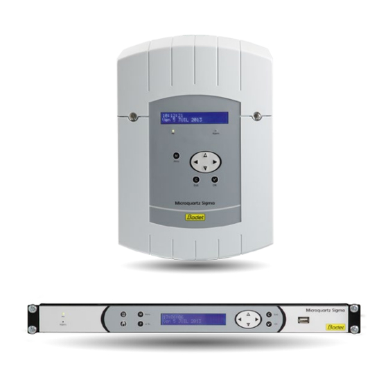
III - Identification - Sigma C USB connector LCD screen Alarm indicator light (red LED) Keypad (see page 15) Mains indicator light (green LED) 3.1 Wall Sigma C 3.2 Rack 19’’ Sigma C... -
Page 9: Iv - Installation
IV - Installation 4.1 Mechanical installation Choose a room with low temperature variations away from any source of electrical interference (contactors, motors, etc.). 4.1.1 Wall mounted version 1/ Loosen the 2 screws on the front. 2/ Remove the top cover: slide upward. 3/ Remove the cover bottom: Press the 2 clips (N) and slide upward. -
Page 10: Electrical Connections
4.2 Electrical connections 4.2.1 Wall mounted version Connect the cables to the corresponding terminal strips as shown in the figure below. See the limit characteristics of these circuits on page 40 110- 230VAC Attach the wires to each other, near the terminal strips. -
Page 11: Connecting A Melodys
4.2.3 Connecting a Melodys : Power supply Power supply Power supply depending on depending on the depending on the the model (24V or 240V)) model (24V or 240V) model (24V or 240V) Terminal of the Terminal of the Terminal of the Melodys Melodys Melodys... -
Page 12: V - Examples Of Setting
V - Examples of setting 5.1 Setting a DHF time distribution 1/ The DHF transmitter must be connected (see page 11). 03 : INIT ú 2/ Turn on the power to the master clock. 125mW canal:2 3/ Enter the technician menu (see page 26). 4/ Enter the “time output”... -
Page 13: Install An Option Board
2/ Install the option board in the slot, fix it with the screws provided and put the label in front of it. 3/ Connect the output or input lines of this board. 4/ Close the SIGMA C and switch it on. please note: in the “Time outputs” technician menu, “DEL” mode is used only to uninstall an option board from the master clock. -
Page 14: Key Functions
VI - Operating master clock 6.1 Key functions Keys Functions Calendar key. Test key. Menu key. Program key. Correction key. Validation key. Navigation keys. Please note: the exit from the menus is automatic if a key has not been pressed for one minute in the customer menu or for 5 minutes in the technician menu. -
Page 15: Synoptic Diagram Of The Programming
Synoptic diagram of the programming Modification of the programming for holidays and special days press 5sec +Technician code Choice of Load/save ... -
Page 16: Vii - Main Menu Programming
VII - Main menu programming 7.1 Standby state In normal operation the master clock displays the time and date : is the radio signal indicator, which flashes if reception is 10:54:32 poor. Mon 08 SEP 2014 If a bank holiday, a special day or a holiday period has 10:54:32 BANK DAY ... -
Page 17: Add Dhf Receivers
To load a Program in the master clock : 1/ Validate the option with the key. Restore: Nest01.02 ú The master clock will search for the files available on the Confirm ok exit C key (.sig extension). 2/ Select the file to be loaded using the keys. -
Page 18: Access Code
7.2.4 Access code To enter or remove the master clock access code : 1/ Validate the option with the key. Access code The following screen is displayed : Time and date õ 2/ Choose the option you require and validate it with the key. -
Page 19: Dynamic Reception
The languages available are : FRENCH, ENGLISH, Language:ENGLISH ú SPANISH, GERMAN, DUTCH, PORTUGUESE, NORWEGIAN and DANISH. 7.2.8 Version To view the version of the master clock, validate the option Version with the key. õ The following screen is displayed : SIGMA C Version V1.1E05 31/03/2015 ok... -
Page 20: Viii - Programming The Circuits
VIII - Programming the circuits 8.1 Prerequisite before programming circuits The programming and set up of Harmonys sounders on the computer network is done on the software. Please refer to the manual (ref: 607752). Programming circuits for Melodys and relay (physical or DHF). The different levels of the programming of these two modes are described below. -
Page 21: Viewing The Circuits
8.3 Viewing the circuits 1/ Select the number of the circuit you wish to view with the key. 2/ Select DISPLAY mode with the keys. 3/ Validate with the key Cir.01:08:02:00 03s The display of the parameters is fixed and the step MTWTFS- Weekly 01/12 ú... -
Page 22: Add A Program Step
5/ Enter the status of the circuit for this program step, choosing from ON, OFF, 01s (length in seconds which can be set using the keys) and DEL (DEL mode is used to delete the selected step), and then validate with the key. -
Page 23: Delete A Program Step
8.4.2 Delete a program step Circuit 01: PROG ú 1/ Select the number of the circuit you wish to delete a Circuit light program step using the key. Cir.1:08:00:00 06s ú 2/ Select the PROG mode with the MTWTFS- Weekly 03/05 validate with the key. -
Page 24: Ix - Manual Testing Of Circuits
IX - Manual testing of circuits While the status of a relay is displayed, it is possible to test it. 1/ Select the circuit you wish to test with the key. Circuit 12: START ú Access control If the circuit is a relay circuit: Cir.12: START TEST ú... -
Page 25: X - Programming In Holidays And Special Day Mode
X - Programming in Holidays and Special Day mode 10.1 Prerequisite before programming in holidays and sepcial day The programming and set up of Harmonys sounders on the computer network is done on the software. Please refer to the manual (ref: 607752). Programming circuits for Melodys and relay (physical or DHF). -
Page 26: Xi - Technician Menu Programming
XI - Technician menu programming The technician menu is accessible via an access code sent to the approved persons. Press one of the navigation keys for a few seconds. Enter TECHNICIAN code A code is then requested. **** The technician code is a fixed code, You then have access to the technician menu, Validate the required option with the key, or access the following options with the key. -
Page 27: Time Synchronisation Menu
11.1 Time synchronisation menu To configure the time synchronisation of the master clock, validate the option in the technician menu with the key. Time synchro The following screen is displayed : Time outputs õ Select the time synchronisation mode from the following options: Synchro:EXTERNAL ú... -
Page 28: Programmable Time Changeover
11.1.1 Programmable time changeover This menu can be used to program the summer/winter time changeover dates. It allows you to define the start of the winter period and then the start of the Prog. time change:Yes ú summer period. To program the summer/winter time changeovers, validate with the key. -
Page 29: Time Output Management Menu
11.2 Time output management menu Programming by PC software allows the time zone differential of each output to be set with respect to the local time. This menu can be used to view all the time outputs, modify their status (Start/Stop) and configure the DHF distribution in Init mode. -
Page 30: Ip Configuration Menu
=YES, then it is the network’s DHCP server which gives the product its IP parameters. If you wish to give the Sigma C a fixed address, validate this option (set to No) with the key. The following screen is displayed: IP Address : ú... -
Page 31: Relay Setting Menu
11.4 Relay setting menu This menu can be used to assign the relays (D1D2 and alarm). Relay setting To go to the master clock relay assignment menu, validate RHF Circuit õ the option in the technician menu with the key. The following screen is displayed : Rel. -
Page 32: Function Setting Menu
It can also be used to activate the backlight of the display screen. To go to the Sigma C function setting menu, validate the Function setting option in the technician menu with the... -
Page 33: Delete All Programming" Menu
11.8 CPU software download menu This menu allows you to update the program code in Flash. In the www.bodet-time.com/en/support.html, click on “Downloads”. Download the latest version of the programs on your USB flash drive. Update syst. soft ok To go to this master clock menu, validate the option in the Factory config. -
Page 34: Factory Setting Restoration Menu
11.9 Factory setting restoration menu This menu can be used to reinstall the initial factory setting. To go to this master clock menu, validate the option in the Factory config. technician menu with the key. õ The following screen is displayed : Restore config : No ú... -
Page 35: Xiii - Alarm Messages
XIII - Alarm messages By default, the alarm configuration is : - Activated: if an alarm is present, a message is displayed on the readout, - Alarm relay: relay 3 is activated if an alarm is triggered. - E-mail: the Sigma sends an e-mail (see messaging programming in the PC software), - SNMP: the SNMP server will receive a message (trap). - Page 36 Alarm message Meaning The user code has been entered three times incorrectly; the user code keyboard is blocked for 10 minutes. fail. The technician code has been entered three times incorrectly; the tech.code keyboard is blocked for 10 minutes. fail. The lithium battery used to save configuration data is defective;...
-
Page 37: Xiv - Options
XIV - Options The master clock can be fitted with option boards to extend its capacities. The option boards are installed “cold” and are automatically recognised when the master clock is switched on. The option boards are programmed with the software on PC. Caution: each Sound module counts for one extension card of the master clock (Max. - Page 38 14.2 Relay option board Circuit C1 Circuit C2 Circuit C3 This option board does not require any software programming. It allows 3 relays to be added. See the technician menu (circuit setting programming) on page 26. Please note: in the time output management menu of the technician menu, “DEL” mode is used only to uninstall the option board from the master clock.
-
Page 39: Three Inputs Option Card
14.3 Three inputs option card Input A Input B Input C This card allows the addition of 3 external inputs. 1/ Connect the lines carrying the external information to the inputs A, B and C. The parameter setting is accomplished with the PC software. See paragraph “USB transfer”... -
Page 40: Xv - Technical Characteristics
XV - Technical characteristics Designation Characteristics Permanent backup of all parameters in case of mains failure. Automatic Backup resetting of receiver clocks to correct time after mains restoration. Time base Quartz, accuracy 0.1 seconds per day between 20 and 25°. Capacity 500 program steps per circuit. -
Page 41: Xvi - What To Do If ...? Check That
There is drift of the time base. 1) Refer to the section on setting the time base drift. There is considerable drift (> 1) Send the equipment back to the BODET maintenance 0.5 seconds per day) of the department. time base. -
Page 42: Appendix I : Ntp Programming
Appendix I : NTP programming IP function programming The programming is carried out in 2 steps. 1 – Program the IP output (parameters supplied by the network administrator) from the technician menu of the master clock (see page 26). 2 – Software configuration. Start the PC software and then load the USB backup of your master clock. -
Page 43: Ip Network Configuration And Protocols Supported
The master clock is the NTP server In Configuration menu, select Time outputs and select NTP server. In NTP server mode, the master clock sends the time to the selected IP addresses with the selected mode of transmission. The clients will be in Broadcast or Multicast mode. For unicast client, you will have to enter the IP address of the master clock in the configuration parameters of the client. -
Page 44: Appendix Ii : Quick Start Guide
To program several holiday periods, use the PC software provided with the master clock. Access the user menu by pressing the key, to refer to the full record. © 2017 BODET SA. All rights reserved.
Need help?
Do you have a question about the Sigma C and is the answer not in the manual?
Questions and answers