Sign In
Upload
Download
Table of Contents
Contents
Add to my manuals
Delete from my manuals
Share
URL of this page:
HTML Link:
Bookmark this page
Add
Manual will be automatically added to "My Manuals"
Print this page
×
Bookmark added
×
Added to my manuals
Manuals
Brands
Extraflame Manuals
Stove
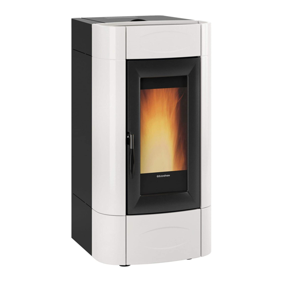
Isidora IDRO H16
User manual
Extraflame Isidora IDRO H16 User Manual
Hide thumbs
1
2
Table Of Contents
3
4
5
6
7
8
9
10
11
12
13
14
15
16
17
18
19
20
21
22
23
24
25
26
27
28
29
30
31
32
33
34
35
36
37
38
39
40
page
of
40
Go
/
40
Contents
Table of Contents
Bookmarks
Table of Contents
Table of Contents
English
Warnings
Safety
Routine Maintenance
Installation
Minimum Distances
Preparations for Maintenance
Hydraulic System
Installation and Safety Devices
Anti-Condensation Device (Mandatory)
Details Isidora H16 - H20
Features
Checks and Measures for Commissioning
The PELLET LOAD MOTOR DOES NOT FUNCTION
BULB Thermostats - RESET
Stove Positioning
Note for Correct Operation
Resetting
Fuse
Pellets and Feeding
Pellet Hopper - Pressurised Closure
Remote Control
Remote Control Icons
INSERTING the BATTERIES
ADVICE and PRECAUTIONS for the USE of the REMOTE CONTROL
Touch Screen Display
OPENING the DISPLAY
CLOSING the DISPLAY
Control Board
ICON Key
General Menu
GENERAL Warnings
First Ignition Settings
MAINS Power Frequency 50/ 60Hz
Date-Time
Language
Degrees
Operation and Logic
Stand-By - Additional Thermostat
Additional Thermostat Functioning with STAND-BY Active
ADDITIONAL Thermostat OPERATION with STAND-BY DEACTIVATED
ADDITIONAL Thermostat INSTALLATION
Ventilation
Easy Setup
Chrono
ENABLING/DISABLING the Chrono
Settings
Display
Stand - by
First Load
Outlet Air
Cleaning
Wi-Fi
Reset
Aux
Optional Additional Data Sheet
Cleaning and Maintenance
Maintenance
Periodic Cleaning under User's Responsibility
Routine Maintenance Performed by Qualified Technicians
Shut-Down (END of SEASON)
Displays
Alarms
Guarantee Terms
Disposal
Advertisement
Quick Links
Download this manual
THERMO PRODUCTS USER MANUAL
UK
isidora idro h16 - h20
MADE
IN
ITALY
design & production
004280106 - rev 000
Table of
Contents
Previous
Page
Next
Page
1
2
3
4
5
Advertisement
Table of Contents
Need help?
Do you have a question about the Isidora IDRO H16 and is the answer not in the manual?
Ask a question
Questions and answers
Related Manuals for Extraflame Isidora IDRO H16
Stove Extraflame HP15 Manual
Automatic loading pellet storage tank (68 pages)
Stove Extraflame RAFFAELLA IDRO H15 User Manual
Thermo products user manual (36 pages)
Stove Extraflame RAFFAELLA IDRO H18 User Manual
Thermo products user manual (36 pages)
Stove Extraflame Isidora IDRO H20 User Manual
(40 pages)
Stove Extraflame MARINA IDRO H11 User Manual
(40 pages)
Stove Extraflame Comfort Idro User Manual
(20 pages)
Stove Extraflame DUCHESSA IDRO Manual
(8 pages)
Stove Extraflame EcoLogica Idro Use And Maintenance Manual
(52 pages)
Stove Extraflame LUCREZIA IDRO Instruction Manual
Pellet stoves (48 pages)
Stove Extraflame VIRNA IDRO User Manual
(40 pages)
Stove Extraflame FIANDRA IDRO EVO User Manual
(40 pages)
Stove Extraflame LUISELLA User Manual
(37 pages)
Stove Extraflame MIETTA EVO User Manual
(40 pages)
Stove Extraflame Lucrezia User Manual
(40 pages)
Stove Extraflame DAHIANA User Manual
(40 pages)
Stove Extraflame ViViana User Manual
Stove and pellet inserts (28 pages)
This manual is also suitable for:
Isidora idro h20
001283900
001283901
001283800
001283801
001283802
Table of Contents
Print
Rename the bookmark
Delete bookmark?
Delete from my manuals?
Login
Sign In
OR
Sign in with Facebook
Sign in with Google
Upload manual
Upload from disk
Upload from URL


Need help?
Do you have a question about the Isidora IDRO H16 and is the answer not in the manual?
Questions and answers