Table of Contents
Advertisement
Quick Links
Wingspan:
39.7 in (1000mm)
Overall Length:
44.8 in (1130mm)
Wing Area:
548.7 sq. in. (35.4 sq. dm.)
Flying Weight:
37.0 oz (1050 g)
Wing Loading
30.0g /sq.dm
Motor Size:
3536-KV900
Radio:
4+ channel radio system (Required)
Servos:
(4*9g) servos
CG (center of gravity): 3-3/4 to 4 in (95-100mm) back
from the leading edge of the top wing
Prop Size:
11x7 electric propeller
Speed Control :
40-amp brushless
Recommended Battery: 11.1V(3S) 2200 mAh LiPo (Required)
Instruction
Manual
Advertisement
Table of Contents

Related Manuals for Hobby King Arcus F3A


Summary of Contents for Hobby King Arcus F3A
-
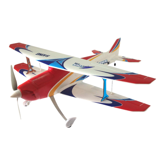
Page 1: Instruction Manual
Instruction Manual Wingspan: 39.7 in (1000mm) Overall Length: 44.8 in (1130mm) Wing Area: 548.7 sq. in. (35.4 sq. dm.) Flying Weight: 37.0 oz (1050 g) Wing Loading 30.0g /sq.dm Motor Size: 3536-KV900 Radio: 4+ channel radio system (Required) Servos: (4*9g) servos CG (center of gravity): 3-3/4 to 4 in (95-100mm) back from the leading edge of the top wing Prop Size:... - Page 2 TABLE OF CONTENTS IMPORTANT!!! SAFETY PRECAUTIONS ......1 Two of the most important things you can do to preserve the ADDITIONAL ITEMS REQUIRED .
-
Page 3: Additional Items Required
ADDITIONAL ITEMS REQUIRED The following items are required for assembling the Arcus 52779 Tail wheel assembly ARF: Swivel ball link plier 52780 Linkage #2Phillips screw driver 52781 Screw set 52782 Sticker ORDERING REPLACEMENT PARTS 52783 Motor shaft Replacement parts for the HOBBYKING Arcus 52784 Out-Runner brushless are available using the part numbers in the... -
Page 4: Charge The Battery Packs
CHARGE THE BATTERY PACKS ASSEMBLE THE MODEL Before you begin assembling your Hobbyking Arcus, The general maintenance thoroughly read the instruction manual included with the Note: Before using CA or Epoxy glue, please test fit the battery charger. Also familiarize yourself with the following parts before applying the glue to make sure the parts fit lithium polymer battery cautions. - Page 5 Install the swivel ball on the rudder horn and glue Before installation of the motor and propeller, the horn to the rudder using foam safe glue connect the ESC to the motor Glue in the magnets for the cowling and battery Attach the sheet metal to the battery hatch and put the hatch into place hatch...
- Page 6 Glue the servo mounting brackets into place using Install the control surface horns to the lower wings thick CA. Add a drop of CA to the screw mounting holes using Epoxy and mount the aileron servos in the servo and let cure to strengthen the plywood before mounting bays using Epoxy the servos into place Install the lower wing mounting nose using Epoxy...
- Page 7 The horizontal stabilizer and the elevator assembly 1. Insert the CF rod into the stabilizer joiner fully and a small drip of CA is needed to fix the rod firmly in it. The main landing gear assembly Put together the wheel pants clips using CA. Secure the gear axles with the nylon nuts provided and fit the wheels into the wheel pants and the wheel pants to the clips.
-
Page 8: The General Assembly
The general assembly Install the landing gears When installing the landing gear, make sure to Snap the left stabilizer half into place and make sure insert the steering arm into the socket on the bottom that the elevator connector is properly in place on both of the rudder. - Page 9 To install the lower wing, key the mounting nose into the slot at the front of the wing mounting bay on the fuselage. Pull the servo cables through the hole in the fuselage into the receiver bay, then fully attach the wing to the fuselage, making sure the cables are not torn and/or prevent the wing from properly sitting in the wing mounting bay.
-
Page 10: Prepare For Flight
The receiver and the battery department Connect the servo cables and the ESC cable to the Aileron: Bank Left receiver and secure the receiver with the Velcro tape. Slide the battery into the battery bay as shown in the picture Aileron: Bank Right Rudder: Yaw Left PREPARE FOR FLIGHT... -
Page 11: Operate The Motor
Operate the motor 1. Important ESC notification, make sure the throttle stick and the trim are in the lower position before connect the battery to the ESC to avoid the motor starts inadvertently. 2. The motor and the ESC comes pre-connected, please make sure the motor rotates in the right direction. -
Page 12: Install The Propeller
Install the propeller Check the C.G. (Center of Gravity) Note: The C.G. (Center of Gravity)is the location on !!!Caution: Disconnect the battery from the ESC the wings, measured back from the most leading edge before installing the propeller. Before testing the of the top wings on both sides of the fuselage, where propeller, make sure the tail of the plane is firmly gripped the model balances. -
Page 13: Find A Suitable Flying Site
Find a suitable flying site Find a flying site clear of buildings, trees, power lines And make sure the spinner and the propeller are firmly and other obstructions. Until you know how much area in place before every flight. will be required and have mastered flying your plane in confined spaces, choose a site which is at least the Place the model on your “runway”... -
Page 14: Troubleshooting
TROUBLESHOOTING Problem Possible Cause Solution Aircraft will not - Lower throttle stick and throttle - ESC is not armed. respond to the trim to lowest settings. - Throttle channel is reversed. throttle but responds - Reverse throttle channel on to other controls. transmitter. - Page 15 MADE IN CHINA...
Need help?
Do you have a question about the Arcus F3A and is the answer not in the manual?
Questions and answers