
Related Manuals for Gfp 563TH


Summary of Contents for Gfp 563TH
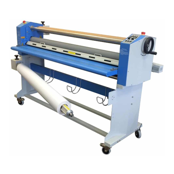
- Page 1 OPERATING MANUAL Gfp 563TH Please read this manual carefully before operating! Unpacking, assembly, and operating videos are available at www.gfpsmoothstart.com...
- Page 2 Table of Contents Contents Page Introduction …………………………………………………… Important Safety Instructions………………………………….. Installation Safeguards. ……………………………………….. General Safeguards……………………………………………. Operating Conditions …………………………………………. System Components ………………………………………….. Control Panel …………………………………………………. Packing List ………………………………………………… .. Installation A. Remove crate top…….…………………………………. 10 B. Remove packing materials……………………………... C. Assemble machine stand.….……………………………. 11 D.
-
Page 3: Introduction
1. Introduction Thank you for choosing the Gfp 563TH laminator. It has been designed and manufactured to provide years of continuous service. Please read this manual thoroughly before operating. Please inspect the box and the laminator for shipping damage. Damage should be brought to the attention... - Page 4 • Contact an electrician should the attachment plug provided with the laminator not match the receptacles at your location Ensure that the voltages of the power supply you are using match the rated working • voltages before operations. Do not use incorrect power supply Do not use damaged wires or sockets.
-
Page 5: General Safeguards
4. General Safeguards • Keep hands, long hair, loose clothing, and articles such as neckties away from rollers to avoid entanglement and entrapment. The rollers have pinch points that can trap body parts or clothing and cause serious injury • Do not use the machines for purposes other than lamination and mounting, otherwise damages to the machine or accidents may occur •... -
Page 6: Operating Conditions
5. Operating Conditions • Place machine on level surface • Environment requirements: • Ambient temperature: 50⁰ F - 104⁰ F • Humidity:30%—80%;ideal humidity:55% • Due to the static on film rolls, you should try to keep the environment clean. • Provide enough space around machine to ensure the safe and effective operation. minimum area covered is 8 ft. -
Page 7: System Components
6. System Components Linkage Axle 11. Power cord 21. Exit table 2. Emergency Stop switch 12. Main power switch 22. Bottom nip roller 3. Left cabinet 13 Roller gap hand-wheel 23. Support crossbar 4. Assembly cover 14. Control panel 24. Cross member 5. -
Page 8: Control Panel
7. Control Panel 1. Cold laminating indicator 6. Hot / Cold heater switch 2. Hot laminating indicator 7. Forward / Reverse switch 3. Ready light indicator 8. Continuous/ foot pedal operation 4. Temperature display screen 9. Temperature adjustment 5. Speed adjustment Note: 1. -
Page 9: Packing List
8. Packing List Remove all parts from shipping create and boxes. Inspect parts and the machine carefully. Any missing parts should be reported to the shipper upon receipt of shipment. Main Machine Crate Stand Box Part Quantity Part Quantity Main Machine Cross beams Swing out shaft assembly Middle beam... -
Page 10: B. Remove Packing Materials
9. Installation 9A. Remove crate top 1. Remove screws around the base of the crate including corner supports 2. Lift crate straight up and off the skid Crate 9B. Remove packing materials 3. Remove plastic cover and accessory box. 4. Raise the In-feed table and lock in place 5. -
Page 11: C. Assemble Machine Stand
1. Accessory box and manual 2. Top rewind mandrel 3. Top supply mandrel 4. Bottom supply shaft assembly 5. Shipping skid 9C. Assemble machine stand 1. Remove stand from shipping box 2. Bolt cross members to stand side frame 3. Larger cross member goes in the center and takes the shorter bolts 4. -
Page 12: D. Attach Lower Supply Shaft
9D. Attach lower supply shaft assembly 1. Bolt bottom supply shaft assembly to the stand with 6 bolts 2. Bolt cover to supply shaft assembly 3. Bolt machine alignment brackets to the outside of machine stand Machine alignment brackets Tension knob Cover Bottom supply shaft... -
Page 13: F. Align Machine To Stand
9F. Align machine to stand 1. Screw one Alignment bolt through the alignment bracket into machine frame on the outside of each stand leg. Note: You may need to slide machine to align holes in machine frame with machine stand Alignment bolt 2. -
Page 14: Loading Film
11. Loading Film 1. Rotate the locking outer sleeve to the open position, aligned with the inner sleeve 2. Swing the supply shaft out to load position and slide the film roll onto the shaft Note: If using Liner-in film, the web should come off the bottom of the roll, for Liner- out film, the web should come off the top of the roll (see treading diagram in section #12) 3. -
Page 15: Threading Film
12. Threading Film 1. Pull the top film web under the rewind shaft, making sure there is proper resistance. The resistance can be adjusted with the adjusting knob on top of the supply shaft assembly 2. Turn the pressure-adjusting hand-wheel to lift up the top rubber roller. 3. -
Page 16: Operation
13. Operation 1. Plug power cord into a proper receptacle Connect the attachment plug provided with the laminator to a suitably grounded • outlet only. This machine must have reliable earth wire to ensure the safety of the machine during operations •... -
Page 17: Brake Tension Adjustment
15. Brake Tension Adjustment 1. Adjust brake tension by turning the Tension adjustment knobs on top of each supply shaft assembly 2. Apply only enough brake tension to remove wrinkles from the vinyl web before it enters the nip rollers 3. -
Page 18: Inserting Rewind Shafts
17. Inserting rewind shafts 1. Slide a cardboard core onto the rewind shaft 2. Rotate the locking outer sleeves on both sides of the machine to the open position 3. Align the arrow and shaft tongue with the slot in support bracket on one side 4. -
Page 19: Optional Rewind
20. Optional Rewind One or two sets of Rewind devices can be added to the machine as required. One can be fixed in the rear of the machine for rewinding finished material, and another on the front of the stand to take up backing paper from the bottom roll of cold film when doing double- side cold lamination. -
Page 20: Roller Gap Adjustment
21. Roller Gap Adjustment 1. Check for uneven roller gap a. Place a sheet of paper between the rollers the full width of the laminator b. Turn the pressure-adjusting hand-wheel to lower the upper rubber roller so the two rollers just touch c. -
Page 21: Troubleshooting
22. Troubleshooting Problems Causes Solutions 1. No power supply 1. Plug in power cord 2. Main power switch is OFF 2. Place power switch to ON Machine does not turn on 3. Circuit breaker has tripped 3. Reset circuit breaker 4. -
Page 22: Specifications
23. Specifications Description 563TH Laminating Width 63” Roller Diameter 4.5” Roller Gap 1” Max Temperature 122⁰ F Film core size 3” Laminating Speed 0-20 Ft/min Pressure Adjustment Hand wheel Heat Method Metal alloy tube Power Supply 110 v 12 Amp... -
Page 23: Warranty
Gfp’s option, replaced without charge. This warranty is extended only to the original purchaser. This warranty is the only warranty made by Gfp and cannot be modified or amended. Gfp’s sole and exclusive liability and the customer’s sole and exclusive remedy under this warranty shall be, at Gfp’s option, to repair or replace any such defective part or product.
Need help?
Do you have a question about the 563TH and is the answer not in the manual?
Questions and answers