Table of Contents
Advertisement
This Manual Must Be Read Before Operating The Equipment
Owner / Operator's Manual
Warren, Michigan 48089
800-725-8377
800-
800-
725-8377
725-8377
© Trynex International 2008
Spreaders for Snow & Ice Control
L1184
Protected by the following patents, #6,089,478, #6,088,865, #Des.425,915
and other pending U.S. and foreign patent applications.
Rev. 07
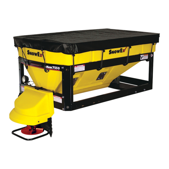
FOR MODEL
7500
CUSTOMER COPY
4 — 1
Advertisement
Table of Contents

Subscribe to Our Youtube Channel
Related Manuals for SnowEx 7500


Summary of Contents for SnowEx 7500
- Page 1 This Manual Must Be Read Before Operating The Equipment Owner / Operator’s Manual Spreaders for Snow & Ice Control FOR MODEL 7500 CUSTOMER COPY Protected by the following patents, #6,089,478, #6,088,865, #Des.425,915 Warren, Michigan 48089 and other pending U.S. and foreign patent applications.
-
Page 2: Table Of Contents
Table of Contents Introduction ................... 3 General Information and Registration . -
Page 3: Introduction
Introduction This manual has been designed for your help. It will assist you and instruct you on the proper set-up, installation and use of this spreader. Refer to the table of contents for an outline of this manual. We require that you read and understand the contents of this manual completely (especially all safety information) before attempting any procedure contained herein. -
Page 4: General Information
RELIABILITY: High impact linear low density polyethelyne hopper, state-of-the-art electronic dual variable speed control, custom engineered powder coated frame, maximum torque 12 volt motor coupled to a custom engineered transmission found only on SnowEx products. VERSATILITY: Multi-use capabilities allows spreading of a variety of materials for snow and ice control. - Page 5 The unit, or any part of it should be altered without prior written permission from the manufacturer. Never use 7500 with foreign debris in the spreader. These units are designed to handle clean, free-flowing material. Note: Can not spread water softner salt.
- Page 6 Safety (continued) Always inspect pins and latches whenever attaching or detaching spreader, and before traveling. Never leave material in hopper for long periods of time. Be aware that all ice melters are hygroscopic and will attract atmospheric moisture and harden up. Remember, most accidents are preventable and caused by human error.
- Page 7 Safety and Warning Labels SERIAL NUMBER ON REVERSE SIDE UNDER COVER D 6546 D 6859 D 6545 D 6544 D 6335 D 6548 Rev. 07 © Trynex International 2008 L1184 4 — 7...
- Page 8 7550 Component Assembly Views Spinner Drive Auger Drive Assembly Assembly Electrical System Assembly Hopper Frame Assembly Assembly Rev. 07 4 — 8 L184 © Trynex International 2008...
- Page 9 7500 Side and Bottom Views Rev. 07 © Trynex International 2008 L1184 4 — 9...
- Page 10 7500 Auger Drive Assembly Parts Breakdown Rev. 07 4 — 10 L1184 © Trynex International 2008...
- Page 11 7500 Auger Drive Assembly Parts Breakdown . y t D5514 Rear Spinner Drive Mount D5520 48” Auger Weldment D5522 Auger Motor D6826 80:1 Auger Transmission D5527 Auger Bearing D5532 Auger Coupling Hub 1” D5533 Auger Coupling Spyder 1” D6873 3/16” Keyway Stock...
- Page 12 7500 Spinner Drive Assembly Parts Breakdown Rev. 07 4 — 12 L1184 © Trynex International 2008...
- Page 13 7500 Spinner Drive Assembly Parts Breakdown . y t D5502 Spinner Hood D5518 Spinner Enclosure Plastic Chute D6832 Plastic Deflector D6833 Spinner Tube Guard D6820 D4134 Hairpin Clip Spinner Assembly D6516 Spinner Transmission D6107 D6162 Power Cord Enclosure Cover D6819...
- Page 14 7500 Hopper Assembly Parts Breakdown Rev. 07 4 — 14 L1184 © Trynex International 2008...
- Page 15 7500 Hopper Assembly Parts Breakdown . y t 5500 7500 Hopper 5512 Top Screen Inverted-V Assembly D 5510 D 5508 Inverted-V Backing Plates D 4121 3/8”-16 x 1” Hex Bolt D 5517 Salt Discharge Baffle D 6515 Heavy Duty Vibrator 1/4”...
- Page 16 7500 Frame Assembly Parts Breakdown Rev. 07 4 — 16 L1184 © Trynex International 2008...
- Page 17 7500 Frame Assembly Parts Breakdown Description Qty. D 5505 7500 Frame Weldment D 5506 Rear Apron D 5504 Auger Motor/Transmission Support D 5507 Upper/Lower Front Facia 1/2-13 x 1” Serrated Hex Head Bolt D 6528 Frame Assembly Rev. 07 © Trynex International 2008 L1184 4 —...
-
Page 18: Wiring Instructions
It is not recommended to attach to fuel or brake lines for obvious reasons. Do not route close to exhaust system or engine, even though Snowex uses high temperature wiring, it still could melt under extreme heat and short the spreader electrical system, as well as the vehicle electrical system. - Page 19 7500 Electrical System Parts Breakdown Description . y t Spreader Speed Control D 5525 D 6341 Control Power Harness D 6322 Vehicle Harness Spreader Harness D 5524 Vehicle Harness Dust Cap D 6343 Spreader Spinner Plug Dust Cap D 6118 Rev.
- Page 20 D5525 Control 20 Amp Circuit Breaker Black OUTPUT Negative (–) Vibrator INPUT Black Negative (–) Spinner Vibrator Red Positive (+) Red Positive (+) Auger Red Positive (+) Spinner Black Negative (–) Positive (+) Auger Black Negative (–) D6341 Control Power Cable Negative Black (–) to battery Ring Terminal...
- Page 21 D5524 Spreader Power Harness Circuit Diagram AUGER Green Negative (–) AUGER Red Positive (+) SPINNER VIBRATOR White Positive (+) Green Black Negative (–) Negative (–) Positive (+) VIBRATOR SPINNER White Positive (+) Black Negative (–) MAIN POWER PLUG AUGER POWER SPREADER CONNECTION White...
- Page 22 D6322 Vehicle Harness CONTROL OUTPUT PLUG VIBRATOR BUMPER SPINNER/AUGER CIRCUIT PLUG Anderson CIRCUIT Anderson OUTPUT Block Block (2) Pos (4) Pos VIBRATOR Black Negative (–) SPINNER OUTPUT Red Positive (+) VIBRATOR White Positive (+) Positive (+) SPINNER OUTPUT Black Black Negative (–) Negative (–) SPINNER AUGER OUTPUT...
- Page 23 7500 Mounting System SMK-175 Mounting Instructions Through floor/bed mounting bolts. Figure 1 Figure 2: Frame Mounting Bolts (INCLUDED WITH SPREADER) Rear Stop LT & RT i r c i t p . y t D 4116 1/2”-13 x1-1/2” Hex Bolt Flat Washer "...
- Page 24 Step 7: Install and tighten all (4) bolts. Step 8: Install ratchet straps (see 7500 Mounting System: Strapping Techniques). It is very important for everyone’s safety this strapping method be used as the standard mounting procedure. (Do not use ratchet straps exclusively.) Step 9: Connect the spreader power cord to vehicle main power plug mounted at rear of vehicle (see Electrical Installation).
- Page 25 XMT-275 Vee Pro Express Mount Kit Mounting Instructions NOTE: Pay special attention when drilling or clamping dissimilar metals to aluminum bodies. Galvanic corrosion can occur if not handled properly. Contact vehicle manufacturer for recommended attachment practices. IN BED EXPRESS MOUNT Step 1: Locate left and right side mounting rail Step 2: Locate item cross rails.
- Page 26 XMT-275 Express Mount Kit Parts Breakdown Use Bushings To Space frame out if required. . y t D 6590 Mounting Rail Left D 6589 Mounting Rail Right D 6591 Cross Rail 6595 Backing Plate D 6593 Stop Latch Lt Side D 6592 Stop Latch Rt Side D 6573...
- Page 27 FFK-020 Assembly Instructions Baffle Kit For 7500 Spreader Leave original baffle in place. Step 1. Mount item # 1 using two self drillers. Locate so that existing 7500 baffle is sealed off. Step 2. Fill spreader with material and check to see if leakage is still occuring.
-
Page 28: Operating The Spreader
Operating the Spreader (continued) D5517 DISCHARGE BAFFLE & INVERTED-V INSTRUCTIONS The 7550 uses a Inverted-v design over the auger area. This inverted-v (D5510) is used to reduce load to the auger drive train. It must not be removed unless servicing the unit. The 7550 uses a discharge baffle (D5517) to reduce material leakage D5510 It must not be removed unless servicing the unit. - Page 29 Spread ice melters with the storm to prevent unmanageable levels of ice. Calculate spread pattern when near vegetation. 7500 CONTROL OPERATION The Dual Variable Speed Control has dual finger-tip dials for maximum performance, digital system status with warning protection and built-in Vibrator Switch.
- Page 30 Operating the Spreader (continued) WARNING PROTECTION If audible beeping occurs, read display to identify problem. If display reads “OL” (overload) or “OH” (overheat). Shut controller down and carefully clear jammed auger. If display reads “E1“ this means there is a dead short in system. Do not use until problem is cor rected. If display reads “E 0”...
-
Page 31: Troubleshooting
Troubleshooting Whenever service is necessary, your local SnowEx Dealer knows your Spreader best. Take your Spreader to your local dealer for any maintenance or service needs on your unit. If this is not possible, the Troubleshooting Guide below may assist you in identifying the problem. - Page 32 Troubleshooting 7500 CONTROLLER TURNS ON DEFINITION: SWITCH OFF & ON SPREADER OL CODE JAMMED MATERIAL CLEAR JAM BEEP SHUTS OFF AMP DRAW FOR AUTO-REVERSE DOES NOT RUN DISPLAYS ERROR CODE TOO HIGH FUNCTION BAD MOTOR TEST 4 TO 20 AMP DRAW...
- Page 33 Troubleshooting 7500 MATERIAL CHECK BAFFLE 18" CORRECT MATERIAL ISSUE FREE FLOWS LENGTH SHOULD TOUCH CHECK BAFFLE MATERIAL ISSUE HOPPER ON 3 SIDES POSITION MATERIAL MATERIAL REMOVE MATERIAL ISSUE DOES NOT FLOW OBSTRUCTION OBSTRUCTION RUN 12 VOLT TO AUGER RUNS AUGER CIRCUIT ON...
-
Page 34: Spreader Maintenance
Spreader Maintenance WARNING – When servicing is necessary, perform it in a protected area. Do not use power tools in rain or snow because of danger of electrical shock or injury. Keep area well lighted. Use proper tools. Keep the area of service clean to help avoid accidents. WARNING –... -
Page 35: Torque Chart
Useful Formulas Determining Vehicle Payload Example: Material Type Coarse Salt – Dry Equipment installed when vehicle 6'/8' Vee Pro 7500 was weighed Front Gross Axle Weight Rating (RGAWR) Rear Vehicle Weight Rating 8600 (GVWR) (lb.) Gross Vehicle Weight (GVW) (lb.) (empty) –... -
Page 36: Blank
THIS PAGE INTENTIONALY LEFT BLANK Rev. 07 © Trynex International 2008 L1184 4 — 36... - Page 37 THIS PAGE INTENTIONALY LEFT BLANK Rev. 07 © Trynex International 2008 L1184 4 — 37...
-
Page 38: Warranty
Warranty Limited Warranty Warranty will be for a period of two years from the date of purchase against defects in material or workmanship under normal use and service, subject to limitations detailed below. Warranty period of one year begins on the date of purchase by the original retail user. The WARRANTY REGISTRATION CARD must be returned to the manufacturer for this warranty to become effective. - Page 39 Warranty Registration and Customer Survey To initiate the warranty on your new SnowEx spreader and assure prompt warranty service, please complete the following warranty registration and customer survey, sign and mail it back to the factory within 30 days of purchase.
- Page 40 W arm Up to with a F R E E F R E E Winter Hat! Simply Fill Out Your Warranty Registration and Return It to the Factory! From: Postage Required Post Office will not deliver without proper postage. 23455 REGENCY PARK DR. WARREN MI 48089-2667 Rev.
Need help?
Do you have a question about the 7500 and is the answer not in the manual?
Questions and answers