
Related Manuals for SnowEx VX-3200


Summary of Contents for SnowEx VX-3200
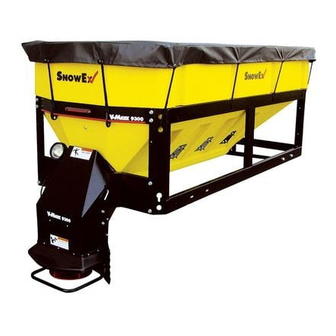
- Page 1 September 15, 2017 Lit. No. 70465, Rev. 02 V-Maxx™ G2 Hopper Spreader VX-3200 Owner's Manual Original Instructions CAUTION Read this document before operating or servicing spreader. A DIVISION OF DOUGLAS DYNAMICS, LLC...
-
Page 3: Table Of Contents
TABLE OF CONTENTS PREFACE ..............5 ON Mode ............17 Owner's Information ..........5 Error Mode ........... 17 SAFETY ..............6 Cab Control Codes ..........18 Safety Defi nitions ..........6 Setup Procedures ..........20 Warning/Caution Labels ........6 Calibrate Empty Hopper Setting (Cb and EH Codes) ........ - Page 4 Lit. No. 70465, Rev. 02 September 15, 2017...
-
Page 5: Preface
PREFACE This manual has been prepared to acquaint you with the safety information, operation, and maintenance of your new hopper spreader. Please read this manual carefully and follow all recommendations. This will help ensure profi table and trouble-free operation of your hopper spreader. -
Page 6: Safety
SAFETY SAFETY DEFINITIONS WARNING/CAUTION LABELS Please become familiar with the Warning and Caution WARNING labels on the spreader. Indicates a potentially hazardous situation that, if not avoided, could result in death or NOTE: If labels are missing or cannot be read, see serious personal injury. -
Page 7: Serial Number Label
Serial Number Label (inside frame) SERIAL NUMBER LABEL TrynEx International, LLC 531 Ajax Drive Madison Heights, MI 48071 Code Defi nition VX-3200 3.2 CU YD AUGER POLY HOPPER 2-Digit Year 2-Digit Month YYMMDDLLXXXXZZZZZ 2-Digit Day 2-Digit Location Code XXXX 4-Digit Sequential Number ZZZZZ 5–7-Digit Assembly Part Number... -
Page 8: Safety Precautions
SAFETY SAFETY PRECAUTIONS CAUTION • Do not operate a spreader in need of Improper installation and operation could cause maintenance. personal injury and/or equipment and property • Before operating the spreader, reassemble damage. Read and understand labels and this any parts or hardware removed for cleaning Owner's Manual before installing, operating, or or adjusting. -
Page 9: Personal Safety
SAFETY PERSONAL SAFETY VENTILATION • Remove ignition key and put the vehicle in park or WARNING in gear to prevent others from starting the vehicle Vehicle exhaust contains lethal fumes. during installation or service. Breathing these fumes, even in low •... -
Page 10: Torque Chart
SAFETY TORQUE CHART CAUTION Read instructions before assembling. Fasteners should be fi nger tight until instructed to tighten according to the Torque Chart. Use standard methods and practices when attaching spreader, including proper personal protective safety equipment. Recommended Fastener Torque Chart Inch Fasteners Grade 5 and Grade 8 Torque (ft-lb) Torque (ft-lb) -
Page 11: Loading
Do not exceed GVWR or GAWR as found on the driver-side cornerpost of vehicle. SPREADER SPECIFICATIONS Capacity Overall Empty Overall Hopper Struck Length Length Weight Width Height Model (in) (in) (lb) (in) (in) VX-3200 Lit. No. 70465, Rev. 02 September 15, 2017... -
Page 12: Load Volume
WARNING Hopper Model Overloading could result in an accident or damage. Do not exceed GVWR or GAWR VX-3200 (3.2 ratings as found on the driver-side door cornerpost of the vehicle. See Loading section to determine maximum volumes of spreading material. -
Page 13: Determining Vehicle Payload - Worksheet
LOADING Determining Vehicle Payload – Worksheet Example: Material Type Salt Equipment installed when VX-3200 vehicle was weighed Spreader Front Gross Axle Weight 5600 Rating [FGAWR] (lb) Rear Gross Axle Weight 9900 Rating [RGAWR] (lb) Gross Vehicle Weight 15500 Rating [GVWR] (lb) Gross Vehicle Weight [GVW], –... -
Page 14: Mounting The Spreader
MOUNTING THE SPREADER 4. Adjust the spreader position to align the holes in the INSTALL HOPPER IN VEHICLE BED hopper frame and front mounting brackets with the mounting holes in the vehicle bed. If mounting holes NOTE: Periodically throughout the snow and ice are not already drilled, refer to the Hopper Spreader control season, verify that mounting devices Installation Instructions for drilling instructions. -
Page 15: Installing & Removing The Spinner Assembly
INSTALLING & REMOVING THE SPINNER ASSEMBLY INSTALL SPINNER ASSEMBLY TO REMOVE SPINNER ASSEMBLY HOPPER 1. Disconnect the spinner motor plug. 1. Remove the 1/4" x 20" locking pin and hairpin 2. Remove the 1/2" x 20" locking pin. cotter. 3. Remove the spinner assembly from the spreader. 2. -
Page 16: Operating The Spreader - Cab Control
OPERATING THE SPREADER – CAB CONTROL If any button is pressed on the control, it will wake and WARNING check again for spreader connection. If no spreader Never operate equipment when under the is detected, it will act as previously described. If a infl... -
Page 17: Controlling Material Application
OPERATING THE SPREADER – CAB CONTROL CONTROLLING MATERIAL APPLICATION Ready Mode Vehicle ignition is set to ACC or ON; cab control is OFF. The material application settings can be adjusted Control has power. Spreader is detected. while spreader is ON or OFF. Settings are shown by the indicator lights around the control knobs. -
Page 18: Cab Control Codes
OPERATING THE SPREADER – CAB CONTROL CAB CONTROL CODES Setup Codes Code Defi nition Procedure Calibrate the Empty Hopper setting. With control in ON mode, press and hold the left control knob until the Cb code displays. Calibration cycle is automatic.* Clear calibration data for Empty Hopper Press the right control knob to clear all calibration data during the setting;... - Page 19 OPERATING THE SPREADER – CAB CONTROL CAB CONTROL CODES continued Error Codes – Spreader Operation Stopped Code Defi nition Possible Cause Suggested Solution Hopper overload – Drive system has high current. Inspect auger; clear material jam, or fi x auger as software trip.
-
Page 20: Setup Procedures
OPERATING THE SPREADER – CAB CONTROL SETUP PROCEDURES Adjust LED Brightness Level (LS and SL Codes) Calibrate Empty Hopper Setting The brightness setting of the cab control lights can be (Cb and EH Codes) adjusted from 1 to 16. The factory default setting is 8. Calibrating the empty hopper setting enables the cab 1. -
Page 21: Auto-Reverse (Ar) Feature
2. Continue to hold the BLAST button and turn the right-hand knob to control the material fl ow The V-Maxx™ VX-3200 uses an inverted V baffl e setting (range is 2–30). Turn the knob clockwise to design over the auger area. This baffl e is used to increase the fl... -
Page 22: Spreading Tips
OPERATING THE SPREADER SPREADING TIPS DUMP FUNCTION • Spread ice melters with the storm to prevent The dump function allows the operator to activate the unmanageable levels of ice. auger to empty the hopper after use or load material into a walk-behind spreader. •... -
Page 23: Removing & Storing The Spreader
REMOVING & STORING THE SPREADER REMOVE HOPPER FROM VEHICLE BED 4. Remove the mounting hardware from the frame mounting holes and the tie-downs straps from the frame corners. WARNING Never remove the spreader with material in the hopper. 1. Remove the spinner assembly from the hopper body and set it aside. -
Page 24: Maintenance
MAINTENANCE AFTER FIRST USE WARNING Tighten all mounting fasteners. Never remove the spreader with material in the hopper. AFTER EACH USE • Wash unit after each use to prevent material CAUTION build-up and corrosion. Disconnect electric power at spreader NOTE: Do not spray water directly on the auger electrical wiring harness connection and tag bearing and seals. -
Page 25: Electrical Components
ELECTRICAL COMPONENTS VEHICLE HARNESS DIAGRAM Cab Control 18 ga Red 4-Way Connector To Vehicle Switched Accessory Vehicle Control Harness To Vehicle CHMSL Signal (tap located in cab) Connectors 18 ga Shielded Twisted-Pair Cable 6 ga Red 100 A Fuse 4 ga Red 18 ga Black Vehicle 4 ga Black... -
Page 26: Electrical Control Box Schematic
ELECTRICAL COMPONENTS ELECTRICAL CONTROL BOX SCHEMATIC ACC Relay-Fuse Spreader Module Mounting Bracket SPIN FEED Auger Auger Switch Switch Accessory Work Light Switch To CHMSL To Auger Motor Spreader Harness Vibrator Assembly Harness ACC Power Block ACC Taps (cover removed) To Spinner Motor Lit. -
Page 27: Troubleshooting Guide
TROUBLESHOOTING GUIDE Please see your authorized dealer for service. The troubleshooting reference table below may guide you in diagnosing the issue. For a reference table of the cab control error codes, see the "Operating the Spreader – Cab Control" section of this manual. - Page 28 U.S. patents: 7,400,058; 7,737,576, and other patents pending. TrynEx International offers a limited warranty for all spreaders and accessories. See separately printed page for this important information. The following are registered ( ® ) or unregistered (™) trademarks of Douglas Dynamics, LLC: SnowEx , V-Maxx™. ® Printed in U.S.A.
Need help?
Do you have a question about the VX-3200 and is the answer not in the manual?
Questions and answers