Table of Contents
Advertisement
Quick Links
January 1, 2017
Lit. No. 75312, Rev. 00
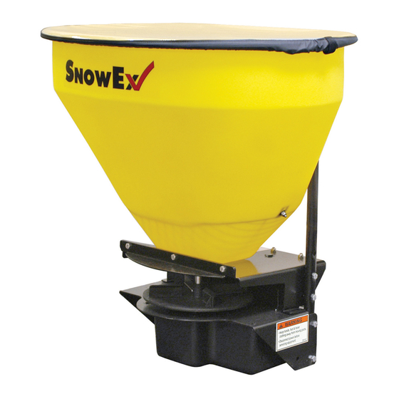
SP-100-1 & SP-125-1
Tailgate Spreader
Owner's Manual and Installation Instructions
Original Instructions
CAUTION
Read this manual before installing or
operating the spreader.
This manual is for SnowEx
SP-100-1 & SP-125-1 tailgate spreaders with
®
serial numbers beginning with 170109 and higher.
This document supersedes all editions with an earlier date.
Advertisement
Table of Contents


Need help?
Do you have a question about the SP-100-1 and is the answer not in the manual?
Questions and answers