Advertisement
Quick Links
This Manual Must Be Read Before Operating The Equipment
Owner / Operator s Manual
Spreaders for Snow & Ice Control
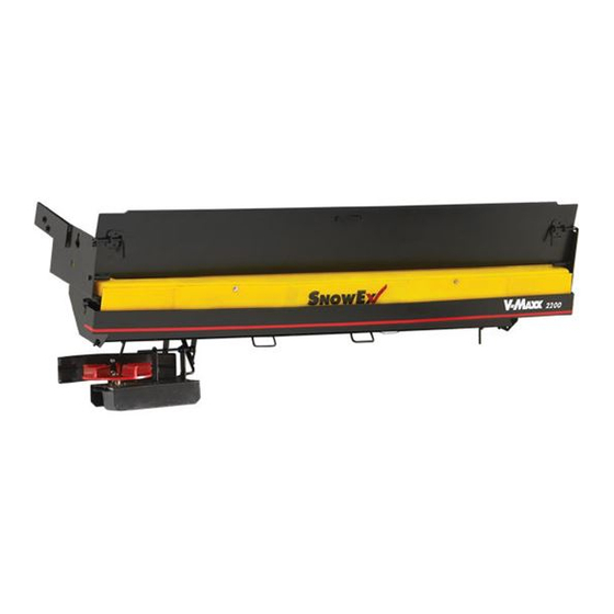
FOR MODEL
SP-2200
For use on vehicles with a GVW of 26,000 or higher.
CUSTOMER COPY
-
Protected by the following patents, #6,089,478, #6,088,865, #Des.425,915
and other pending U.S. and foreign patent applications.
1
Advertisement

Related Manuals for SnowEx SP-2200


Summary of Contents for SnowEx SP-2200
- Page 1 This Manual Must Be Read Before Operating The Equipment Owner / Operator s Manual Spreaders for Snow & Ice Control FOR MODEL SP-2200 For use on vehicles with a GVW of 26,000 or higher. CUSTOMER COPY Protected by the following patents, #6,089,478, #6,088,865, #Des.425,915...
- Page 2 ..................3 Have a question or need assistance? SnowEx Customer Service (800) 725-8377...
- Page 3 Introduction This manual has been designed for your help. It will assist you and instruct you on the proper set-up, installation and use of this spreader. Refer to the table of contents for an outline of this manual. We require that you read and understand the contents of this manual completely (especially all safety information) before attempting any procedure contained herein.
-
Page 4: General Information
Tryn x products. Here’s why... SIMPLICITY: Fewer moving parts manufactured of higher quality means minimal maintenance for your SnowEx spreader. RELIABILITY: High impact linear low density polyeth l ne hopper, state-of-the-art electronic dual variable speed control, custom engineered powder coated frame, maximum torque 12 olt motor coupled to a custom engineered transmission found only on SnowEx products. - Page 5 Safety WARNING SAFETY DEFINITIONS • Always make sure personnel are clear of areas of danger when using equipment. WARNING • Never attempt to lift a unit with material in it. Indicates a potentially hazardous situation • Always inspect unit for defects and that, if not avoided, could result in death or replace any broken, missing or worn parts serious personal injury.
- Page 6 Safety (continued) PERSONAL SAFETY CAUTION • Do not operate a spreader in need of • Remove ignition key and put the vehicle in park or maintenance. in gear to prevent others from starting the vehicle • Before operating the spreader, reassemble during installation or service.
- Page 7 Safety (continued) VENTILATION WARNING Vehicle exhaust contains lethal fumes. Breathing these fumes, even in low concentrations, can cause death. Never operate a vehicle in an enclosed area without venting exhaust to the outside. BATTERY SAFETY CAUTION Batteries normally produce explosive gases which can cause personal injury.
- Page 8 Safety and Warning Labels Model # SP-2200 BOTH SIDES SERIAL NUMBER D 6545 ON INSIDE FACE NO STEP WARNING WARNING WARNING D 6546 D 5703 D 5704 D 6544 D 6335...
- Page 9 Assembly Views Model # SP-2200...
- Page 10 Auger Drive Assembly Parts Breakdown Model # SP-2200...
- Page 11 Auger Drive Assembly Parts Breakdown Model # SP-2200 . y t D4124 3/8 Nylock Nut D5527 Bearing D5313 Auger Weldment D5305 Transmission Mounting Bracket D6825 Auger Motor D5753 Transmission Bracket Mounting Bolt D6132 1/4-20 x 3/4 SS HH Serrated Flange Bolt...
- Page 12 Spinner Drive Assembly Parts Breakdown Model # SP-2200...
- Page 13 Spinner Drive Assembly Parts Breakdown Model # SP-2200 D6854 1/4-20 x 1 HWH Serrated D6823 Urethane Spinner Spinner Mounting Hub D5718 5/16-18 x 1/2 Hex Bolt D6133 Spinner Deflector D6327 D4121 3/8 -16 x 1 HHCS 1/4-20 x 1/2 SS HWH Serrated TCS...
- Page 14 Hopper Assembly Parts Breakdown Model # SP-2200...
- Page 15 Hopper Assembly Parts Breakdown Model # SP-2200 6978 3/8-16 x 3/4 HHCS SS 5319 Front Baffle D 5320 Rear Baffle SP-2200 Hopper D 5300 D 5322 Baffle End Bracket Baffle Support Bracket D 5321 3/8 -16 Nylock D 4124 3/8 Fender Washer...
- Page 16 Frame Assembly Parts Breakdown Model # SP-2200...
- Page 17 Frame Assembly Parts Breakdown Model # SP-2200 D 5307 Latch left Hand D 5325 D 4121 3/8-16 x 1 Hex Bolt 3/8 Stainless Washer D 6169 D 5301 Main Frame 1/2 x 5/8 Shoulder Bolt Stainless Steel D 5330 D 6160...
- Page 18 Vehicle Harness Wiring Instructions Model # SP-2200 Take harness assembly and route from the rear of the vehicle to the front. Route harness along frame and attach to frame holes and frame supports. It is not recommended to attach to fuel or brake lines for obvious reasons. Do not route close to exhaust system or engine, even though Snow x uses high temperature wiring.
- Page 19 Electrical System Parts Breakdown Model # SP-2200 Anderson Block Spreader Speed Control D 5716 Control Power Harness D 6837 D 6836 Vehicle Harness Spreader Harness D 5302 D 6839 6 Ga. Breaker wire D 6851 100 Amp Resetable Breaker D 6170...
- Page 20 Controller Wiring Diagram Model # SP-2200 Auger Auger Black Negative (–) Red Positive (+) 20 Amp Circuit Breaker Black Pre-Wetting System OUTPUT Negative (–) Output Data Port Spinner Red Positive (+) Spinner Black Negative (–) Vibrator Vibrator Red Positive (+) Black Negative (–)
- Page 21 Spreader Power Harness Circuit Diagram Model # SP-2200 SPINNER Red Positive (+) SPINNER Black Negative (–) AUGER VIBRATOR Red Positive (+) Red Positive (+) VIBRATOR AUGER Black Negative (–) Black Negative (–) MAIN POWER PLUG SPREADER Black Negative (–) Positive (+)
- Page 22 Vehicle Harness Circuit Diagram Model # SP-2200 CONTROL OUTPUT PLUG AUGER BUMPER SPINNER/VIBRATOR CIRCUIT PLUG Anderson CIRCUIT Anderson OUTPUT Block Block (2) Pos (4) Pos VIBRATOR Green Negative (–) VIBRATOR OUTPUT Yellow Positive (+) VIBRATOR Yellow Positive (+) Positive (+)
- Page 23 Mounting System Exploded View Model # SP-2200 TRIM SIDE PLATES AS NEEDED TO ALLOW GATE TO SWING OPEN. . y t D5308 Salt Shield D5309 Hinge Pin D5303 Hinge Truck Side D5535 1/2-13 Nylox Nut D5312 Mounting Strap D6143 1/2-13 x 1-1/4 Serrated Flange Bolt...
- Page 24 Mounting Instructions Model # SP-2200 Use a lifting strap to position the spreader up against the rear of truck and level unit. on dump body corner post at a 45 angle if possible. Mark and drill upper hole in corner post and bolt into position. Repeat for other side.
- Page 25 Work Light System Parts Breakdown Model # SP-2200 CONNECT TO MAIN CONTROL INPUT POWER PLUG USING MALE/ FEMALE SPADE TERMINALS. 7.5 Amp Fuse Part No. Description Qty. D 6784 Work Light Assembly D 5726 Work Light Adapter D 5719 Vehicle Harness W/Switch...
-
Page 26: Operating The Spreader
Model # SP-2200 SP-2200 INTERIOR BAFFLE INSTRUCTIONS The SP-2200 uses a multi-function baffle system over the auger area. This twin baffle design is used to reduce load on the auger drive train which controls amperage load to the electrical system. It must not be removed unless servicing the unit. - Page 27 Operating the Spreader Model # SP-2200 PREPARATION CAUTION – Sweep area clear of foreign objects or obstacles that could cause personal injury. Keep other persons, children, or animals out of the area to be spread. SPREADER LOADING WARNING – Do not overload vehicle. Use chart below to calculate weight of material. Weights of material are an average for dry materials.
- Page 28 Operating the Spreader (continued) Model # SP-2200 WARNING PROTECTION If audible beeping occurs, read display to identify problem. If display reads OL (overload) or OH (overheat), shut controller down and carefully clear jammed auger. If display reads E1 this means there is a dead short in system. Do not use until problem is corrected.
-
Page 29: Troubleshooting
Model # SP-2200 Whenever service is necessary, your local SnowEx Dealer knows your Spreader best. Take your Spreader to your local dealer for any maintenance or service needs on your unit. If this is not possible, the Troubleshooting Guide below may assist you in identifying the problem. - Page 30 Troubleshooting Model # SP-2200 CONTROLLER TURNS ON DEFINITION: SWITCH OFF & ON SPREADER CLEAR JAM OL CODE JAMMED MATERIAL BEEP SHUTS OFF AMP DRAW FOR AUTO-REVERSE DOES NOT RUN DISPLAYS ERROR CODE TOO HIGH FUNCTION BAD MOTOR TEST 4 TO 20 AMP DRAW...
- Page 31 Troubleshooting Material Flow Model # SP-2200 MATERIAL CHECK BAFFLE 18" CORRECT MATERIAL ISSUE FREE FLOWS LENGTH SHOULD TOUCH CHECK BAFFLE MATERIAL ISSUE HOPPER ON 3 SIDES POSITION MATERIAL MATERIAL REMOVE MATERIAL ISSUE DOES NOT FLOW OBSTRUCTION OBSTRUCTION RUN 12 VOLT TO...
-
Page 32: Spreader Maintenance
Spreader Maintenance Model # SP-2200 WARNING – When servicing is necessary, perform it in a protected area. Do not use power tools in rain or snow because of danger of electrical shock or injury. Keep area well lighted. Use proper tools. Keep the area of service clean to help avoid accidents. -
Page 33: Torque Chart
Useful Formulas Model # SP-2200 Determining Vehicle Payload Example: Material Type Coarse Salt – Dry Equipment installed when vehicle SP-2200 was weighed Front Gross Axle Weight Rating (RGAWR) Rear Vehicle Weight Rating 8600 (GVWR) (lb.) – – – – Gross Vehicle Weight (GVW) (lb.) (empty) –... -
Page 34: Limited Warranty
Warranty Limited Warranty Snow x products are warranted for a period of two years from the date of purchase against defects in material or workmanship under normal use and service, subject to limitations detailed below. Warranty period of two years begins on the date of purchase by the original retail user. The WARRANTY REGISTRATION CARD must be returned to the manufacturer for this warranty to become . - Page 35 THIS PAGE INTENTIONALLY LEFT BLANK...
Need help?
Do you have a question about the SP-2200 and is the answer not in the manual?
Questions and answers