Table of Contents
Advertisement
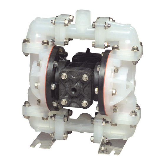
SERVICE & OPERATING MANUAL
Model S07
Non-Metallic Design Level 1
Table of Contents
Engineering Data and Temperature Limitations .......................................................1
Explanation of Pump Nomenclature .........................................................................2
Performance Curve ..................................................................................................3
Performance Curve, Trihedral Model .......................................................................4
Dimensions: S07 Non-Metallic .................................................................................5
Metric Dimensions: S07 Non-Metallic.......................................................................6
Principle of Pump Operation.....................................................................................7
Installation and Start-up............................................................................................7
Air Supply .................................................................................................................7
Air Valve Lubrication .................................................................................................7
Air Line Moisture.......................................................................................................7
Air Inlet and Priming .................................................................................................7
Between Uses ..........................................................................................................7
Installation Guide ......................................................................................................8
Troubleshooting ........................................................................................................9
Warranty ...................................................................................................................9
Important Safety Information ..................................................................................10
Material Codes ....................................................................................................... 11
Composite Repair Parts Drawing ...........................................................................12
Overlay Option Drawing .........................................................................................12
Available Service and Conversion Kits ...................................................................12
Composite Repair Parts List ...................................................................................13
Air Valve Assembly Drawing and Parts List ............................................................14
Air Valve Assembly Servicing .................................................................................15
Air Valve with Stroke Indicator Drawing and Parts List ...........................................16
Air Valve with Stroke Indicator Servicing ................................................................17
Pilot Valve Servicing, Assembly Drawing and Parts List .......................................18
WARREN RUPP
s07nmdl1sm-rev0513
, IDEX AODD, Inc. • A Unit of IDEX Corporation • 800 N. Main St., P.O. Box 1568, Mansfield, Ohio 44901-1568 USA
®
Telephone (419) 524-8388 • Fax (419) 522-7867 • www.warrenrupp.com
U.S. Patent #
400,210
5,996,627;
6,241,487
Solenoid Shifted Valve Drawing and Parts List ......................................................19
Solenoid Shifted Air Distribution Valve Option ........................................................20
Intermediate Assembly Drawing .............................................................................21
Intermediate Assembly Servicing ...........................................................................21
Modular Check Ball Valve Drawing ........................................................................22
Modular Check Ball Valve Servicing .......................................................................22
Modular Trihedral Check Valve Option Drawing and Parts List ..............................23
Modular Trihedral Check Valve Servicing ...............................................................24
Diaphragm Service Drawing, Non-Overlay.............................................................25
Diaphragm Service Drawing with Overlay .............................................................25
Diaphragm Servicing, Overlay Diaphragm Servicing ............................................26
Dual Port Option Drawing .......................................................................................27
Dual Porting Options ..............................................................................................28
Dual Porting of both suction and discharge ends of the pump ...............................28
Single Porting of the suction and dual porting of the pump discharge ...................28
Dual Porting of the suction and single porting of the pump discharge ...................28
Single Port Suction Repair Parts List .....................................................................29
Single Port Discharge Repair Parts List .................................................................29
Dual Port Suction and Discharge Repair Parts List ................................................29
Pumping Hazardous Liquids...................................................................................30
Converting the Pump for Piping the Exhaust Air ....................................................30
Exhaust Conversion Drawing .................................................................................30
Converted Exhaust Illustration................................................................................30
Pulse Output Kit Drawing, Option ...........................................................................31
Optional Muffler Configurations Drawing ................................................................32
CE Declaration of Conformity .................................................................................33
©Copyright 2013 Warren Rupp, Inc. All rights reserved.
Advertisement
Table of Contents


Need help?
Do you have a question about the S07B1P2PPNS000 and is the answer not in the manual?
Questions and answers