Sandpiper S05 Service & Operating Manual
Air-powered double-diaphragm pump
Hide thumbs
Also See for S05:
- Service & operating manual (36 pages) ,
- Service & operating manual (34 pages) ,
- Service & operating manual (23 pages)
Table of Contents
Advertisement
Quick Links
SERVICE & OPERATING MANUAL
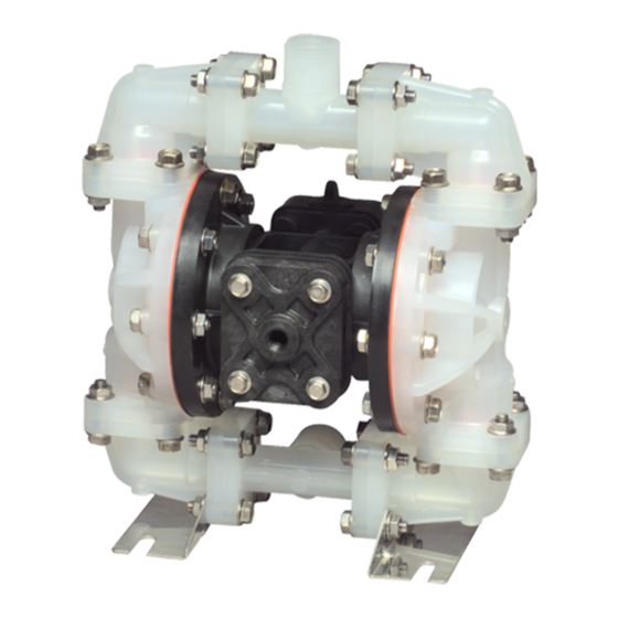
Model S05 Non-Metallic Design Level 1
Table of Contents
Engineering Data and Temperature Limitations ......................................................... 1
Explanation of Pump Nomenclature ......................................................................... 2
Performance Curve .................................................................................................. 3
Dimensions .............................................................................................................. 4
Metric Dimensions ................................................................................................... 5
Principle of Pump Operation .................................................................................... 6
Installation and Start-up ........................................................................................... 6
Air Supply ................................................................................................................ 6
Air Valve Lubrication ................................................................................................ 6
Air Line Moisture ...................................................................................................... 6
Air Inlet and Priming ................................................................................................. 6
Between Uses ......................................................................................................... 6
Installation Guide ..................................................................................................... 7
Troubleshooting ........................................................................................................ 8
Warranty .................................................................................................................. 8
Important Safety Information .................................................................................... 9
Material Codes ......................................................................................................... 9
Composite Repair Parts Drawing ............................................................................ 10
Overlay Option Drawing, Muffler Option Drawing .................................................... 10
Available Service and Conversion Kits ................................................................ 10
Composite Repair Parts List ................................................................................ 11
Air Distribution Valve Assembly Drawing ............................................................. 12
Air Distribution Valve Assembly Parts List ............................................................ 12
Air Distribution Valve Servicing ............................................................................ 13
Air Distribution Valve Assembly Drawing w/Stroke Indicator Option ................... 14
Air Distribution Valve w/Stroke Indicator Option Parts List ................................... 14
Air Distribution Valve w/Stroke Indicator Option Servicing ................................... 15
Solenoid Shifted Air Valve Drawing ..................................................................... 16
Solenoid Shifted Air Valve Parts List .................................................................... 16
WARREN RUPP
®
, INC. • A Unit of IDEX Corporation • P .O. Box 1568, Mansfield, Ohio 44901-1568 USA • Telephone (419) 524-8388 • Fax (419) 522-7867 • www.warrenrupp.com
520-211-000 2/01
CE
Solenoid Shifted Air Distribution Valve Option ..................................................... 17
Pilot Valve Assembly Drawing .............................................................................. 18
Pilot Valve Assembly Parts List ............................................................................. 18
Pilot Valve Servicing ............................................................................................. 19
Intermediate Assembly Drawing and Parts List ................................................... 20
Intermediate Assembly Servicing ......................................................................... 20
Modular Check Valve Drawing ............................................................................. 21
Modular Check Valve Servicing ........................................................................... 21
Diaphragm Service Drawing, Non-Overlay ......................................................... 22
Diaphragm Service Drawing, with Overlay .......................................................... 22
Diaphragm Servicing ............................................................................................ 23
Overlay Diaphragm Servicing .............................................................................. 23
Dual Port Option Drawing ..................................................................................... 24
Dual Porting Options ............................................................................................ 25
Dual porting of both suction and discharge ends of the pump ............................ 25
Single porting of the suction and dual porting of the pump discharge ................ 25
Dual porting of the suction and single porting of the pump discharge ................ 25
Single Port Suction Repair Parts List ................................................................... 26
Single Port Discharge Repair Parts List ............................................................... 26
Dual Port Suction and Discharge Repair Parts List ............................................. 26
Pumping Hazardous Liquids ................................................................................ 27
Converting the pump for piping the exhaust air ................................................... 27
Exhaust Conversion Drawing .............................................................................. 27
Converted Exhaust Illustration ............................................................................. 27
Pulse Output Kit Drawing ..................................................................................... 28
Pulse Output Kit Option ........................................................................................ 28
Exhaust Port or Auxiliary Muffler Setup ................................................................ 28
Integral Muffler Setup ........................................................................................... 28
Grounding the Pump ............................................................................................ 29
U.S. Patent #
400,210
5,996,627
©Copyright 2001 Warren Rupp, Inc. All rights reserved.
Advertisement
Table of Contents

Related Manuals for Sandpiper S05


Summary of Contents for Sandpiper S05
-
Page 1: Table Of Contents
SERVICE & OPERATING MANUAL U.S. Patent # Model S05 Non-Metallic Design Level 1 400,210 5,996,627 Table of Contents Engineering Data and Temperature Limitations ............1 Solenoid Shifted Air Distribution Valve Option ............. 17 Explanation of Pump Nomenclature ................. 2 Pilot Valve Assembly Drawing ................18 Performance Curve .................... -
Page 3: Performance Curve
For specific applications, always consult “Chemical Resistance Chart” Technical Bulletin *Definite reduction in service life. **Minimal reduction in service life at ends of range. SandPIPER II ® pumps are designed to be powered only by compressed air. 520-211-000 2/01 Model S05 Non-Metallic Design Level 1 Page 1... -
Page 4: Dimensions
Explanation of Pump Nomenclature S05 Non-Metallic · Design Level 1· Ball Valve Check Diaphragm/ Check Non-Wetted Shipping MODEL Pump Pump Valve Design Wetted Check Valve Valve Material Porting Pump Pump Weight Brand Size Type Level Material Materials Seat Options Options... -
Page 5: Metric Dimensions
Performance Curve, S05 Non-Metallic, Design Level 1 2 (3.5) 4 (7) 6 (10) 8 (13.5) 10 (17) 12 (20) 14 (24) 16 (27) U.S. Gallons per minute Liters per minute Capacity 520-211-000 2/01 Model S05 Non-Metallic Design Level 1 Page 3... -
Page 6: Principle Of Pump Operation
Dimensional tolerance: ± " DIMENSION Standard Pump 4 1/16" 7 1/16" Pulse Output Kit 5 13/16" 8 13/16" Mesh Muffler 5 3/4" 8 3/4" Sound Dampening Muffler 7" 9 15/16" 520-211-000 2/01 Model S05 Non-Metallic Design Level 1 Page 4... -
Page 7: Installation Guide
DIMENSION ARE AVAILABLE IN ½" BSPT TAPERED (INTERNAL) Standard Pump 103mm 179mm 1" BSPT TAPERED (EXTERNAL) Pulse Output Kit 148mm 224mm Mesh Muffler 146mm 222mm Sound Dampening Muffler 178mm 252mm 520-211-000 2/01 Model S05 Non-Metallic Design Level 1 Page 5... -
Page 8: Troubleshooting
When the spool performance. When the air supply line dryer to supplement the user’s air drying 520-211-000 2/01 Model S05 Non-Metallic Design Level 1 Page 6... -
Page 9: Important Safety Information
020-049-001 Lubricator 020-046-008 Air Dryer CAUTION The air exhaust should be piped to an area for safe disposition of the product being pumped, in the event of a diaphragm failure. 520-211-000 2/01 Model S05 Non-Metallic Design Level 1 Page 7... -
Page 10: Composite Repair Parts Drawing
Corrective Action: Disassemble and What to Check: Undersized suction chambers. Inspect for diaphragm rupture inspect the wetted chambers of the line. or loose diaphragm plate assembly. Refer pump. Remove or flush any obstructions. 520-211-000 2/01 Model S05 Non-Metallic Design Level 1 Page 8... -
Page 11: Composite Repair Parts List
364 ..E.P .D.M. Rubber. Color coded: BLUE Warren Rupp, Rupplon, SandPIPER, SandPIPER II, PortaPump, 365 ..Neoprene Rubber. Color coded: GREEN the air exhaust must be piped to an appropriate Wear ear and eye protection. -
Page 16: Solenoid Shifted Air Valve Drawing
(Connector not required for explosion proof coil; coil is integral with valve) 893-094-001 Solenoid Valve, NEMA 7/9, 24VDC 893-094-002 Solenoid Valve, NEMA 7/9, 24VAC/12VDC 893-094-003 Solenoid Valve, NEMA 7/9, 120VAC 893-094-004 Solenoid Valve, NEMA 7/9, 240VAC 520-211-000 2/01 Model S05 Non-Metallic Design Level 1 Page 16... -
Page 17: Solenoid Shifted Air Distribution Valve Option
SandPIPER pump, with one exception. This option provides a way to precisely control and monitor pump speed. BEFORE INSTALLATION Before wiring the solenoid, make certain it is compatible with your system voltage. 520-211-000 2/01 Model S05 Non-Metallic Design Level 1 Page 17... -
Page 18: Pilot Valve Assembly Drawing
770-065-175 Spacer 775-041-506 Spool, Pilot Valve 917-003-374 Wiper For Conductive Acetal pumps: 095-091-001 Pilot Valve Assembly 095-087-503 Body, Pilot Valve (includes all other items used on 095-091-000 Pilot Valve above) 520-211-000 2/01 Model S05 Non-Metallic Design Level 1 Page 18... -
Page 19: Pilot Valve Servicing
Replace the plungers in to the bushings. Push wipers and/or spacers as necessary. the plungers in as far as they will go. 520-211-000 2/01 Model S05 Non-Metallic Design Level 1 Page 19... -
Page 20: Intermediate Assembly Drawing And Parts List
ITEM PART NUMBER DESCRIPTION 114-023-551 Bracket, Intermediate 135-036-506 Bushing, Plunger 560-001-360 O-Ring 675-042-115 Ring, Retaining* *NOTE: It is recommended that when plunger components are serviced, new retaining rings be installed. 520-211-000 2/01 Model S05 Non-Metallic Design Level 1 Page 20... -
Page 21: Modular Check Valve Drawing
Replace any worn or damaged parts as necessary. 520-211-000 2/01 Model S05 Non-Metallic Design Level 1 Page 21... -
Page 22: Diaphragm Service Drawing, Non-Overlay
Diaphragm Service Drawing, Diaphragm Service Drawing, Non-Overlay with Overlay Cross Section of Diaphragm THE DIAPHRAGMS FOR BOTH CONFIGURATIONS SHOWN ABOVE ARE TO BE INSTALLED WITH CONVOLUTIONS FACING TOWARDS CENTER OF PUMP 520-211-000 2/01 Model S05 Non-Metallic Design Level 1 Page 22... -
Page 23: Diaphragm Servicing
Make sure the bumper (item loosely into a vise. Use a ¾" wrench or 6) is installed over the diaphragm rod. socket to remove the outer diaphragm Thread the stud of the remaining 520-211-000 2/01 Model S05 Non-Metallic Design Level 1 Page 23... -
Page 24: Dual Port Option Drawing
1" NPT or 1" BSPT External ½" NPT or ½" BSPT Internal Connection Illustration for Single Port Suction Illustration for Dual Port Suction and with Dual Port Discharge Single or Dual Port Discharge 520-211-000 2/01 Model S05 Non-Metallic Design Level 1 Page 24... -
Page 25: Dual Porting Options
90° increments Dual Porting Drawing.) (see arrows and optional positioning in the Dual Porting Drawing. NOTE: See Repair Parts List on next page. 520-211-000 2/01 Model S05 Non-Metallic Design Level 1 Page 25... -
Page 26: Single Port Suction Repair Parts List
Manifold (installed in top position) BSPT 115-144-333 Bracket, Free Standing (replaces 115-140-333) 171-068-115 Capscrew, Flanged 5/16-18 X 1.63 171-068-308 Capscrew, Flanged 5/16-18 X 1.63 * Quantities change from Composite Repair Parts List. 520-211-000 2/01 Model S05 Non-Metallic Design Level 1 Page 26... -
Page 27: Pumping Hazardous Liquids
(items 1-G and 1-F). The " NPT molded EXHAUST PIPING LIQUID threads in the air distribution valve body LEVEL (item 1-A). Piping or hose may now be installed. SUCTION LINE Illustration #3 520-211-000 2/01 Model S05 Non-Metallic Design Level 1 Page 27... -
Page 28: Pulse Output Kit Drawing
See the individual kits listed on the Pump Repair Parts List for further information. Exhaust Port or Auxiliary Integral Muffler Setup Muffler Setup Pulse Output Kit Muffler Cap Adapter Plate Pulse Output Kit 520-211-000 2/01 Model S05 Non-Metallic Design Level 1 Page 28... -
Page 29: Grounding The Pump
WARNING Take action to prevent static sparking. Fire or explosion can result, especially when handling flammable liquids. The pump, piping, valves, containers or other miscellaneous equipment must be grounded. 520-211-000 2/01 Model S05 Non-Metallic Design Level 1 Page 29...
Need help?
Do you have a question about the S05 and is the answer not in the manual?
Questions and answers