
Related Manuals for Linde ARCLINE Cool 2


Summary of Contents for Linde ARCLINE Cool 2
-
Page 1: Operating Instructions
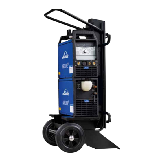
Operating instructions Air-cooling units for water-cooled welding torches Cool 2 099-008600-55801 Observe additional system documents! 29.08.2017... -
Page 2: General Instructions
For this reason, we do not accept any responsibility or liability for losses, damages or costs arising from incorrect installation, improper operation or incorrect usage and maintenance or any actions connected to this in any way. © Linde AG Gases Division Germany Seitnerstraße 70 82049 Pullach, Deutschland The copyright to this document remains the property of the manufacturer. - Page 3 Contents Notes on the use of these operating instructions Contents 1 Contents ................................3 2 For your safety ..............................5 Notes on the use of these operating instructions ................5 Explanation of icons ..........................6 Part of the complete documentation ....................7 3 Intended use ..............................
- Page 4 Contents Notes on the use of these operating instructions Fixing the pump shaft (coolant circuit) ....................21 8 Technical data ..............................23 LINDE ARCLINE Cool 2 ......................... 23 ® 099-008600-55801 29.08.2017...
-
Page 5: For Your Safety
For your safety Notes on the use of these operating instructions For your safety Notes on the use of these operating instructions DANGER Working or operating procedures which must be closely observed to prevent imminent serious and even fatal injuries. •... -
Page 6: Explanation Of Icons
For your safety Explanation of icons Explanation of icons Symbol Description Symbol Description Indicates technical aspects which the Activate and release/tap/tip user must observe. Switch off machine Release Switch on machine Press and keep pressed Switch Wrong Turn Numerical value – adjustable Correct Menu entry Signal light lights up in green... -
Page 7: Part Of The Complete Documentation
For your safety Part of the complete documentation Part of the complete documentation These operating instructions are part of the complete documentation and valid only in combination with all other parts of these instructions! Read and observe the operating instructions for all system components, especially the safety instructions! The illustration shows a general example of a welding system. -
Page 8: Intended Use
We can only guarantee smooth and trouble-free operation when used in conjunction with the welding machines, welding torches, coolants and accessory components from our range. For operation only with the following equipment 3.1.1 • LINDE ARCLINE® TPI 300 puls DC • LINDE ARCLINE® TPI 300 puls AC/DC Documents which also apply Warranty 3.2.1... -
Page 9: Declaration Of Conformity
Intended use Documents which also apply Declaration of Conformity 3.2.2 The labelled machine complies with the following EC directives in terms of its design and construction: • Low Voltage Directive (LVD) • Electromagnetic Compatibility Directive (EMC) • Restriction of Hazardous Substance (RoHS) In case of unauthorised changes, improper repairs, non-compliance with specified deadlines for "Arc Welding Equipment –... -
Page 10: Machine Description – Quick Overview
Machine description – quick overview Front view Machine description – quick overview Front view Figure 4-1 Item Symbol Description Screw connector Connects cooling module and welding machine Coolant tank cap Coolant tank Quick connect coupling, red Coolant return from the welding torch Quick connect coupling, blue Coolant supply to the welding torch Cooling air inlet... -
Page 11: Rear View
Machine description – quick overview Rear view Rear view Figure 4-2 Item Symbol Description Connector plug, 4-pole Cooling unit voltage supply Connector plug, 8-pole Cooling unit control lead Automatic cut-out of coolant pump key button press to reset a triggered fuse Cooling air outlet 099-008600-55801 29.08.2017... -
Page 12: Design And Function
Design and function Assembly/disassembly Design and function WARNING Risk of injury from electrical voltage! Contact with live parts, e.g. power connections, can be fatal! • Observe the safety information on the first pages of the operating instructions! • Commissioning must be carried out by persons who are specifically trained in handling power sources! •... -
Page 13: Connecting The Supply Lines
Design and function Transport and installation Connecting the supply lines 5.1.1 Control and supply lead to the welding machine The cooling module and welding machine are connected using two leads. • Insert the control lead plug on the welding machine. •... -
Page 14: Welding Torch Cooling System
Design and function Functional characteristics Welding torch cooling system 5.2.3 Insufficient frost protection in the welding torch coolant! Depending on the ambient conditions, different liquids are used for cooling the welding torch > see 5.2.3.1 chapter. Coolants with frost protection (KF 37E or KF 23E) must be checked regularly to ensure that the frost protection is adequate to prevent damage to the machine or the accessory components. -
Page 15: Functional Characteristics
Design and function Functional characteristics Functional characteristics Overloading the coolant pump! The cooling unit must not be put into operation without a welding torch connected, as otherwise the coolant pump will be destroyed due to thermal overload (the coolant cannot circulate in the coolant circuit). •... -
Page 16: Welding Torch Connection
Design and function Functional characteristics • Unscrew and remove the coolant tank sealing cover. • Check filter sieve insert for dirt, clean if necessary and reinsert into position. • Top up coolant to the filter sieve insert, close sealing cover again. The level of coolant must never fall below the “min”... -
Page 17: Maintenance, Care And Disposal
Maintenance, care and disposal General Maintenance, care and disposal General DANGER Risk of injury due to electrical voltage after switching off! Working on an open machine can lead to fatal injuries! Capacitors are loaded with electrical voltage during operation. Voltage remains present for up to four minutes after the mains plug is removed. -
Page 18: Maintenance Work, Intervals
Maintenance, care and disposal Maintenance work, intervals Maintenance work, intervals Daily maintenance tasks 6.3.1 Visual inspection • Mains supply lead and its strain relief • Gas cylinder securing elements • Check hose package and power connections for exterior damage and replace or have repaired by specialist staff as necessary! •... -
Page 19: Annual Test (Inspection And Testing During Operation)
Maintenance, care and disposal Disposing of equipment Annual test (inspection and testing during operation) 6.3.3 The welding machine may only be tested by competent, capable personsl. A capable person is one who, because of his training, knowledge and experience, is able to recognise the dangers that can occur while testing welding power sources as well as possible subsequent damage and who is able to implement the required safety procedures. -
Page 20: Rectifying Faults
Rectifying faults Checklist for rectifying faults Rectifying faults All products are subject to rigorous production checks and final checks. If, despite this, something fails to work at any time, please check the product using the following flowchart. If none of the fault rectification procedures described leads to the correct functioning of the product, please inform your authorised dealer. -
Page 21: Vent Coolant Circuit
Rectifying faults Vent coolant circuit Vent coolant circuit To vent the cooling system always use the blue coolant connection, which is located as deep as possible inside the system (close to the coolant tank)! Figure 7-1 Fixing the pump shaft (coolant circuit) WARNING Do not carry out any unauthorised repairs or modifications! To avoid injury and equipment damage, the unit must only be repaired or modified by specialist,... - Page 22 Rectifying faults Fixing the pump shaft (coolant circuit) Figure 7-2 • Switch off machine at the main switch. • Insert a plain slot screwdriver with a maximum tip width of 6.5 mm through one of the openings and place in the centre of the pump shaft. Turn the screwdriver clockwise until the pump shaft can be easily rotated again.
-
Page 23: Technical Data
Technical data LINDE ARCLINE® Cool 2 Technical data Technical data limit values The limit values determination from technical data is calculated taking account of the combined system as a whole (cooling unit and welding machine). LINDE ARCLINE Cool 2 ®...
Need help?
Do you have a question about the ARCLINE Cool 2 and is the answer not in the manual?
Questions and answers