
Related Manuals for Linde Ryval 251 aXe


Summary of Contents for Linde Ryval 251 aXe
- Page 1 MIG/MAG WELDING MACHINES Ryval 251 aXe Ryval 261 aXe Ryval 280 aXe Ryval 320 aXe Ryval 400 aXe MINOR2 - MAJOR – SYNERGY BASIC INSTRUCTION MANUAL Linde AG, Linde Gas Deutschland 2014 © Ryval 251-261-280-320-400 EN1.doc...
-
Page 2: Table Of Contents
TECHNICAL DATA ................. 8 ACCESSORIES ..................10 DESCRIPTION OF THE APPLIANCE ..........11 GETTING STARTED ................18 WELDING ..................... 22 ROUTINE MAINTENANCE & INSPECTION ......... 27 10. STATEMENT OF WARRANTY ............. 28 11. DISPOSAL .................... 28 Linde AG, Linde Gas Deutschland 2014 ©... -
Page 3: Introduction
3/29 INTRODUCTION Congratulations on your new Linde AG, Linde Gas Deutschland product. We are proud to have you as our customer and will strive to provide you with the best service and reliability in the industry. This Operating Manual has been designed to instruct you on the correct use and operation of your Linde AG, Linde Gas Deutschland product. -
Page 4: Safety Instructions And Warnings
Use an air-supplied respirator if ventilation is not adequate to remove all fumes and gases. The kinds of fumes and gases from the plasma arc depend on the kind of metal being used, coatings on the metal, and the different processes. Linde AG, Linde Gas Deutschland 2014 ©... - Page 5 EN 60974-1 Standard: Open-circuit voltage. During the operation of the machine, the highest voltage, with which it is possible to come into contact, is the open-circuit voltage between the clamps. Linde AG, Linde Gas Deutschland 2014 ©...
- Page 6 Domestic electronic appliances (radios, TVs, videos, telephones, burglar alarms, etc.). Computers, robots, electro-medical instruments and life-support systems. Radio-television transmitters and receivers. Linde AG, Linde Gas Deutschland 2014 ©...
-
Page 7: Conditions Of Use
Never aim the torch against the eyes, body or other person. CONDITIONS OF USE This equipment must only be used by qualified personnel. During installation, any electric work must only be carried out by trained Linde AG, Linde Gas Deutschland 2014 ©... -
Page 8: Technical Data
EN 60 974-1 EN 60 974-1 Dimensions (w x l x h) 500x868x80 500x868x80 compact Dimensions (w x l x h) generator Weight compact Weight generator Wire speed m/min 1 - 19 1 - 19 Linde AG, Linde Gas Deutschland 2014 ©... - Page 9 1 - 19 Input voltage U V/Hz 24/1~50 Input current I Welding current I (DZ=100%) Welding current I (DZ=60%) Spool diameter Spool weight Protection IP 21S Dimensions (w x l x 264x704x507 Linde AG, Linde Gas Deutschland 2014 ©...
-
Page 10: Accessories
Torches with UP-DOWN remote control Welding torches (see the table below) Torch type Cooling Welder MB 24KD Ryval 251-280 aXe MB 36KD Ryval 320 aXe MB 36KD Ryval 400 aXe Linde AG, Linde Gas Deutschland 2014 ©... -
Page 11: Description Of The Appliance
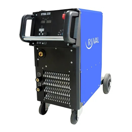
11/29 DESCRIPTION OF THE APPLIANCE MAIN PARTS Fig. 1 - Main parts of Ryval compact aXe Fig. 2 - Main parts of Ryval compact aXe Linde AG, Linde Gas Deutschland 2014 ©... - Page 12 12/29 Fig. 3 – Main parts of Ryval Separate aXe Fig. 4 - Main parts of Ryval Separate aXe ON / OFF Switch Switch coarse Switch smooth Linde AG, Linde Gas Deutschland 2014 ©...
- Page 13 Cable Bundle Cable Bundle Generator LED ON Indicator Gas heater connector CONTROL PANEL - OVERVIEW Fig. 5 - Ryval 400 aXe control panel PCB - encoder ON / OFF Switch Switch coarse Switch smooth Linde AG, Linde Gas Deutschland 2014 ©...
- Page 14 default RESET (together with button X1) Button Switches between 2S or 4S, Press more than 3s will initiate spot or interval mode Enters secondary parameters (together with button X5) Green LED 2 Stroke Linde AG, Linde Gas Deutschland 2014 ©...
- Page 15 Position of the choke (just SYNERGY) LED – The mode of selecting the program is active (just SYNERGY). Green LED – lights if on the display X8 is displayed material thickness, (just SYNERGY). LED - 4 Stroke Linde AG, Linde Gas Deutschland 2014 ©...
- Page 16 Selects program No (just SYNERGY) Sets secondary parameters BASIC CONTROL PANEL Fig. 7 – BASIC control panel On/Off Switch Switch Coarse Switch Fine Wire speed Spot time Interval time LED ON LED thermal protection Linde AG, Linde Gas Deutschland 2014 ©...
- Page 17 EURO connector Roll, Plastic cup PS 2(W) PS 4(W) 2-rolls 4-rolls a = 22 mm a = 22 mm b = 30 mm b = 30 mm Grove type Wire diameter Item No Linde AG, Linde Gas Deutschland 2014 ©...
-
Page 18: Getting Started
In case your appliance is a model with separate wire feeder connect the feeder with the generator by means of cable bundle A21. Plug the mains plug to 3x400 V mains. Linde AG, Linde Gas Deutschland 2014 ©... - Page 19 Adjust the pressure nut that way that it provides constant movement of wire but it does not deform wire. INSERTING THE WELDING WIRE INTO THE WELDING TORCH Fig. 11 – Welding torch connecting Linde AG, Linde Gas Deutschland 2014 ©...
- Page 20 CHANGING THE WIRE FEEDER ROLL Every wire feeding roll in Linde AG, Linde Gas Deutschland machines can be used for two different diameters of welding wire – the rolls have two grooves.
- Page 21 Fig. 14 – Gas fitting F1 Gas Cylinder F2 Cylinder Valve F3 Gas heater connector F4 Pressure Reducer F5 High Pressure Manometer F6 Low Pressure Manometer F7 Adjusting Screw Linde AG, Linde Gas Deutschland 2014 ©...
-
Page 22: Welding
To select the current (that is linked to the wire speed) use the encoder V1. WELDING MODES Machines works in four modes: continuous two stroke (2T) continuous four stroke (4T) spot welding interval welding Linde AG, Linde Gas Deutschland 2014 ©... - Page 23 FOUR STROKE BASIC Set the potentiometers V7 into any position 1 – 10. Potentiometer V6 must be in 0 position. SPOT AND INTERVAL WELDING DIGITAL Keep pressing the button X3 (2T/4T) for at least 3s Linde AG, Linde Gas Deutschland 2014 ©...
- Page 24 The spot welding mode is being used for welding short welds of the same length. The pressing the torch button activates the time circuit that starts and end the welding procedure. Linde AG, Linde Gas Deutschland 2014 ©...
- Page 25 The welder select the parameter that he knows by means the button X5 and the encoder X20 (Current in A, wire speed in m/min or material thickness). Then the welder can the recommended settings see on the right display (see Fig. 17). Linde AG, Linde Gas Deutschland 2014 ©...
- Page 26 First left figure – coarse voltage A - B (JUST Ryval 400). Second left figure - fine voltage 1 - 9, the tenth position of the switch is signed as „0“; Ryval 320 shows numbers 1-12. Third left figure – choke position. Linde AG, Linde Gas Deutschland 2014 ©...
-
Page 27: Routine Maintenance & Inspection
A ‘competent person’ must be a person who has acquired through training, qualification or experience, or a combination of them, the knowledge and skills enabling that person to safely carry out a risk assessment and repairs to the electrical equipment in question. Linde AG, Linde Gas Deutschland 2014 ©... -
Page 28: Statement Of Warranty
Linde AG, Linde Gas Deutschland will repair or replace, at its discretion, any warranted parts or components that fail due to defects in material or workmanship within the warranty period. The warranty period begins on the date of sale to the end user. - Page 29 Linde AG, Linde Gas Deutschland 2014 ©...
Need help?
Do you have a question about the Ryval 251 aXe and is the answer not in the manual?
Questions and answers