Table of Contents
Advertisement
NORTH AMERICA
3130 East Miraloma Avenue
Anaheim, CA 92806 USA
USA and Canada –
Phone: 800-368-9700
Fax: 800-832-4888
Other Locations – Phone: (001)-714-632-7100; Fax: (001)-714-632-1044
©Premier Mounts 2008
9531-007-001-06
INSTALLATION INSTRUCTIONS
AM3/AM3-B
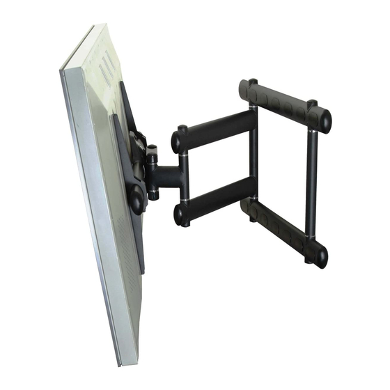
Universal Swingout Arm
EUROPE
Swallow House,
Shilton Industrial Estate,
Shilton, Coventry, England CV79JY
Phone: +44 (0) 2476 614700
Fax: +44 (0) 2476 614710
AUSTRALIA, NEW ZEALAND, OCEANIA
(DISTRIBUTOR)
P.O. Box 295
Mordialloc Victoria 3195
Australia
Phone: 039586 6330
www.premiermounts.com.au
Advertisement
Table of Contents

Summary of Contents for Premier Mounts Swingout Arm AM3
-
Page 1: Installation Instructions
NORTH AMERICA 3130 East Miraloma Avenue Anaheim, CA 92806 USA USA and Canada – Phone: 800-368-9700 Fax: 800-832-4888 Other Locations – Phone: (001)-714-632-7100; Fax: (001)-714-632-1044 ©Premier Mounts 2008 9531-007-001-06 INSTALLATION INSTRUCTIONS AM3/AM3-B Universal Swingout Arm EUROPE Swallow House, Shilton Industrial Estate,... -
Page 2: Table Of Contents
PROPERTY DAMAGE. KEEP THESE INSTALLATION INSTRUCTIONS IN AN EASILY ACCESSIBLE LOCATION FOR FUTURE REFERENCE. PREMIER MOUNTS DOES NOT WARRANT AGAINST DAMAGE CAUSED BY THE USE OF ANY PREMIER MOUNTS PRODUCT FOR PURPOSES OTHER THAN THOSE FOR WHICH IT WAS DESIGNED OR DAMAGE CAUSED BY UNAUTHORIZED ATTACH-... -
Page 3: Parts List
This wall mount is shipped with all proper installation hardware and components. Make sure that none of these parts are missing and/or damaged before beginning installation. If there are parts missing and/or damaged, please stop the installation and contact Premier Mounts (800-368-9700). AM3 Universal Barcket Arms (Qty 2) 5/16”... - Page 4 (Qty 8) M4 x 16 (Qty 8) M4 x 25 (Qty 8) M5 x 12 (Qty 8) M5 x 16 (Qty 8) M5 x 20 (Qty 8) M5 x 25 M5 x 50 (Qty 8) M6 x 16 (Qty 8) M6 x 20 Page 4 M6 x 30...
- Page 5 AM3/AM3-B The nylon spacers may be stacked to achieve proper spacing. Installation Instructions 1/4" Nylon spacers (large) (Qty 8) 1/2" Nylon spacers (large) (Qty 12) 5/16" Flat washers (metal) (Qty 8) 1" Nylon Spacers (Qty 8) 1/4" Nylon spacers (small) (Qty 8) 9/16"...
-
Page 6: Thread Depth Indicator
Thread Depth Indicator 1. Insert the thread depth indicator (supplied) through the thread inserts found on the back of the fl at panel to make sure the inserts measure the same full depth and mark it (Figure 1). 2. Locate the correct diameter screw for the thread insert. Compare your marking to the screws (supplied). 3. -
Page 7: Mount Orientation
AM3/AM3-B Mount Orientation The AM3/AM3-B Plasma Mount has the built-in capability of mounting with the swingout arm on either the left or right-hand side. WHEN MOUNTING THE AM3, THE SIDE THAT THE SWINGOUT ARM IS LOCATED ON MUST HAVE A LAG BOLT MOUNTED ON AT LEAST ONE SIDE (SEE FIGURE 1), TOP AND BOTTOM. -
Page 8: Mount Installation
Mount Installation Before proceeding with the mount installation, you should already have the mounting holes pre-drilled. Please use the template (supplied) and follow the instructions. For ease of installation, it is recommended that two people perform the installation. WHEN MOUNTING THE AM3, THE SIDE THAT THE SWINGOUT ARM IS LOCATED ON MUST HAVE A LAG BOLT MOUNTED ON AT LEAST ONE SIDE ( FIGURE 4, PAGE 8), TOP AND BOTTOM. -
Page 9: Nose Piece Orientation
AM3/AM3-B Nose Piece Orientation Right Side Orientation Back Side of Nose Piece Step 1. Once the mount has been oriented and mounted to the wall, remove the nose piece by removing the tensions bolts. After loosening the tension bolts, be sure that the nose piece is held together tightly before rotating. Step 2. -
Page 10: Universal Mounting Bracket Assembly
Universal Mounting Bracket Assembly Step 1. Place the universal bracket bar and the universal brackets on a flat surface. Step 2. Slide the universal brackets onto the universal bracket bar (as shown in Figure 9) with the set screws facing up. At this time, do not tighten the set screws that are located on the universal bracket. -
Page 11: Attaching The Display
AM3/AM3-B Attaching the Display ONCE THE UNIVERSAL BRACKET BAR ASSEMBLY HAS BEEN ATTACHED TO THE DISPLAY, IT IS RECOMMENDED THAT TWO PEOPLE MOUNT THE DISPLAY, AS THE UNIT IS HEAVY AND, IF DROPPED, WILL DAMAGE THE MOUNT, THE DISPLAY, AND/OR PERSONNEL. Figure 10 Figure 12 Step 2. -
Page 12: Securing The Display
Securing the Display Once the two units have been secured together, the two (2) M6 x 30mm Phillips Head locking screws must be installed in the noted location (Figure 14) to prevent any movement. Universal Bracker Bar M6 x 30mm Phillips Head Screw Swingout Arm... -
Page 13: Tilt Positioning
AM3/AM3-B Tilt Positioning To adjust the display, loosen the tension bolts no more than ½ turn, make the adjustments and then tighten the tension bolts. When tilt positioning is needed to adjust the display, place a hand at the top corner of the display and the other hand at the bottom of the display (Figure 15). -
Page 14: Technical Specifications
AM3/AM3-B Technical Specification All measurements are in inches(mm). Page 14 Installation Instructions... -
Page 15: Warranty
What Premier Mounts Will Do At the sole option of Premier Mounts, Premier Mounts will repair or replace any product or product part that is defective. If Premier Mounts chooses to replace a defective product or part, a replacement product or part will be shipped to you at no charge, but you must pay any labor costs.


Need help?
Do you have a question about the Swingout Arm AM3 and is the answer not in the manual?
Questions and answers