Xinje DS2 series Manual
Hide thumbs
Also See for DS2 series:
- User manual (99 pages) ,
- User manual (98 pages) ,
- Manual (59 pages)

Subscribe to Our Youtube Channel
Related Manuals for Xinje DS2 series


Summary of Contents for Xinje DS2 series
- Page 1 DS2 series servo drive Manual WUXI XINJE ELECTRIC CO., LTD. Data No.: SC209 20130116 1.0...
- Page 3 ►► Safety notes Confirmation Do not use the drivers that are broken, lack of parts or wrong types. Installation Make sure all the external powers are cut off before install the drivers. Wiring Please cut off all the powers before wiring. ...
- Page 4 DS2 – 2 0P7 – AS Series name Configuration: DS2:compact model Motor capacity AS/AS2/AS6 Voltage level 0P2: 0.2KW BS/BS6 2: 220V 0P4: 0.4KW BSW/BSW6 4:380V 0P7: 0.75KW 1P5:1.5 KW 2P3:2.3 KW 3P0:3.0 KW (2) Servo motor MS -80 ST - M 02430 A Z- 2 0P7 Power Voltage Power-loss brake...
- Page 5 3. Specification (1) servo motor Voltage level 220V 60ST- 80ST- Motor type MS- M00630 M01330 M02430 □□-20P2 □□-20P4 □□-20P7 1003 0004 1004 0011 1011 Motor code 0.75 Rated power (KW) Rated current(A) 3000 3000 3000 3000 3000 Rated speed(rpm) 4000 4000 4000 4000...
- Page 6 Voltage level 220V 110ST- 80ST- 90ST- Motor type MS- M04030 M05030 M03520 M02430 □□-21P2 □□-21P5 □□-20P7 0031 0032 0012 0021 Motor code Rated power (KW) 0.75 0.75 Rated current (A) 3000 3000 Rated seed (rpm) 2000 3000 3500 3500 Max speed (rpm) 2500 4000 Rated torque(N·...
- Page 7 temperature Environment Under 90% RH(no condensation) humidity Voltage level 220V 130ST- M06025 M10015 M07725 Motor type MS- □□-21P5 □□-22P0 0042 1042 0044 0043 Motor code Rated power (KW) Rated current(A) 2500 2500 1500 2500 Rated speed (rpm) 3000 3000 2000 3000 Max speed(rpm)...
- Page 8 Motor insulation level Class B(130℃) Protection level IP65 Environment -20℃~+50℃ temperature condition Environment Under 90% RH(no condensation) humidity Voltage level 220V 380V 130ST- 110ST- 130ST- M15015 M04030 M05030 M06025 Motor type MS- □□-22P3 □□-41P2 □□-41P5 □□-41P5 0046 0131 0132 0142 Motor code Rated power(KW)...
- Page 9 2500 Encoder line number(PPR) Pole pairs Motor insulation level Class B(130℃) Protection level IP65 Environment -20℃~+50℃ temperature condition Environment Under 90% RH(no condensation) humidity Voltage level 380V 130ST- 180ST- Motor type MS- M10015 M10030 M19015 M20015 □□-41P5 □□-43P0 □□-43P0 □□-43P0 0144 1148 0156...
- Page 10 IP65 Environment -20℃~+50℃ temperature Use condition Environment Under 90% RH(no condensation) humidity (2) servo drive DS2 series 220V Servo element DS2 series 380V Incremental encoder (2500 ppr) Suitable encoder DS2-2□P□-□: single/three phases AC200~240V, 50/60Hz DS2-4□P□-□: three-phases AC380~400V, 50/60Hz 【note:DS2-2□P□-□: Input power Under 1.5KW (not including 1.5KW)...
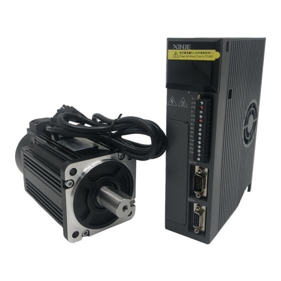
- Page 11 condition Humidity Under 90% RH(no condensation) Vibration resistance/impact 4.9m/s / 19.6m/s resistance Structure Foundation installation 4. Parts introduction (1) Servo motor Encoder Frame Flange Output shaft...
- Page 12 (2) Servo drive POWER Light when power on Panel display Display the servo state, parameter, alarm PUL- PUL+ DIR- DIR+ Panel buttons For parameter settings +24V Pulse, direction, I/O signal Power and motor terminal Drive and motor power terminal I/O, analog, position feedback signal Encoder terminal...
- Page 13 通讯端口(RS232通讯) Communication port 可连接电脑和触摸屏 (RS232 communication ) can connect to computer and touch screen ►► Installation 1. Servo motor MS series servo motors can be installed either horizontally or vertically. The service life of the servo motor can be shortened or unexpected problems might occur if it is installed incorrectly or in an inappropriate location.
- Page 14 (2) Installation location Free of corrosive or explosive gases. Well-ventilated and free of dust and moisture. Ambient temperature of 0° to 50° C. Relative humidity (r.h.) of 20 to 80% with no condensation. Accessible for inspection and cleaning. (3) Concentricity Please use coupling when connecting to machine;...
- Page 15 0.2 to 0.3mm 2. Servo drive The DS2 series servo drivers are base-mounted servo drivers. Incorrect installation will cause problems. Follow the installation instructions below: (1) Storage temperature Store the servo driver within -20~+85℃...
- Page 16 Installation at a Site Corrosive gas does not have an immediate effect on the servo drivers, Exposed but will eventually cause electronic components and terminals to Corrosive Gas malfunction. Take appropriate action to avoid corrosive gas. Other Situations Do not install the servo driver in hot and humid locations or locations subject to excessive dust or iron powder in the air.
- Page 17 PUL- PUL- PUL- PUL- PUL+ PUL+ PUL+ PUL+ DIR- DIR- DIR- DIR- DIR+ DIR+ DIR+ DIR+ +24V +24V +24V +24V Servo drive direction Install the servo driver perpendicular to the wall and make the front panel towards operator. Cooling Please leave enough space as the above diagram to ensure cooling by fans or natural ventilation.
- Page 18 Humidity: 90%RH or less Vibration: 4.9m/s No condensation and Freezing Ambient Temperature for Long-term reliability: 50° C maximum to use ►► Dimensions 1. Servo motor 60 series motor installation dimensions Unit: mm Type Normal With brake MS-60ST-M00630□□-20P2 MS-60ST-M01330□□-20P4...
- Page 19 80 series motor installation dimensions Unit: mm Type Normal With brake MS-80ST-M02430□□-20P7 MS-80ST-M03520□□-20P7...
- Page 20 90 series motor installation dimensions Unit: mm Type Normal With brake MS-90ST-M02430□□-20P7...
- Page 21 110 series motor installation dimensions Unit: mm Type Normal With brake MS-110ST-M04030□□-21P2 MS-110ST-M05030□□-21P5 MS-110ST-M04030□□-41P2 MS-110ST-M05030□□-41P5...
- Page 22 130 series motor installation dimensions Unit: mm Type Normal With brake MS-130ST-M06025□□-21P5 MS-130ST-M10015□□-21P5 MS-130ST-M07725□□-22P0 MS-130ST-M15015□□-22P3 MS-130ST-M06025□□-41P5 MS-130ST-M10015□□-41P5 MS-130ST-M10030□□-43P0...
- Page 23 180 series motor installation dimensions Unit: mm Type Normal With brake MS-180ST-M19015□□-43P0 MS-180ST-M20015□□-43P0...
- Page 24 2. Servo drive(unit: mm) DS2-20P□-AS/AS6, DS2-20P4-BS/BS6 DS2-21P5-AS/AS6, DS2-22P3-AS/AS6, DS2-41P5-AS/AS6, DS2-21P5-AS2...
- Page 25 85.0 198.3 DS2-43P0-AS/AS6 DS2-20P7-BSW/BSW6 70.0 59.0...
- Page 26 ►► Wiring 1. Main circuit DS2-20P2-AS/AS6, DS2-20P4-AS/AS6, DS2-20P7-AS/AS6 The terminal function of main circuit: Terminal Function Explanation L1/L2/L3 Power input of main single-phase 3-phase circuit 200~240V, 50/60Hz Ground terminal Connect to ground terminal of motor P+, PB Regeneration brake Connect the regeneration resistor resistor...
- Page 27 DS2-20P4-BS/BS6 According to the order from top to bottom,the functions of the main circuit are as followed: Terminal Function Explanation 200 ~240V, Power input single-phase main circuit 50/60Hz ● Empty pin U, V, W Motor terminal Connect to motor; Regenerative Connect the external regeneration P+, PB...
- Page 28 DS2-20P7-BSW/BSW6 Terminal Function Explanation 200 ~240V, Power input of main single-phase circuit 50/60Hz ● Empty Pin U, V, W Motor terminal Connect to the motor P+, D, C internal Short connect the terminal P+ regeneration resistor and D , disconnect P+ and C; Set P0-10=0 external Connect regeneration resistor to...
- Page 29 3. I/O terminal (CN0, CN1) The connector is looked at the soldering terminal: CN1(DB15) P+5V P+24V D+5V D+24V +24V CN0, CN1 Terminal CN0 terminals Name Contents Name Contents Pulse input P+ Input terminal 2 difference P+5V Input terminal 3 input P+ Open collector P+24V...
- Page 30 +24V difference D+5V Output terminal 1 input Open collector D+24V Output terminal 2 input Ground of output Input terminal 1 terminal CN1(DB15)terminals Name Contents Name Contents Encoder output Reservation Encoder output Reservation Torque analog Input terminal 5 T-REF input Speed analog Output terminal 3...
- Page 31 CN1(DB15)terminals ( Note: special for DS2-20P4-BS/BS6 DS2-20P7-BSW/BSW6 DS2-21P5-AS2) Name Explanation Reservation Reservation Input terminal 5 Output terminal 3 4. I/O signals (1) Input signal Item Input terminals Function Digital input SI1~SI5 Multi-functional input terminals Pulse input P-/P+5V/P+24V P2-00=0: positive pulse P2-00=2: pulse D-/D+5V/D+24V P2-00=0: negative pulse...
- Page 32 5. CN2 terminals The connector is looked at the soldering terminal: Encoder terminal Encoder terminal 60, 80, 60, 80, Drive Drive 110,130, Name Name 110,130,180 terminal terminal 180series Series series motor Series motor motor motor Shield 6. Communication port COM1 COM1 is RS232 port which can be used to connect PC for debugging.
- Page 33 All types Terminal Name Explanation RS232 send RS232 receive RS232 ground (5-pin port) Note: please use the cable offered by XINJE company. COM2 The COM2 position of each type: Type Port Mark mode DS2-2□P□-AS/AS6 A (CN1-14) This port cannot be used with RS485 DS2-4□P□-AS/AS6...
- Page 34 0:8 P0-04.1 Data bit 0:2 bits;2:1 bit P0-04.2 Stop bit 0~2 P0-04.3 Parity bit 0:no parity 1:odd parity 2:even parity Modbus station no. can be set through P0-03. Parameter Function Unit Default setting Range - 1~255 P0-03 Modbus station no. Note: the above parameters will be worked after re-power on.
- Page 35 DS2-20P7-BSW/BSW6 Connect the regeneration resistor to The internal resistor DS2-21P5-AS/AS6 terminal P+ and C. At the same time, tear specification DS2-21P5-AS2 the short jumper between P+ and D. The 100Ω100W, short DS2-41P5-AS/AS6 external resistor specification is from 40Ω to 50Ω, rated power is from 200W connect the terminal P to 400W.
- Page 36 8. Typical wiring DS2-20P□-AS/AS6 单相/三相AC220V(50/60Hz) single/three phases AC 220V(50/60Hz) 伺服电机 编码器 再生电阻 regenerative CN2-1 CN2-2 resistor CN2-3 CN2-4 . . . CN2-5 P+24V CN0-3 . . . CN0-1 屏蔽层在信号源 Shield layer 2.2K Ω 侧接0V,驱动器 CN0-4 connect 0V at CN1-8 侧悬空...
- Page 37 DS2-21P5-AS/AS6, DS2-22P3-AS/AS6, DS2-4□P□-AS/AS6 DS2-21P5-AS/AS6,DS2-22P3-AS/AS6: three phases AC 220V(50/60Hz) DS2-4□P□-AS/AS6: three phases AC380V DS2-21P5-AS/AS6 DS2-22P3-AS/AS6 :三相AC220V (50/60Hz) DS2-4 -AS/AS6: 三相AC380V (50/60Hz) □ □ (50/60Hz) Connect internal resistor P+ and D Connect external resistor P+ and C 再生电阻 P+、D之间连接内置再生电阻, Regenerative resistor P+和C之间连接外置再生电阻。...
- Page 38 DS2-20P4-BS/BS6, DS2-20P7-BSW/BSW6, DS2-21P5-AS2 DS2-20P4-BS/BS6: single-phase AC 220V (50/60Hz) Regenerative resistor DS2-20P4-BS/BS6 DS2-20P7-BSW/BSW6: single-phase AC 220V (50/60Hz) :单相AC220V (50/60Hz) 、DS2-22P3-AS/AS6:three-phases AC220v(50/60Hz) DS2-21P5-AS/AS6 Connect internal DS2-20P7-BSW/BSW6 :单相AC220V (50/60Hz) DS2-21P5-AS2 : three-phase AC 220V (50/60Hz) DS2-21P5-AS2 :三相AC220V (50/60Hz) DS2-4 -AS/AS6 :three-phases AC 380V(50/60Hz) □...
- Page 39 ►► Use the control panel 1. Basic operation The control panel can display the servo status, alarm code, command and set the parameters. Buttons Function STATUS/ESC Press: change the status, status return Press: increase the value Keep press: continuous increase the value Press: decrease the value STATUS...
- Page 40 Display mode: Status: bb stand for the servo system is in idle status; run stand for the servo system is in run status Parameter settings mode PX-XX: the first X is group code; the second X is parameter code in this group. Auxiliary function mode: FX-XX: the first X is group code;...
- Page 41 2. Running status Speed, torque control mode Speed consistent V-CMP Torque limit CLT Rotation detection TGON Zero clamp ZCLAMP Speed limit VLT A. Bit display Bit data contents When motor’s actual speed is the same as the order P5-29 speed, the light on.
- Page 42 When torque control,the speed is more than the P5-33 setting value, the light on Speed limit (/VLT) Torque control speed limit: P4-07 Code contents Code Contents Standby Servo is OFF (motor has no electricity) Servo enable (motor has electricity) Forward prohibit P-OT ON Reverse prohibit N-OT ON...
- Page 43 A. Bit display Bit data Contents For position control, when given position is the same to P5-28 actual, the light on Positioning Positioning end signal width: P5-00 (Unit: command (/COIN) pulse) For position control, when given position is the same to P5-36 actual, the light on Near (/NEAR)
- Page 44 3. U-XX monitor status Code Contents Unit U-00 Motor real speed U-01 Input speed command U-02 Servo motor torque U-03 Rotate angle (physical angle) 0.1° U-04 Rotate angle (electricity angle) 0.1° U-05 Bus voltage 0.1℃ U-06 Module temperature U-07 Input command pulse speed (0000~9999)*1 U-08 Offset command...
- Page 45 U-21 I/O signal status LED1 LED2 LED4 LED5 Fig 1 Fig 2 In fig 1, input status is shown in LED4 and LED5; output status is shown in LED1 and LED2. Fig 2 is the LED segment number. Input signal distribution segment instruction...
- Page 46 (/V-CMP) Encoder Z phase output Rotation detection LED1_2 LED2_2 (/Z) (/TGON) LED2_3 Get ready(/S-RDY) LED2_4 Torque limit(/CLT) Speed limit detection LED2_5 (/VLT) LED2_6 Brake interlock(/BK) Warning (/WARN) LED2_7 U-22 I/O terminal status LED1 LED2 LED4 LED5 Fig 1 Fig 2 In fig1, input terminal status is shown in LED5;...
- Page 47 4. Auxiliary function Function code Contents F0-** System information F1-** Auxiliary function, show auxiliary command and result F2-** Motor code F3-** Alarm information F4-00 Reset to default settings F5-00 External communication monitor F0-XX Code Contents Code Contents F0-00 Motor code F0-01 Series F0-02...
- Page 48 P3-04 JOG speed Unit Factory set Range Suitable mode Modify Effective 0~1000 1rpm Servo Immediately (2) test run(F1-01) Make sure the motor doesn’t connect to the machine before test running! Please enter test run if servo connects to non-original encoder line and power line. Set panel to F1-01, keep press ENTER to go to test run.
- Page 49 Press STATUS/ESC to exit. (5) torque analog value auto-tune (parameter F1-04) Press enter Keep press enter 短按ENTER 长按ENTER F1-04 donE Press STATUS/ESC to exit. (6) forced enable ( F1-05) 0:cancel enable, return to bb status 1:forced enable, servo is in RUN status Power on again, forced enable will be ineffective ...
- Page 50 F3-07 The speed when alarming F3-08 The internal torque command when alarming F3-09 The V-REF value when alarming F3-10 The T-REF value when alarming F3-11 Alarm/warn code 2 when alarming F3-12 Alarm/warn code 3 when alarming F3-13 Alarm/warn code 4 when alarming F3-14 Alarm/warn code 5 when alarming F3-15...
- Page 51 because of the servo alarm, we may not do the alarm clear. Note: when error appears, First to delete the alarm reason, then do alarm clear. 6. Parameter setting The following steps show how to change the value of P3-09 from 2000 to 3000. (1) Press STATUS/ESC, change to parameter setting status, press ENTER to confirm.
- Page 52 ►► Parameter list Effective time: “○” modify when servo OFF, effective when servo ON; “●” modify anytime, effective when re-power on; “√” modify anytime, effective immediately PX-XX=×× ×× Parameter: PX-XX. H PX-XX.L 1. Function selection P0(address: 0000 ~ 00FF) Function Unit Default Range...
- Page 53 7: speed (pulse) 1~255 ● Modbus station no. of COM2 ● Parameters of COM2 n.2206 n.0000 ~ n.2209 0, 1 ● 2, 4, 6, 7 Rotation direction look load side, counterclockwise is forward. 1: look at load side, clockwise is forward. 0~2 ●...
- Page 54 limit input. 2: undefined. 3: P-CL, N-CL is ON, T-REF is external torque limit input. 0、1 ○ 1, 2 V-REF distribution 0: undefined. 1: V-REF external speed limit input. √ Forced input terminal 0: undefined. 1: SO1 output signal 2: SO2 output signal 3: SO3 output signal ●...
- Page 55 √ 1~5000 Second speed loop gain √ 10000 1~ Second speed loop integral 50000 time √ 1~2000 Second position loop gain Reserved Reserved √ 0~100 5, 6 Position loop feed forward gain √ 0~6553 5, 6 Feed forward filter time 0.01 3.
- Page 56 5000 1~ ○ Command pulse frequency at 10000 rated speed 0~1000 √ Speed command pulse filter time Reserved Reserved ○ Internal position mode n.0000 √ First segment of pulse (low -9999~ +9999 bit) √ First segment of pulse (high -9999~ +9999 bit) 0~...
- Page 57 0~50000 √ 5, 6 The speed close to the proximity switch 0~50000 √ 5, 6 The speed leave the proximity switch 00-16 √ 5, 6 Communication segment no. ~ 4. Speed control P3 (address: 0300 03FF) Name Unit Default Range Effective Suitable value...
- Page 58 (MAX speed) t for each motor 0~100 ○ Speed command 0.01V input dead area voltage ~ 5. Torque control P4(address: 0400 04FF) Name Unit Default Range Effective Suitable value time mode 1000 150~ ○ Analog value of rated 0.01V 3000 torque 0~...
- Page 59 0~100 ○ Torque command 0.01V input dead area voltage 0~300 √ 3, 4, 5, 6, Forward run torque 0~300 √ 3, 4, 5, 6, Reverse run torque √ 3, 4, 5, 6, Over limit time 60000 6. Signal parameter P5(address: 0500 ~...
- Page 60 time (brake command) 0~5000 ○ brake command output speed (when OFF) 10~ ○ Brake command wait 1000 time (when OFF) 0~100 √ Input filter time - ※1 ※3 ● /S-ON servo signal 0000:signal invalid 0001:input positive signal terminal 0002:input positive signal terminal 0003:input positive...
- Page 61 0010: signals valid 0011:input negative signal terminal 0012:input negative signal terminal 0013:input negative signal terminal 0014:input negative signal terminal 0015:input negative signal terminal 0016:input negative signal terminal ● - ※1 ※3 /P-CON proportion command, ditto ● - ※1 ※3 /P-OT forward prohibition, ditto ●...
- Page 62 ● - ※1 ※3 /P-CL forward external torque limit, ditto - ※1 ※3 ● /N-CL reverse external torque limit, ditto ● - ※1 ※3 1, 2, 3, 4 /SPD-D internal speed choice, ditto ● - ※1 ※3 3, 5, 6 /SPD-A internal speed choice, ditto...
- Page 63 ● 5, 6 - ※2 ※4 /COIN positioning 0000:not output to the terminal 0001: output positive signal from terminal 0002: output positive signal from terminal 0003: output positive signal from terminal 0011: output positive signal from terminal 0012: output positive signal from terminal 0013:...
- Page 64 ditto ● - ※2 ※4 1, 2, 5, 6 /VLT speed limit checking, ditto ● - ※2 ※4 /BK brake interlock, ditto ● - ※2 ※4 /WARN warn, ditto ● 5, 6 - ※2 ※4 /NEAR near, ditto - ※2 ※4 ●...
- Page 65 Table 3: output signal distributions Output terminal parameters Servo drive Range P5-28~P5-38 n.0000~n.0003 models n.0010~n.0013 Table 4: the default settings of output terminals Terminal Function /COIN /ALM /S-RDY ►► Alarm information Code Explanations Reasons Solution E-001 Program damage Cannot pass the program Re-download program, contact us...
- Page 66 high high decrease environment temperature E-007 Over current UVW output short circuit Change the motor, check the or motor error UVW wiring E-008 Over speed Motor speed is too fast, Check if there is external force motor UVW connection is make the motor over speed, error check motor UVW connection...
- Page 67 E-017 Power failure Grid power is off when Re-power on after the grid voltage is stable when running running Cannot erase parameter , Erase parameter Check the power supply and the voltage is too low E-018 error when power re-power on initialization The motor code doesn’t E-031...
- Page 68 ►►Motor code Rated Rated Speed Current Overload Motor Motor type power torque ratio code 0.637 3000 1003 MS-60ST-M00630-20P2 1.27 3000 0004 MS-60ST-M01330-20P4 1.27 3000 1004 MS-60ST-M01330-20P4 0.75 2.39 3000 0011 MS-80ST-M02430-20P7 0.75 2.39 3000 1011 MS-80ST-M02430-20P7 0.75 2000 0012 MS-80ST-M03520-20P7 0.75 3000 0021...
- Page 69 ►► Drive type and suitable motor code Servo drive type Suitable Motor code 1003 (default setting) DS2-20P2-AS/AS6 DS2-20P4-AS/AS6 0004 (default setting), 1004 DS2-20P4-BS/BS6 DS2-20P7-AS/AS6 0011 (default setting)1011, 0012, 0021 DS2-20P7-BSW/BSW6 DS2-21P5-AS/AS6 0044 (default setting) 0031, 0032, 0042, 1042 DS2-21P5-AS2 0046 (default setting) 0043 DS2-22P3-AS/AS6 0144 (default setting) 0131, 0132, 0142 DS2-41P5-AS/AS6...
- Page 70 WUXI XINJE ELECTRIC CO., LTD. 4th Floor, Building 7th, No.100 Dicui Rd, Wuxi, China Tel: 86-0510-85134139 Fax: 86-0510-85111290 www.xinje.com Email: cheerfiona@gmail.com...
Need help?
Do you have a question about the DS2 series and is the answer not in the manual?
Questions and answers