
Related Manuals for Xinje DS2 Series


Summary of Contents for Xinje DS2 Series
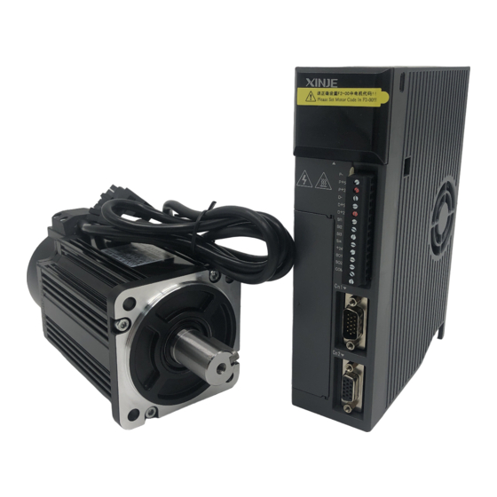
- Page 1 DS2 series servo drive User manual Xinje Electronic Co., Ltd. Serial No. SC02 20101119 1.0...
- Page 2 All copyrights reserved by Xinje Electronic Co., Ltd. Any copying, transferring or any other usage is pro hibited. Otherwise Xinje will have the right to pursue legal responsibilities. All rights including patent and pemission of modules and designs are reserved.
- Page 3 Safety Precautions Be sure to review this section carefully before use this product. In precondition of security, wire the product correctly. The following defines the symbols used in this manual to indicate varying degrees of safety precautions and to identify the corresponding level of hazard inherent to each. Failure to follow precautions provided in this manual can result in serious, possibly even fatal, injury, and/or damage to the persons, products, or related equipment and systems.
- Page 4 CAUTION 1. Do not connect a three-phase power supply to the U, V, or W output terminals. Doing so may result in injury or fire. 2. Use 2mm wire to grounding the groud terminals. Not doing so may result in electric shock. 3.
-
Page 5: Table Of Contents
Catalog Preface..........................I 1 Checking Product and Part Names ................2 1-1.Checking Products on Delivery ...............2 1-1-1. Servomotors ...................2 1-1-2.Servo Drivers ..................3 1-1-3.Adaptation table of servo drive and motor ..........4 1-2.Product Part Names ..................4 1-2-1.Servomotors ..................4 1-2-2.Servo Drivers ..................5 2-1.Servomotor .....................7 2-1-1.Storage Temperature ................7 2-1-2.Installation Site ..................7 2-1-3.Concentricity ..................7... - Page 6 4-2.Running status mode ..................25 4-3.Monitoring Mode ..................26 4-4.Auxiliary Function ..................28 4-4-1.Check System Infomation ..............29 4-4-2. Auxiliary Run Mode ................29 4-4-3. Change the motor type ................. 30 4-4-4.Check Alarm Information ..............31 4-4-5.Reset Parameters to Default ............... 31 4-4-6.
- Page 7 5-5-7-2. External torque limit (via input signal) ..........52 5-5-7-3. External torque limit (via analog voltage command) ......53 5-5-7-4. External torque limit (via external input + analog voltage) ....53 5-5-7-5. Output torque up to limit value signal ..........54 5-5-8.
- Page 8 7 Specification and dimension ..................69 7-1.Servo motor ....................69 7-1-1.Servo motor specification ..............69 7-1-2.Torque-Speed Feature ................ 71 7-1-3.Servo motor dimensions ..............72 7-2.Servo drivers ....................75 7-2-1.General specification ................75 7-2-2.Performance specification ..............76 7-2-3.Servo driver dimensions ..............77 8 Alarm Information ......................
-
Page 10: Preface
This chapter describes precautions for servomotor and servo driver installation. 3. Wiring This chapter describes the procedure used to connect DS2 Series products to peripheral devices and gives typical examples of main circuit wiring as well as I/O signal connections. -
Page 11: Checking Product And Part Names
Check the motor code marked on the nameplates of the code in driver? servomotor and the parameter F0-00 on the servo driver. If any of the above is faulty or incorrect, contact Xinje or an authorized distributor. 1-1-1. Servomotors External Appearance ... -
Page 12: Servo Drivers
First 3 bits mean rated torque, last 2 bits mean rated speed Performance Such as: 00630: rated torque 0.6N.m, rated speed 3000rpm parameter no. 06025: rated torque 6.0N.m, rated speed 2500rpm 19015: rated torque 19.0N.m, rated speed 1500rpm No bond Shaft spec With bond Vacant... -
Page 13: Adaptation Table Of Servo Drive And Motor
2.3KW 3.0KW 220V Voltage level 380V 1-1-3.Adaptation table of servo drive and motor Motor type Motor code Suitable drive Voltage level DS2-20P2 1-phase 220V MS-60ST-M00630-20P2 0003 DS2-20P2-A 3-phase 220V DS2-20P4 1-phase 220V MS-60ST-M01330-20P4 0004 DS2-20P4-A 3-phase 220V DS2-20P7 1-phase 220V MS-80ST-M02430-20P7 0011 DS2-20P7-A... -
Page 14: Servo Drivers
1-2-2.Servo Drivers DS2-20P2, DS2-20P4, DS2-20P7 COM1 5-pin port, for RS232 communication POWER LED Turn on when the drive power on CHARGE LED Turn on when main circuit power on. Do not touch the servo when LED is ON after power off because there are charges in the capacitance. Panel display Show the servo state, alarm and parameters Panel keys... - Page 15 DS2-2□P□-A, DS2-2□P□-B POWER LED Turn on when the drive power on Panel display POWER CHARGE CHARGE LED To show the servo state, alarm, parameters STA/ESC ENTER Turn on when main circuit power on. Panel keys Do not touch the servo when LED is To set the parameters PUL- ON after power off because there are...
-
Page 16: Servomotor
Installations This chapter describes precautions for servomotor and servo driver installation. 2-1.Servomotor MS series servomotors can be installed either horizontally or vertically. The service life of the servomotor can be shortened or unexpected problems might occur if it is installed incorrectly or in an inappropriate location. -
Page 17: Orientation
0.2 to 0.3mm 2-2.Servo Drivers The DS2 series servo drivers are base-mounted servo drivers. Incorrect installation will cause problems. Follow the installation instructions below 2-2-1.Storage Conditions ℃... -
Page 18: Orientation
subject to excessive dust or iron powder in the air. 2-2-3.Orientation Install the servo driver perpendicular to the wall as shown in the figure. The servo driver must be oriented this way because it is designed to be cooled by natural convection or by a cooling fan. - Page 19 When install servo drivers side by side as shown in the figure above, make at least 10mm between and at least 50mm above and below each servo driver. Install cooling fans above the servo drivers to avoid excessive temperature rise and to maintain even temperature inside the control panel.
-
Page 20: Wiring
I/O signal connections. 3-1.Main Circuit Wiring This section shows typical examples of main circuit wiring for DS2 Series servo products, functions of main circuit terminals, and the power ON sequence. Observe the following precautions when wiring. -
Page 21: Typical Wiring Example
DS2-21P5 Terminal Function Explanation Suppress current high 1 and 2 is short when out of factory. harmonics, to connect Connect DC reactor between 1 and DC reactor 2 to suppress current high harmonics. L, N Power input of main Single-phase AC 200~240V, 50/60Hz circuit Ground... -
Page 22: Winding Terminals On Servo Motor
3-1-3.Winding Terminals on Servo motor Symbol 60, 80, 90 Series 110, 130, 180 Series 3-2.I/O Signals This section describes I/O signals for the DS2 series servo driver. 3-2-1.Layout of CN0/CN1 Terminals The diagram shows the solder side: DS2-20P2 DS2-2□P□-A DS2-20P4 DS2-21P5 DS2-2□P□-B... - Page 23 Pulse B, pulse signal Input terminal 3 +24V for pulse terminal Input terminal 4 Input terminal 1 +24V +24V for input DS2-2□P□-A DS2-2□P□-B Name Description Name Description PUL- Pulse input PUL- Input terminal 1 Differential input PUL+ Input terminal 2 PUL+ +24V for open +24V...
-
Page 24: I/O Signal Names And Functions
3-2-3.I/O Signal Names and Functions The following section describes servo driver I/O signal names and functions. Input Signals Item Input Function Reference chapter Digital input Multi-functional input terminal 5-12-1 SI1~SI6 P2-00=1:A-phase pulse PUL- 5-3-2 P2-00=2:pulse PUL+ Pulse input P2-00=1:B-phase pulse DIR- 5-3-2 P2-00=2:pusle direction (sign) - Page 25 DS2-20P2 Open collector output ( power supply is 24V) DS2-20P4 Host device servo drive DS2-20P7 PULS +24V DS2-21P5 +24V R=2.2K Ω SIGN COM0 COM1 R=2.2KΩ Shield layer DS2-2□P□-A Open collector output (power supply is 24V) DS2-2□P□-B Host device servo drive +24 V PUL-...
-
Page 26: Wiring Encoders
The interface with the input circuit Use relay or open collector transistor circuit to connect. Please choose micro-current relay when using relay. Otherwise, the contact will be not good. Open collector output (24V power supply) Relay output (24V power supply) Host device servo drive Host device... -
Page 27: Cn2 Encoder Connector Terminal Layout
Incremental encoder servo unit host device ( DB15 ) 8 AO 9 BO 10 ZO 13 GND Shield cables SHIELD Connector shell (shell) Shield calbes Means twisted wire shield cables 3-3-2.CN2 Encoder Connector Terminal Layout CN2 Connector Terminal Layout The following diagrams are the layout of CN2 connector (face the solder pin). -
Page 28: Position Control Mode
Besides, the control signal wires must connect to the ground, the ground method is shown as below: The shield method of control signal wires: PUL- PUL+ Host device Servo DIR- DIR+ +24V *single-ground the shield layer 3-4-1.Position Control Mode DS2-20P2, DS2-20P4 and DS2-20P7 Single phase AC 220V (50/60Hz) Regenerative resistor... - Page 29 DS2-21P5 single-phase AC220V (50/60Hz) be sure to properly regenerative operate the end of the resistor shield wire /PUL 3.3KΩ Shield layer /SIGN positioning connects to 0V at completed signal side, COIN vacant at drive side +24VIN user defined alarm output /S-ON 3.3KΩ...
-
Page 30: Communication Port
DS2-2□P□-A、DS2-2□P□-B 3-phase 220V AC (50/60Hz) Regenerative resistor Well operate with the shield wire CN1-10 CN0-1 /PUL CN1-9 Shield layer 2.2KΩ connects to 0V CN0-4 /DIR Encoder at signal side, CN1-8 signal vacant CN0-3 output drive side CN1-13 +24VIN 3.3K Ω CN0-9 /S-ON Servo enable ON... -
Page 31: Serial Port 2(Com2)
Note: 1, Please use the cable provided by Xinje company. 2, the types in the table cannot use RS232 (COM1) and RS485 (COM2) at the same time. The communication parameters of COM1 and COM2 will be changed at the same time. - Page 32 regenerative power needs to be reduced by the regenerative resistor. The servomotor is driven in regeneration (generator) mode in the following conditions: While decelerating to a stop during acceleration/deceleration operation. With a load on the vertical axis. During continuous operation with the servomotor driven from the load side (negative load).
-
Page 33: Use The Operate Panel
Use the operate panel This chapter describes the basic operation of the operate panel and the features it offers. All parameter settings and motor operations can be executed by simple, convenient operations. 4-1.Basic Operation This section provides information on the basic operation of the operate panel for setting operating conditions. -
Page 34: Running Status Mode
Power ON Running status Parameter setting Monitoring Auxiliary function Display mode: Monitor Function U- XX: XX means the number of the monitor function. Auxiliary Function FX-XX: The first X means group No., the last two X means the member No. -
Page 35: Monitoring Mode
(/TGON) Rotation Detection Speed Level: P5-02(Unit: rpm) Zero Clamp (/ZCLAMP) Light when zero clamp signal is ON. Light when actual speed exceeds preset value. Speed Limit (/VLT) Speed Limit during Torque Control: P4-07 B. The code contents: Code Descrption Standby Servo OFF (motor power OFF) Servo ON (motor power ON) Forward Run Prohibited... - Page 36 Using the Monitor Mode Now we take the monitor code U-16 as an example. 1. Press the STATUS/ESC key to select the monitoring mode. 2. Press the INC or DEC key to select the monitor number U-16, and then press and hold ENTER to enter the monitor mode.
-
Page 37: Auxiliary Function
LED4_1 /SPD-B internal set speed selection LED5_1 /P-CON proportion action command LED4_2 /C-SEL control mode selection LED5_2 /P-OT forward prohibit LED4_3 /ZCLAMP zero clamp LED5_3 /N-OT reverse prohibit LED4_4 /INHIBIT prohibit pulse command LED5_4 /ALM-RST clear the alarm /P-CL external torque limit at LED4_5 /G-SEL switch the gain LED5_5... -
Page 38: Check System Infomation
4-4-1.Check System Infomation Press STATUS/ESC to switch to the auxiliary function mode. Set the group No. to 0 to check system information. Press INC or DEC key to select different No., and press and hold ENTER key to check current information. Press STATUS/ESC key to return. The following table describes the meaning of each No. -
Page 39: Change The Motor Type
If correctly wired, the motor would rotate in 5 seconds in forward direction (fixed to counter-clockwise), otherwise the motor would shock or viberate, raising an alarm for worse. In this case the power must be switched off immedietely and check the wiring again. -
Page 40: Check Alarm Information
5. Repower on the servo drive to make this function effective. 4-4-4.Check Alarm Information Set group No. to 2 in auxiliary function mode and enter checking alarm information mode. The following steps show how to check alarm information. 1. Press STATUS/ESC key to select Auxiliary Function mode. 2. -
Page 41: Alarm
The example below shows how to change parameter P3-09 from 2000 to 3000. 1. Press the STATUS/ESC key to select the parameter setting mode. 2. At this time the second LED is blinking, and press INC or DEC key to set the group No. to 3. -
Page 42: Run The Servo System
This chapter describes the basic function and using method of DS2 series servo. 5-1.Control mode selection DS2 series servo has one main mode and two sub modes. Sub mode 1 and 2 can be switched to each other via /C-SEL signal. -
Page 43: Servo On Setting
5-2-1. Servo ON setting When servo ON signal is ineffective, the servo motor cannot run. Parameter Signal Setting Explanation Change Effective P5-10 /S-0N n.0001 When SI1 is ON, servo motor Repower (default powers on and enables to run. value) n.0010 Always effective, no need to wiring. - Page 44 (2) Set the overtravel signal Parameter Signal Setting Explanation Modify Effective P5-12 /P-OT n.0013 SI3=ON, prohibit the forward running Repower on n.0003 SI3=OFF,prohibit the forward running (default value) n.0010 Always prohibit the forward running n.0000 Do not use forward overtravel signal P5-13 /N-OT Default value is n.0004, input signal from SI4...
-
Page 45: Motor Stop Mode When Servo Off
P0-06.L range Explanation Inertia stops. After stop, keep on inertia motion state. Notes: DS2 series servo drive doesn’t have built-in DB brake. So no matter what value P0-06.L is, servo will keep on inertia motion after stop. 5-2-5. Power-off Brake (BK) It is used when servo drive controls the vertical shaft. - Page 46 Servo motor with brake Servo drive Power L1 L2 BK-RY +24V Power supply for brake BK-RY Note: the working voltage of brake is DC 24V, current is about 0.6A. In above diagram, BK signal is output from SO1, set parameter P5-34 to n.0011. (2) Brake signal The signal controls the brake.
-
Page 47: Position Mode (External Pulse Command)
parameter P5-06 to delay the servo OFF, make sure the servo isn’t OFF until the brake action in order to delete the machine moving. Note: this parameter is the time when motor stop and TGON is invalid. (4) Brake ON parameter (When servo motor is rotating) The brake action setting during the motor is rotating: parameter P5-07, P5-08. -
Page 48: Control Mode Selection
Effective value mode P2-00 CW, CCW mode 6, 7 Servo Re-power Pulse+direction Note: DS2 series (hardware version 3.2) cannot support AB phase pulse. 5-3-2-2. Explanation of command pulse Command pulse mode Electrical specification Remark Direction+pulse (DIR+PUL signal) Direction (DIR) τ... -
Page 49: Signal Connection
5-3-2-3. Signal connection The signal connection please refer to chapter 3-2-4. 5-3-3. Electronic gear ratio The electronic gear function is set any value for motor moving quantity corresponding to input pulse command. The host device which sends command doesn’t need to consider the machine deceleration ratio and encoder pulse quantity. -
Page 50: Example Of Setting The Electronic Gear
Calculate the moving Calculate the actual unit value the load shaft rotates 1 circle value the load shaft based on reference unit rotates 1 circle Calculate the electronic Calculate the electronic gear ratio based on the formula (B/A) gear ratio Set the parameters Set the result as the electronic gear ratio 1. -
Page 51: Pulse Error Clear (/Clr)
Select 1-time delay feature or moving average filter. P2-01 Content First-order inertia filter Smooth filter Set the filter time: P2-04 Position command filter time parameters Unit Default Range Suitable mode Modify Effective 0~100 6, 7 Servo OFF Re-power on Addition: The comparison of P2-04 in First-order inertia filter and smooth filter mode: First-order inertia filter Smooth filter... -
Page 52: Positioning Near (/Near)
Unit Default Range Suitable mode Modify Effective 1 reference unit 0~250 5, 6 Servo OFF Immediately Function: when the pulse error value is lower than P5-00, output /COIN signal. Monitor the pulse error value via U-08. Error 偏移脉冲 pulse (U-08) P5-00 (U-08) /COIN... -
Page 53: Position Mode (Internal Position Mode)
Input signal setting: Parameter Signal Default Meaning Suitable Modify Effective mode P5-22 /INHIBIT n.0000 Need to distribute 5, 6 Re-power Note: /INHIBIT can be input from input terminal by setting P5-22. Please refer to chapter 5-12-1 5-4.Position mode (internal position mode) Parameter Parameter Name... - Page 54 n.xxx□ Positioning mode Mode explanation: (1) Wait mode n.x□xx Meaning Wait for the completion of positioning Not wait for the completion of positioning Notes: the wait mode means wether the drive waiting for the completion of positioning in internal position setting mode. This is effective in any change step mode. Wait mode = 0, adjust time = 0ms Wait mode = 0, adjust time >...
- Page 55 t1=P2-14, t2=P2-19 1. If /CHGSTP is ON, servo will run segment 1 and 2. 2. If /CHGSTP is OFF in one segment, servo will finish this segment and stop running the next segment. /CHGSTP Signal Change the step at the rising edge of the signal, single-step Suppose there are 2 segments.
-
Page 56: Position Parameters From Segment 1 To 16
5-4-3. Position parameters from segment 1 to 16 P2-5(n+1)+1 Pulse number (low bit) Suitable Unit Default Range Modify Effective mode 1 pulse -9999~9999 Servo OFF Immediately P2-5(n+1)+2 Pulse number (high bit) Suitable Unit Default Range Modify Effective mode 10000 -9999~9999 Servo OFF Immediately pulses... -
Page 57: Skip Current Signal (/Zclamp)
5-4-6. Skip current signal (/ZCLAMP) When /ZCLAMP signal is triggered in internal position mode, cancel the current stage running, enter the next stage as different conditions of change step mode. /Z-CLAMP signal Change step mode Execution Cancel current stage, execute the next stage at once Cancel current stage, execute the next stage when the change step signal is ON Cancel current stage, execute the next stage at once... - Page 58 Detailed explanation: Find reference origin diagram: /N-OT /P-OT Speed P2-95 Speed P2-95 ① Direction CW Direction CCW Stop mode Stop mode ② P0-06.H P0-06.H Speed P2-96 Speed P2-96 ③ Direction CW Direction CCW Z signal quantity Z signal quantity P2-94 P2-94 Reference origin Reference origin...
-
Page 59: Speed Control (Analog Voltage Command)
The reference origin defined by the two modes will be considered as the origin of absolute position control. 5-5.Speed control (analog voltage command) Note: only DS2-2□P□-A and DS2-2□P□-B support this mode. Basic parameters Parameter Name Reference P0-01 Select the control mode 5-5-1 P3-00 Analog value of rated speed... -
Page 60: Speed Command Offset Auto-Adjustment (F1-03)
5-5-3. Speed command offset auto-adjustment (F1-03) When the servo is in analog voltage speed mode, even if the command voltage is 0V, motor will run at very low speed. The micro-motion will happen when the command voltage micro-offset (mV) of host controller or external circuit occurs. Auto-adjust the command offset by operate panel of servo. -
Page 61: Speed Coincidence Checking (/V-Cmp)
5-5-6. Speed coincidence checking (/V-CMP) When motor speed is equal to the command speed, servo outputs speed coincidence signal (V-CMP). Parameter Signal Type Default Meaning Suitable mode Modify Effective P5-29 /V-CMP Output n.0000 Need to 3, 4, 7 Re-power on distribute Note: /V-CMP signal can be distributed to output terminal by parameter P5-29. -
Page 62: External Torque Limit (Via Analog Voltage Command)
Signal State Meaning Effective limit value /P-CL Forward external torque limit OFF P4-02 Forward external torque limit ON Min value between P4-02 and P4-04 /N-CL Reverse external torque limit OFF P4-03 Reverse external torque limit ON Min value between P4-03 and P4-05 5-5-7-3. -
Page 63: Output Torque Up To Limit Value Signal
/N-CL Reverse external torque P4-03 limit OFF Reverse external torque The min value among P4-03, P4-05 and analog voltage limit ON command 5-5-7-5. Output torque up to limit value signal The signal means the motor output torque reaches limit value. Parameter Signal Type... -
Page 64: Speed Command Input Dead Voltage
Unit Default Range Suitable mode Modify Effective 0.01ms 0~65535 3, 4, 5, 6, 7 Servo OFF Immediately Smooth filter the speed feedback. If set it too large, the speed feedback will distort and affect the control result. 5-5-10. Speed command input dead voltage P3-10 Speed command input dead voltage Unit... -
Page 65: Control Mode Selection
5-6-1. Control mode selection Parameter Set value Meaning Modify Effective P0-01 Speed control: internal speed selection Servo OFF Immediately Function: internal speed selection will set 3 motor speeds and select the speed by external signal. It is not need to configure external speed generator or pulse generator. Servo unit /SPD-D /SPD-A... -
Page 66: Speed Control (Pulse Frequency Command)
P3-03: SPEED3 Note: 1. SPEED1—SPEED2—SPEED3 switch as 01—11—10 but not 01—10—11. This can avoid the speed become zero at the space time of signal switching. 2. Please differ the signal state from terminal state. (2) Running example Speed 3 +SPEED3 Speed switching will... -
Page 67: Control Mode Selection
P4-05 Reverse external torque limit P5-15 Forward external torque limit /P-CL P5-16 Reverse external torque limit /N-CL P5-32 Torque up to limit value output /CLT Filter P3-08 Speed feedback filter time 5-5-9 5-7-1. Control mode selection Parameter Set value Meaning Modify Effective Speed control: pulse frequency speed... -
Page 68: Control Mode Selection
P5-10 Servo ON signal /S-ON 5-2-1 Other parameters Key words Parameter Name Reference Zero drift F1-04 Torque command offset auto-adjustment 5-8-3 adjustment Filter P4-01 Torque command filter time 5-8-4 Speed limit P4-07 internal speed limit in torque control mode 5-8-5 P3-09 Max speed control (MAX speed) P0-08... -
Page 69: Torque Limit
5-8-5. Torque limit 5-8-5-1. Internal speed limit Limit the speed of torque control by setting below parameters: P4-07 internal speed limit in torque control mode Unit Default Range Suitable mode Modify Effective 1rpm 2000 0~5000 1, 2 Servo OFF Immediately Note: the actual speed is max speed even this parameter speed is larger than the max speed. -
Page 70: Torque Control (Internal Setting)
5-9.Torque control (internal setting) Basic parameter Parameter Name Reference P0-01 Control mode selection 5-9-1 P5-10 Servo ON signal /S-ON 5-2-1 P4-09 Internal torque command 5-9-2 Other parameters Key words Parameter Name Reference Filter P4-01 Torque command filter time 5-8-4 Speed limit P4-07 Internal speed limit of torque control 5-8-5... -
Page 71: Other Output Signals
5-11.Other output signals 5-11-1. /ALM and /ALM-RST Servo alarm output /ALM Parameter Signal Type Default Meaning Effective P5-37 /ALM Output n.0002 Output always open signal from SO2 Re-power on 1. The servo unit is force OFF when alarming, the motor will move with external force (including gravity). -
Page 72: Encoder Z Phase Output (/Z)
SO1 signal 1ms~2ms Typical value1.5ms 5-11-6. AB phase feedback signal of encoder DS2-2□P□-A supports open collector output AB phase feedback signal. Please see the following wiring diagram of DS2-21P5-A and Xinje PLC XC3-32RT-E. Drive CN1(DB15) 8 AO 9 BO 13 GND AB phase feedback signal doesn’t have parameters to set;... -
Page 73: Default Setting Of Input Terminal
n.0010 Set the signal to be always valid n.001x Input always close signal Disconnect from SIx to 0V Connect to Note: if the distributed terminal has other signal, set the signal to other terminal or set to unused. The setting range of input terminal for each type: Input terminal parameter Servo type Range... -
Page 74: Output Terminal Distribution
5-12-3. Output terminal distribution Parameter meaning Set value Meaning Signal state Terminal state n.0000 Not distribute to n.00 y x terminal input 00: pointless n.000x Output always open Disconnect to COM y: 0 always open signal from S0x Connect to COM 1 always close n.0010 Set the signal to be... -
Page 75: Servo Gain Adjustment
Servo gain adjustment This chapter will introduce some skills about servo gain adjustment. 6-1.Servo gain setting 6-1-1.Gain setting of speed loop Gain parameters about speed loop: P1-00 Speed loop gain (Kp) Unit Default Range Suitable mode Modify Effective 1~5000 3, 4, 5, 6, 7 Immediately P1-01 Speed loop integral time constant (Ki) -
Page 76: Position Loop Feedforward Gain
The offset pulse will not be checked when offset pulse limit value is 0. (alarm E-10) U P5-05 Normal control Offset pulse 0 (alarm E-10) 6-1-2-2.Position loop feedforward gain P1-09 position loop feedforward gain (Kp) Unit Default Range Suitable mode Modify Effective 1~100... -
Page 77: Gain Switch (G-Sel)
Parameter Signal Type Default State Meaning Modify Effective P5-11 /P-CON Input n.0000 Run in P control mode Re-power Run in PI control mode /P-CON can be distributed to input terminal via parameter P5-11. Refer to chapter 5-12-1. This command is suitable for the following cases: (1) When the host device sends speed command to the servo and runs with it at the same time, it only selects P mode running under special conditions. -
Page 78: Specification And Dimension
Specification and dimension This chapter will introduce the specification and dimension of MS series servo motor and DS2 series servo drive. 7-1.Servo motor 7-1-1.Servo motor specification Please refer to this chapter when selecting the servo drive. Voltage level 220V 60ST-... - Page 79 Max speed(rpm) 3000 2000 2000 2000 Rated torque(N·m) Peak torque(N·m) Back EMF constat (V/krpm) (N·m/A) Torque coefficien 1.67 1.58 1.58 (Kg·m ) Rotor inertia 1.26×10 1.94×10 2.77×10 3.8×10 (Ω) Winding resistor 1.01 1.34 (mH) Winding inductance 2.94 5.07 4.45 2.42 (...
-
Page 80: Torque-Speed Feature
7-1-2.Torque-Speed Feature A: continuous use area B: repeated use area MS-60ST-M01330□□-20P4 MS-80ST-M02430□□-20P7 MS-90ST-M02430□□-20P7 MS-110ST-M04030□□-21P2 MS-110ST-M05030□□-21P5 MS-130ST-M06025□□-21P5 MS-130ST-M10015□□-21P5... -
Page 81: Servo Motor Dimensions
7-1-3.Servo motor dimensions Dimensions of 60 series servo motors (unit: mm) Type Normal Band-type brake MS-60ST-M00630□□-20P2 MS-60ST-M01330□□-20P4 Dimensions of 80 series servo motors (unit: mm) - Page 82 Type Normal Band-type brake MS-80ST-M02430□□-20P7 Dimensions of 90 series servo motors (unit: mm) Type Normal Band-type brake MS-90ST-M02430□□-20P7...
- Page 83 Dimensions of 110 series servo motors (unit: mm) Type Normal Band-type brake MS-110ST-M04030□□-21P2 MS-110ST-M05030□□-21P5 Dimensions of 130 series servo motors (unit: mm) Type Normal Band-type brake MS-130ST-M06025□□-21P5 MS-130ST-M10015□□-21P5 MS-130ST-M07725□□-22P0 MS-130ST-M15015□□-22P3...
-
Page 84: Servo Drivers
MS-180ST-M19015□□-23P0 7-2.Servo drivers This section introduces the specification and dimension of servo drive. 7-2-1.General specification Servo unit DS2 series 220V servo drive Encoder Incremental encoder (2500 ppr) DS2-2□P□: single phase AC200~240V, 50/60Hz Input power DS2-2□P□-A: 3-phase AC200~240V, 50/60Hz DS2-2□P□-B: 3-phase AC200~240V, 50/60Hz... -
Page 85: Performance Specification
7-2-2.Performance specification DS2-20P4 Servo drive type DS2-20P2 DS2-21P5 DS2-2□P□-A DS2-2□P□-B DS2-20P7 Speed control range 1: 4000 (the lower limit of speed control range, not stop at rated load torque) Load change 0~100% load: below ±0.01% (rated speed) rate Speed Voltage change change Rated voltage ±10% : 0% (rated speed) rate... -
Page 86: Servo Driver Dimensions
7-2-3.Servo driver dimensions DS2-20P2, DS2-20P4, DS2-20P7 (unit:mm) 137.0 50.0 137±0.03 2-Φ5.0 DS2-21P5 (unit:mm) 180,5 POWER CHARGE STA/ESC INC ENTER... - Page 87 DS2-2□P□-A, DS2-2□P□-B (unit:mm) POWER CHARGE STA/ESC ENTER PUL- PUL+ DIR- DIR+ +24V...
-
Page 88: Alarm Information
Alarm Information This chapter describes the alarm information of DS2 series servo drivers. Alarm Code Description Reason Solution Re-download the program or E-001 Program damage program self-test failed contact Xinje or an authorized distributor Restart the drive to reset the Parameter self-test parameters. - Page 89 Motor code cannot E-031 Motor code error Set the motor code in F2-00 again match to drive type System chip is Contact Xinje or an authorized E-032 Initialization error damaged distributor...
-
Page 90: Appendix 1 Parameter List
● 5-2-2 06.L: stop mode when servo OFF or alarm. ● 5-2-4 0~2 DS2 series default is inertia stop. Keep the inertia motion after stop. 06.H: over range (OT) stop mode ● 5-2-3 0~3 0~1: inertia stop. Keep inertia motion after stop. - Page 91 P1: control parameters Modbus address: 0100~01FF Name Unit Default Range Effective Chapter The gain of speed loop √ 6-1-1 1~5000 Speed loop integral time 0.1ms √ 6-1-1 1~50000 The gain of position loop √ 6-1-2 1~2000 Reserved The gain of second speed loop √...
- Page 92 P3: speed control Modbus address: 0300~03FF Name Unit Default Range Effective Chapter Analog value of rated 0.01V 1000 ○ 5-5-2 150~3000 speed Internal setting speed 1 √ 5-6-2 -5000~+5000 Internal setting speed 2 √ 5-6-2 -5000~+5000 Internal setting speed 3 √...
- Page 93 Input filter time 0~100 √ ※ 1 ※ 3 - /S-ON servo signal ● 5-2-1 0000: signal is always ineffective 0001: input positive signal to SI1 0002: input positive signal to SI2 0003: input positive signal to SI3 0004: input positive signal to SI4 0005: input positive signal to SI5 0006: input positive signal to SI6 0010: signal is always effective...
- Page 94 ditto ※ 2 ※ 4 - /S-RDY ready ● 5-11-4 ditto ※ 2 ※ 4 - /CLT torque limit ● 5-5-7-5 ditto ※ 2 ※ 4 - /VLT speed limit checking ● 5-8-5-3 ditto ※ 2 ※ 4 - /BK brake lock ●...
- Page 95 Internal torque command 0x0702 Alarm/warn code 1 0x0718 Rotation angle (physical angle) 0x0703 U phase current when alarming 0x0719 Rotation angle (electricity angle) 0x0704 V phase current when alarming 0x071A Bus voltage 0x0705 DC bus voltage when alarming 0x071B Module temperature 0x0706 IGBT temperature when alarming 0x071C...
-
Page 96: Appendix 2 Application
Appendix 2 Application Mode 6: pulse command position mode Equipment introduction: This is a welder. Workpiece 1, 2, 3 are the object to be operated. 2 and 3 is fixed on B and A individually. A and B can whole move and be pushed by ball screw E and F. The screw pitch is 5mm. C and D is servo motor. - Page 97 Calculate the electronic gear ratio 2500 4 40 5000 Set the user parameters P2-02=80 P2-03=1 Parameter setting Running mode: P0-01=6 Pulse command state: P2-00=2 Electronic gear ratio: P2-02=80 P2-03=1 Forward torque limit: P4-02=150 Reverse torque limit: P4-03=150 Positioning finished width: P5-00=7 /S-ON: P5-10=0010 /CLR: P5-24=0001...
- Page 98 Xinje Electronic Co., Ltd. 4th Floor Building 7,Originality Industry park, Liyuan Development Zone, Wuxi City, Jiangsu Province 214072 Tel: (510) 85166657 Fax: (510) 85111290 www.xinje.com...