Xinje DS2 Series Manual
380v servo drive
Hide thumbs
Also See for DS2 Series:
- Manual (71 pages) ,
- User manual (99 pages) ,
- User manual (98 pages)

Subscribe to Our Youtube Channel
Related Manuals for Xinje DS2 Series


Summary of Contents for Xinje DS2 Series
- Page 1 DS2 series 380V servo drive Fast manual WUXI XINJE ELECTRIC CO., LTD. Serial NO. SC2309 20150708 1.0...
-
Page 3: Safety Caution
►► Safety caution Confirmation when receive products DO NOT install any driver which is damaged, lack of accessories or not the same with the model ordered. Installation Cut off external power supply before installation. Wiring ... -
Page 4: Model Description
Is the motor code the same with the the servomotor and the parameter F0-00 on the servo code in driver? drive. If any of the above is faulty or incorrect, contact XINJE or an authorized distributor. 2. Model description 1)Servo drive DS2 – 45P5 – A... - Page 5 Base size: 180; Feedback component: M (Photoelectric pulse encoder) Performance Specifications: First 3 numbers mean rated torque, last 2 numbers mean rated revolution; For instance:35015: rated torque 35N· m,rated revolution 1500rpm; 48015: rated torque 48N· m, rated revolution 1500rpm; Shaft Specifications: A-Without key; B-With key; Power-loss brake: Null-Have it;...
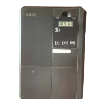
- Page 6 2)Servo drive POWER LED Turn on when the drive power on CHARGE LED POWER CHARGE Turn on when main circuit power on. Panel display Show the servo state, alarm and parameters Panel keys ENTER To set the parameters CN0/CN1/CN3 To connect the I/O signal and RS485 communication port To connect the encoder on the servo motor COM1 Connect to PC, HMI, PLC...
- Page 7 Back EMF constat(V/krpm) Torque coefficient(N· m/A) 2.26 3.37 2.70 2.92 ) Rotor inertia(Kg· m 4.7× 10 7.2× 10 6.1× 10 9.18× 10 8.6× 10 Winding resistor(Ω) 0.71 0.59 0.796 0.62 Winding inductance(mH) 4.00 14.4 4.83 15.1 4.00 Electrical time constant(ms) 5.63 24.4 6.07...
-
Page 8: Installations
(V/krpm) Torque coefficient (N· m/A) 2.40 ) Rotor inertia(Kg· m 9.5× 10 23.5× 10 Winding resistor(Ω) 0.273 0.46 Winding inductance(mH) 2.14 5.54 Electrical time constant 7.84 (ms) Weight(Kg) 40.0 Encoder ppr(PPR) 2500 Pole pairs Motor insulation level Class B (130℃) Protection level IP65 -20℃~+50℃... - Page 9 Store the servomotor within -20~+60 ℃ as long as it is stored with the power cable disconnected. 2) Installation Site Indoor,free of corrosive or explosive gases. Well-ventilated and free of dust and moisture. Ambient temperature of 0° to 50° C. ...
-
Page 10: Servo Drive
0.2 to 0.3mm 2. Servo drive The DS2 series servo drives are base-mounted servo drives. Incorrect installation will cause problems. Follow the installation instructions below. 1)Storage Conditions Store the servo drive within -20~+85℃, as long as it is stored with the power cable... - Page 11 3)Orientation Install the servo drive perpendicular to the wall as shown in the figure. The servo drive must be Wall oriented this way because it is designed to be cooled by natural convection or by a cooling fan. Ventilation 4) Installation Follow the procedure below to install multiple servo drives side by side in a control panel.
- Page 12 Side-by-side Installation When install servo drives side by side as shown in the figure above, make at least 10mm between and at least 50mm above and below each servo drive. Install cooling fans above the servo drives to avoid excessive temperature rise and to maintain even temperature inside the control panel.
- Page 13 Motor Model code Normal With brake 0156 MS-180ST-M19015□□-43P0 1052 MS-180ST-M21520□□-44P5 0150 2151 MS-180ST-M27015□□-44P3 0151 1152 MS-180ST-M35015□□-45P5 0152 MS-180ST-M48015□□-45P5 0153 220 Series(Units: mm) Motor Model code Normal With brake MS-220ST-M70015□□-411P0 1157...
- Page 14 2. Servo drive(Units: mm) DS2-45P5-A/AS POWER CHARGE ENTER...
- Page 15 DS2-47P5-A, DS2-411P0-A 120.0 CHARGE POWER ENTER WARNING ! * STORED CHARGE DO NOT TOUCH UNTIL 10 MIN. AFTER DISCONNECTION * DO NOT CONNECT AC POWER TO OUTPUT TERMINALS OF "U V W" * RISK OF ELECTRIC SHOCK-DUAL SUPPLY DISCONNECT MAINS AND LOADSHARING BEFORE SERVICE 160.0 230.0...
-
Page 16: Performance Specification
►► Servo drive general specification Servo unit DS2 series 380V servo drive Encoder Incremental encoder (2500 ppr) Input power DS2-4□P□-A/AS: 3-phase AC380V, 50/60Hz 3-phase full-wave rectifier control IPM PWM sine-wave Control mode current drive 0~+50 ℃/-20~+85 ℃ Temperature Humidity Below 90% RH (no condensation) - Page 17 Input signal RS485 Feedforward 0~100% (resolution is 1%) compensation Performance Positioning 0~250 command unit (resolution is 1 command finished width unit) Input Sign+ pulse, CW, CCW mode pulse type Input Collector (+24V) and differential signal input pulse state Input signal Input Open collector input: 200kHZ pulse...
- Page 18 Program error, parameter error, overvoltage, undervoltage, regeneration error, overtemperature, overcurrent, overspeed, analog input error, position Protection offset overflow, output shorting, current error, encoder cut, encoder error, overload, power off when running, write parameter error… Charge, power supply, 7-segment LED × 5 (built-in LED display digital operate) Connector...
- Page 19 ►► Wiring Names and Descriptions of Main Circuit Terminal 5.5KW driver: 7.5~11KW driver: Terminal names Function R、S、T 3-phase AC 380V± 10% (50/60Hz) P+、PB Regenerative braking resistor connection P+、P- Power supply for main circuit Ground Connect to the ground terminal of motor and power, to be grounded) U、V、W Motor connection...
- Page 20 P+5V +24V for open P+24V Input terminal 2 collector Direction input Input terminal 3 Differential input D+5V +24V +24V for input D+5V Terminals description of CN1 (1) DS2-45P5/47P5-A, DS2-411P0-A Name Description Name Description Null Encoder output B Input terminal 4 Encoder output Z Input terminal 5 T-REF...
-
Page 21: I/O Signal Names And Functions
Input terminal 5 T-REF Torque analog input Null V-REF Speed analog input analog +24V +24V for input input Output terminal 3 Encoder output B- Ground of output Encoder output B+ terminal Encoder output Z- Terminals description of CN3 Name Description Name Description... -
Page 22: Communication Port
Shield 6. Communication port Serial Port 1(COM1) COM1 supports RS232, and is often used to connect with PC for debugging. Name Description RS232 send RS232 receive (5-pin port) RS232 ground Caution:1. Please use the cable provided by XINJE company. - Page 23 2. The types in the table cannot use RS232 (COM1) and RS485 (COM2) at the same time. The communication parameters of COM1 and COM2 will be changed at the same time. Serial Port(COM2) (Pin: A:CN3-4, B:CN3-5) Communication parameters of COM2 can be set via P0-04. Parameter Name Default Setting...
-
Page 24: Regenerative Resistor
Number - P0-03 Modbus Station Number 1~255 Note: Parameters above will take effect after repower on. 7. Regenerative resistor Servo drive Built-in External regenerative resistor model regenerative resistor External regenerative resistor is 20Ω, 2000W and up. Connect it between P+ and PB. The resistor in the DS2-45P5-A/AS packing box has no positive and negative for wiring. - Page 25 8. Standard connection example of DS2-45P5-A/AS, DS2-47P5-A, DS2-411P0-A 3-phase 380V (50/60HZ) Regenerative resistor The shield layer PUL- CN0-1 150Ω connect 0V at signal side, CN0-2 Well operate with connect CN0-3 the end of shield 3.3KΩ nothing at servo cable side CN1-10 DIR- CN0-4...
-
Page 26: Using The Operation Panel
Note: This is the standard connection diagram when pulse signal is open collector input (+24V). ►► Using the operation panel 1. Basic operation The operate panel can be used for parameter settings, operating references, and status displays. 5-bit LED displays parameter settings, status or alarm. POWER CHARGE Button name... - Page 27 Display mode: Status: bb stand for the servo system is in idle status; run stand for the servo system is in run status Parameter settings mode PX-XX: the first X is group code; the second X is parameter code in this group. Auxiliary function mode: FX-XX: the first X is group code;...
-
Page 28: Running Status
2. Running status Speed, torque control mode Speed consistent V-CMP Torque limit CLT Rotation detection TGON Zero clamp ZCLAMP Speed limit VLT A. Bit display Bit data contents When motor’s actual speed is the same as the order P5-29 speed, the light on. - Page 29 Torque control speed limit: P4-07 Code contents Code Contents Standby Servo is OFF (motor has no electricity) Servo enable (motor has electricity) Forward prohibit P-OT ON Reverse prohibit N-OT ON Position control Positioning end COIN Near NEAR Rotation detection TGON A.
- Page 30 For position control, when given position is the same to P5-36 actual, the light on Near (/NEAR) Near signal width: P5-04 P5-30 When motor speed is higher than the rotation detection Rotation detection speed, the light on (/TGON) Rotation defection speed∶ P5-02 (Unit: rpm) Code display Code Contents...
-
Page 31: I/O Signal Status
U-07 Input command pulse speed (0000~9999)*1 U-08 Offset command Command (0000~9999)*10000 pulse value pulse U-09 (0000~9999)*1 U-10 Rotate angle (encoder Encoder (0000~9999)*10000 value) pulse U-11 (0000~9999)*1 U-12 Input command Command (0000~9999)*10000 pulses pulse U-13 (0000~9999)*1 U-14 Feedback command Command (0000~9999)*10000 pulses pulse U-15... - Page 32 Input signal distribution segment instruction segment instruction LED4_0 /SPD-A set internal speed LED5_0 /S-ON servo signal LED4_1 /SPD-B set internal speed LED5_1 /P-CON ratio action command /C-SEL control mode LED4_2 LED5_2 /P-OT ban positive rotation selection LED4_3 /ZCLAMP zero clamp LED5_3 /N-OT ban reverse rotation /P-CL external torque limit at...
-
Page 33: Auxiliary Function
U-22 I/O terminal status LED1 LED2 LED4 LED5 Fig 1 Fig 2 In fig1, input terminal status is shown in LED5; output terminal status is shown in LED2. Fig 2 is the LED segment number. Input terminal Output terminal Segment Instruction Segment... - Page 34 F0-XX Code Contents Code Contents F0-00 Motor code F0-01 Series F0-02 Machine type F0-03 Production: year F0-04 Production date: month F0-05 Production date: day F0-06 Software version F0-07 Hardware version F1-XX Note: make sure the motor code in F2-00 is same to the one on the motor label before using, otherwise servo cannot work fine if motor code is not matched.
- Page 35 (2) test run(F1-01) Make sure the motor doesn’t connect to the machine before test running! Please enter test run if servo connects to non-original encoder line and power line. Set panel to F1-01, keep press ENTER to go to test run. The display will show the following when test running.
- Page 36 (6) forced enable ( F1-05) 0: cancel enable, return to bb status 1: forced enable, servo is in RUN status Power on again, forced enable will be ineffective Change the motor code (parameter F2-00) Note: Servo drive can match to different motors with similar power level. Please see the motor code on the product label.
- Page 37 F3-13 Alarm/warn code 4 when alarming F3-14 Alarm/warn code 5 when alarming F3-15 Alarm/warn code 6 when alarming F3-16 Alarm/warn code 7 when alarming ※1: when F3-00=0, no alarm ※2: when F3-01=0, no warning Set to default value (parameter F4-XX) F4-00=1,all parameter will back to default value.
-
Page 38: Parameter List
(2) The second LED will blink, press INC or DEC to change the value to 3, keep press ENTER to confirm. (3) The last two LEDs will blink at this time, press INC or DEC to change the value to 09, keep press ENTER to confirm. - Page 39 1:From the side view of motor load, CW is forward rotate ● 06.L: stop mode when servo OFF or alarm. 0~2 DS2 series default is inertia stop. Keep the inertia motion after stop. ● 06.H: over range (OT) stop mode 0~3 0~1: inertia stop.
- Page 40 3: deceleration stop. Change to inertia motion after stop. Torque: P4-06 urgent stop torque. ○ T-REF distribution 0~3 0: undefined. 1: make T-REF as external torque limit input 2: undefined. 3: when P-CL, N-CL is ON, make T-REF as external torque limit input. ○...
- Page 41 Reserved Reserved √ gain position loop 0~100 feedforward √ Feedforward filter time 0.01ms 0~65535 ~ 3. P2: position control(0200 02FF) Function Unit Default Range Effective ● Command pulse state 0,1,2 0:Symbol+ Pulse train 1:AB phase pulse(90° phase, 4-time mode) 2:Pulse+ direction ●...
- Page 42 ○ First segment adjustment time 0~65535 ○ First segment command filter time 0.1ms 0~65535 P2-16~P2-90 are 2~16 segments parameter setting. ● 94. Find the original point xx□x 0: invalid 1: valid ~ ● The signal quantity pass the Z phase xxx□...
- Page 43 ~ 5. P4: torque control(0400 04FF) Name Unit Default Range Effective ○ Analog value of rated torque 0.01V 1000 150~3000 ○ Torque command filter time 0.01ms 0~65535 √ Forward torque limit 0~300 √ Reverse torque limit 0~300 √ Forward external torque limit 0~300 √...
- Page 44 pulse ○ 256* Offset pulse limit value 1000 0~65535 command pulse ○ Servo OFF delay time (brake 0~500 command) ○ Brake command output speed 0~5000 ○ Brake command wait time 10~1000 √ Input filter time 0~100 ● - /S-ON servo signal 0001 0000-0016 0000: signal is always ineffective...
- Page 45 ● - /N-OT reverse drive prohibition 0004 0000-0016 ditto ● - /ALM-RST alarm reset 0002 0000-0016 ditto ● - /P-CL forward external torque 0000 0000-0016 limit ditto ● - /N-CL reverse external torque limit 0000 0000-0016 ditto ● - /SPD-D internal speed selection 0000 0000-0016 ditto...
- Page 46 ditto Reserved Reserved ● - /COIN positioning finished 0001 0000-0013 0000: not output to the terminal 0001: output positive signal from 0002: output positive signal from 0003: output positive signal from 0011: output negative signal from 0012: output negative signal from 0013: output negative signal from ●...
-
Page 47: Modbus Address
ditto - ● /WARN warn 0000 0000-0013 ditto ● - /NEAR near 0000 0000-0013 ditto ● - /ALM alarm 0002 0000-0013 ditto ● - /Z encoder Z signal 0000 0000-0013 ditto Note: P5-10~P5-25, P5-28~P5-38 SI/SO terminal cannot be repeated, otherwise, SI/SO function will lose efficacy. - Page 48 P0-10 0x000A P1-10 0x010A Parameter Modbus Modbus Parameter Modbus Modbus Address Address Address (hex) Address (hex) (decimal) (decimal) P2-00 0x0200 P3-00 0x0300 P2-01 0x0201 P3-01 0x0301 P2-02 0x0202 P3-02 0x0302 P2-03 0x0203 P3-03 0x0303 P2-04 0x0204 P3-04 0x0304 P2-05 0x0205 P3-05 0x0305 P2-06...
- Page 49 P4-05 0x0405 1029 P5-05 0x0505 1285 P4-06 0x0406 1030 P5-06 0x0506 1286 P4-07 0x0407 1031 P5-07 0x0507 1287 P4-08 0x0408 1032 P5-08 0x0508 1288 P4-09 0x0409 1033 P5-09 0x0509 1289 P4-10 0x040A 1034 P5-10 0x050A 1290 P4-11 0x040B 1035 P5-11 0x050B 1291 P4-12...
- Page 50 Monitor state address Modbus Modbus Modbus Modbus Explanations Address Address Explanations address Address (hex) (decimal) (hex) (decimal) U-00 Motor F3-00 current 0x0700 1792 0x0716 1814 speed alarm code U-01 Speed F3-01 Current 0x0701 1793 0x0717 1815 command warn code F3-02 U-02 Internal...
- Page 51 16 bits) when alarming U-09 Offset F3-09 V-REF pulse value 0x0709 1801 value when 0x071F 1823 (high 16 bits) alarming U-10 Rotation F3-10 T-REF angle (low 16 0x070A 1802 value when 0x0720 1824 bits) alarming U-11 Rotation F3-11 angle (high 16 0x070B 1803 Alarm/warn...
- Page 52 position (high 16 bits) U-18 Present 0x0712 1810 current U-19 Analog 0x0713 1811 input (speed) U-20 Analog 0x0714 1812 input (torque) Input signal state (can read and write) Address Address Address Address Explanation Explanation (hex) (decimal) (hex) (decimal) /SPD-A internal /S-ON servo signal 0x0800 2048...
- Page 53 limit /SPD-D internal /CHGSTP 0x0807 2055 0x080F 2063 speed selection change step Note: for example, /S-ON signal address 0x0800=1, this function is effective; 0x0800=0, this function is ineffective. Output state signal (can read, cannot write) Address Address Address Address Explanation Explanation (hex)
-
Page 54: Alarm Information
Description Reason Solution Code E-001 Re-download the program or Program program self-test failed contact XINJE or an authorized damage distributor E-002 Restart the drive to reset the parameters. If it occurs for Parameter Parameter self-test failed many times please contact... - Page 55 E-008 Motor speed is too fast, Check if there is other device Over speed motor UVW connection is that make motor revolve too error fast; check the UVW wiring. E-009 Input voltage error when Analog input Input correct voltage when zero 2-channe analog zero error calibration for analog...
- Page 56 Motor code cannot match to Set the motor code in F2-00 E-031 error drive type again Initialization Contact XINJE or an authorized E-032 System chip is damaged error distributor ►►Debug steps Please check the products before power on, make sure the devices are not significant damage.
-
Page 57: Motor Code
►►Motor code Rotate Capacity Torque Current Over Motor Motor Type speed load code MS-180ST-M21520 21.5 2000 0150 MS-180ST-M27015 1500 0151/2151 MS-180ST-M35015 1500 0152/1152 MS-180ST-M48015 1500 0153 MS-220ST-M70015B 11.0 1500 1157 ►► Suitable motor code for each servo drive Drive model Support code DS2-45P5-A/AS 0150... - Page 59 WUXI XINJE ELECTRIC CO., LTD. 4th Floor, Building 7th, No.100 Dicui Rd, Wuxi, China Tel: 86-0510-85134139 Fax: 86-0510-85111290 www.xinje.com...
Need help?
Do you have a question about the DS2 Series and is the answer not in the manual?
Questions and answers