
Related Manuals for Xinje DS2-20P7-AS


Summary of Contents for Xinje DS2-20P7-AS
- Page 1 DS2 series servo drive Manual Wuxi Xinje Electric Co., Ltd. Data No.: SC209 20110412 1.0...
- Page 3 ►► Safety notes Confirmation Do not use the drivers that are broken, lack of parts or wrong types. Installation Make sure all the external powers are cut off before install the drivers. Wiring Please cut off all the powers before wiring. ...
- Page 4 matched Please contact us if there are any problems in these items. 2. Type (1) Servo driver DS2 – 2 0P7 – AS Series name Configuration: AS DS2:compact model Motor capacity 0P2: 0.2KW Voltage level 0P4: 0.4KW 2: 220V 0P7: 0.75KW (2) Servo motor MS -80 ST - M 02430 A Z- 2 0P7 Power...
- Page 5 Shaft spec: A- no bond; B- with bond; Power-loss brake: empty- no brake; Z- with brake; Voltage level: 2-220V; Power: 0P2: 0.2KW; 0P4: 0.4KW; 0P7: 0.75KW; 3. Parts introduction (1) Servo motor Encoder Frame Flange Output shaft (2) Servo driver DS2-20P2-AS, DS2-20P4-AS, DS2-20P7-AS...
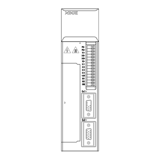
- Page 6 POWER Light when power on Panel display Display the servo state, parameter, alarm PUL- PUL+ DIR- DIR+ Panel buttons For parameter settings +24V Pulse, direction, I/O signal Power and motor terminal Drive and motor power terminal I/O, analog, position feedback signal Encoder terminal...
- Page 7 RS232 port Connect PC and HMI DIP switch Turn on 2, 3, and 5 for normal using ►► Installation 1. Servo motor MS series servo motors can be installed either horizontally or vertically. The service life of the servo motor can be shortened or unexpected problems might occur if it is installed incorrectly or in an inappropriate location.
- Page 8 (1) Storage temperature Store the servomotor within -20~+60 ℃ as long as it is stored with the power cable disconnected. (2) Installation location Free of corrosive or explosive gases. Well-ventilated and free of dust and moisture. Ambient temperature of 0° to 50°C. ...
- Page 9 MS series servo motors can be installed either horizontally or vertically. (5) Avoid oil and water Through part of the shaft Install a protective cover over the servomotor if it is used in a location that is subject to water or oil mist. Also use a servomotor with an oil seal when needed to seal the through-shaft section.
- Page 10 50°C. Installation Near a Minimize heat radiated from the heating unit as well as any Heating Unit temperature rise caused by natural convection so the temperature around the servo drivers does not exceed 50°C. Installation Near a Install a vibration isolator beneath the servo driver to avoid Source of Vibration subjecting it to vibration.
- Page 11 (4) Installation Follow the procedure below to install multiple servo drivers side by side in a control panel. PUL- PUL- PUL- PUL- PUL+ PUL+ PUL+ PUL+ DIR- DIR- DIR- DIR- DIR+ DIR+ DIR+ DIR+ +24V +24V +24V +24V Servo drive direction Install the servo driver perpendicular to the wall and make the front panel towards operator.
- Page 12 Ambient inside control panel Ambient Temperature: 0~50 ℃ Humidity: 90%RH or less Vibration: 4.9m/s Condensation and Freezing: None Ambient Temperature for Long-term Reliability: 50°C maximum ►► Dimensions 1. Servo motor 60 series motor installation dimensions Unit: mm ...
- Page 13 Type Normal With brake MS-60ST-M01330□□-20P4...
- Page 14 80 series motor installation dimensions Unit: mm Type Normal With brake MS-80ST-M02430□□-20P7...
- Page 15 MS-90ST-M02430□□-20P7 installation dimensions Unit: mm Type Normal With brake MS-90ST-M02430□□-20P7 2. Servo drive(unit: mm) DS2-20P2-AS, DS2-20P4-AS, DS2-20P7-AS...
- Page 16 ►► Wiring 1. Main circuit...
- Page 17 DS2-20P2-AS, DS2-20P4-AS, DS2-20P7-AS The terminal function of main circuit: Terminal Function Explanation L1/L2/L3 Power input of main single-phase 3-phase circuit 200~240V, 50/60Hz Ground terminal Connect to ground terminal of motor Regeneration brake Connect the regeneration resistor P+、PB resistor between P+ and PB U、V、...
- Page 18 DS2-20P2-AS DS2-20P4-AS DS2-20P7-AS CN1(DB15) PUL- PUL+ DIR- DIR+ +24V CN0, CN1 Terminal DS2-20P2-AS CN0 terminals DS2-20P4-AS Name Contents Name Contents DS2-20P7-AS Pulse Input terminal PUL- input PUL- Difference Input terminal PUL+ input...
- Page 19 Output collector terminal 2 +24V Ground Input output terminal 1 terminal DS2-20P2-AS CN1(DB15)terminals DS2-20P4-AS Name Contents Name Contents DS2-20P7-AS Encoder output Reservation Encoder output Reservation Input Torque analog T-REF terminal 5 input Output V-RE Speed analog terminal 3 input...
- Page 20 output B- input Encoder RS485 + output A+ Encoder RS485 - output A- Encoder output Z+ 4. I/O signals (1) Input signal Item Input terminals Function Digital input SI1~SI5 Multi-functional input terminals Pulse input PUL-、PUL+ P2-00=0: positive pulse P2-00=2: pulse DIR-、DIR+ P2-00=0: negative pulse P2-00=2: direction (sign)
- Page 21 Encoder Encoder terminal Drive terminal Drive Name Name terminal terminal 60、80、90 60、80、90 Series motor Series motor Shield 6. Communication ports COM1 COM1 is RS232 port which can be used to connect PC for debugging. Do not set the panel display to bb or RUN when debugging. The parameters of COM1 cannot be modified.
- Page 22 DS2-20P2-AS、DS2-20P4-AS、DS2-20P7-AS Terminal Name Explanation RS232 send RS232 receive RS232 ground (5-pin port) Note: please use the cable offered by Xinje company. COM2 The COM2 position of each type: Type Port COM mode Mark DS2-20P2-AS This port cannot be used with...
- Page 23 0: no parity 1: odd parity 2: even parity Modbus station no. can be set through P0-03. Parameter Function Unit Default setting Range - P0-03 Modbus station no. 1~255 Note: the above parameters will be worked after re-power on. 7. Typical wiring DS2-20P2-AS、DS2-20P4-AS、DS2-20P7-AS...
- Page 24 3-phase AC 220V (50/60Hz) Regenerative resistor Properly handle the Shield thread CN0-3 CN1-8 /PUL- Shield layer connects CN0-1 CN1-9 2.2K Ω 0V at signal side, be CN0-4 /DIR- CN1-10 empty at drive side Encoder 2.2KΩ CN0-6 CN1-5 Output CN1-6 CN1-7 3.3KΩ...
- Page 25 ►► Use the control panel 1. Basic operation The control panel can display the servo status, alarm code, command and set the parameters. Buttons Function STATUS/E Press: change the status, status return Press: increase the value Keep press: continuous increase the value Press: decrease the value Keep...
- Page 26 Power ON Running status Parameter setting Monitor Auxiliary function Display mode: Monitor mode: U- XX: XX is monitor parameter code Auxiliary function mode: FX-XX: the first X is group code; the second X is parameter code in this group. Parameter settings mode PX-XX: the first X is group code; the second X is parameter code in this group.
- Page 27 The status contents Code contents Code Contents Standby Servo is OFF (motor has no electricity) Servo enable (motor has electricity) Forward prohibit P-OT ON Reverse prohibit N-OT ON 3. Monitor status The monitor status can show the command, I/O signal status, servo internal status. The monitor status can be changed when motor is running.
- Page 28 (4) Press STATUS/ESC to return The contents of monitor code: Code Contents Unit U-00 Motor real speed U-01 Input speed command U-02 Internal torque command U-03 Rotate angle (physical angle) 0.1° U-04 Rotate angle (electricity angle) 0.1° U-05 Bus voltage U-06 Module temperature 0.1℃...
- Page 29 U-19 Analog input V-REF 0.01V U-20 Analog input T-REF 0.01V U-21 I/O signal status U-22 I/O terminal status U-21 can show the I/O signal status. The following is the I/O status. LED1 LED2 LED4 LED5 Fig 1 Fig 2 In fig 1, input status is shown in LED4 and LED5; output status is shown in LED1 and LED2.
- Page 30 4. Auxiliary function The control panel can performance some applications in auxiliary function. Function Contents code F0-** System information F1-** Auxiliary function, show auxiliary command and result F2-** Motor code F3-** Alarm information F4-00 Reset to default settings F5-00 External communication monitor ...
- Page 31 DEC for reverse jog. Press STATUS/ESC to exit. 4 statuses when jogging: Status Display Status Display Idle Forward Enable Reverse (2)test run(F1-01) Make sure the motor doesn’t connect to the machine before test running! Please enter test run if servo connects to non-original encoder line and power line. Set F1-01 to 1, keep press ENTER to go to test run.
- Page 32 Press ENTER to perform the function, it will show rEF_o. It will show donE in 1 second when the auto-tune is successful. Press STATUS/ESC to exit. (5)torque command offset auto-tune Choose F1-04 to enter this function. It will show rEF_o. Press ENTER to run this function, it will show rEF_o and blink.
- Page 33 (4) Keep press ENTER to show the information. Please refer to DS2 servo manual for detailed alarm information. Set to default value The following are the steps of set to default value. The operations must be done when servo is OFF. (1) Press STATUS/ESC to enter auxiliary function.
- Page 34 (4) It will show the value in P3-09. The lowest bit will blink; press ENTER to left shift the bit. Press INC, DEC or ENTER to change the value to 3000. Keep press ENTER to confirm. Repeat step2 to step4 to change the value. (5) Press STATUS/ESC to exit.
- Page 35 3: speed (terminal command) 4: speed (analog) 5: position (internal) 6: position (pulse) 7: speed (pulse) Sub-mode 2 0~7 ○ 0~7 ditto Modbus station no. of COM2 ● 1~255 Parameters of COM2 n.2206 n.0000 ● ~ n.2209 Rotation direction 0、1 ●...
- Page 36 T-REF distribution 0~3 ○ 0: undefined. 1: T-REF is external torque limit input. 2: undefined. 3: P-CL, N-CL is ON, T-REF is external torque limit input. V-REF distribution ○ 0、1 0: undefined. 1: V-REF external speed limit input. ~ 2. Control parameter P1(address: 0100 01FF) Name Unit...
- Page 37 3. Position control parameter P2(address: 0200 ~ 02FF) Effective Function Unit Default Range time value Command pulse mode ● 1、2 1: AB phase pulse (90° phase, 4-time) 2: sign and pulses Position command filter ● 0、1 0: first order filter 1: smooth filter Electronic gear ratio (numerator) √...
- Page 38 First segment command filter 0.1ms 0~65535 ○ time P2-16~P2-90 are 2~16 segment parameters, P2-91~P2-93 are reserved. The times pass Z phase signal times 1~65535 ○ after leaving the limit switch The speed close to the proximity 0.1rpm 0~50000 ○ switch The speed leave the proximity 0.1rpm 0~50000...
- Page 39 speed) for each motor Speed command input 0.01V ○ 0~100 dead area voltage 5. Torque control P4(address: 0400 ~ 04FF) Name Unit Default Range Effective value time Analog value of rated torque 0.01V 1000 ○ 150~3000 Torque command filter time 0.01ms 0~65535 ○...
- Page 40 pulse Zero clamp speed /ZCLAMP ○ 0~300 Rotation checking speed ○ 1~1000 /TGON Co-speed checking signal width ○ 1~250 /V-CMP Near output signal width /NEAR Command 0~10000 ○ pulse Deviation pulse limit 1000 ○ 0~65535 command pulses Servo OFF delay time (brake ○...
- Page 41 0006:input positive signal to terminal SI6 0010:signals are valid 0011:input negative signal to terminal SI1 0012:input negative signal to terminal SI2 0013:input negative signal to terminal SI3 0014:input negative signal to terminal SI4 0015:input negative signal to terminal SI5 0016:input negative signal to terminal SI6 -...
- Page 42 - ※ 1 ※ 3 /SPD-B internal speed choice, ● ditto - ※ 1 ※ 3 /C-SEL control mode choice, ● ditto - ※ 1 ※ 3 /ZCLAMP zero clamp, ditto ● ※ 1 ※ 3 /INHIBIT pulse command ● prohibition, ditto -...
- Page 43 ※ 4:the output terminal distributions please refer to table 3. Table 1: Input signal distributions Input terminal parameters Servo drive Range P5-10~P5-24 DS2-20P2-AS n.0000~n.0005 DS2-20P4-AS n.0010~n.0015 DS2-20P7-AS The range is different as the input terminals of servo drive. Table 2: default settings of input terminals...
- Page 44 DS2-20P2-AS /S-ON /ALM-RST /P-OT /N-OT /SPD-A DS2-20P4-AS DS2-20P7-AS Table 3: output signal distributions Output terminal Servo drive Range parameters P5-28~P5-38 DS2-20P2-AS DS2-20P4-AS n.0000~n.0003 DS2-20P7-AS n.0010~n.0013 The range is different as the output terminals of servo drive. Table 4: the default settings of output terminals...
- Page 45 damage parameter self-test contact us E-003 bus overvoltage Grid voltage is too high Check grid connect regenerative regenerative resistor, regenerative resistor is broken or value to large E-004 under Grid voltage is too low Check the grid voltage E-005 Regenerative Regenerative resistor is Check regenerative...
- Page 46 broken motor E-012 Current collection circuit Check motor wiring, change Motor current error is error servo drive E-013 Encoder Not connect encoder, Check encoder wiring, open circuit encoder wiring is error or re-connect it after power off, damaged change the encoder E-014 Encoder Not connect encoder,...
- Page 47 ►► General debug steps (a) Make sure there is no obvious damage on the product before power on. (b) Connect servo drive and motor. Please note the power terminal UVW and the servo drive terminal UVW must one-to-one connect. Otherwise, the servo motor will be blocked or run too fast.
- Page 49 ►► Motor code Motor type Power Torque Speed Current Overload Motor times code MS-60ST-M006 0.637 3000 1003 30-20P2 MS-60ST-M013 1.27 3000 0004 30-20P4 MS-80ST-M024 0.75 2.39 3000 0011 30-20P7 MS-90ST-M024 0.75 3000 0021 30-20P7 ►► Motor code Servo drive Motor code DS2-20P2-AS 1003 DS2-20P4-AS...
- Page 50 Xinje Electronic Co., Ltd. 4th Floor Building 7,Originality Industry park, Liyuan Development Zone, Wuxi City, Jiangsu Province 214072 Tel: 86-510-85134136 Fax: 86-510-85111290...
Need help?
Do you have a question about the DS2-20P7-AS and is the answer not in the manual?
Questions and answers