Sign In
Upload
Manuals
Brands
Xinje Manuals
Servo Drives
DS2 series
Xinje DS2 series Manuals
Manuals and User Guides for Xinje DS2 series. We have
4
Xinje DS2 series manuals available for free PDF download: User Manual, Manual
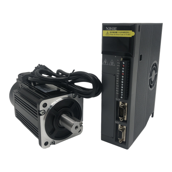
Xinje DS2 series User Manual (98 pages)
Brand:
Xinje
| Category:
Servo Drives
| Size: 3.81 MB
Table of Contents
Table of Contents
5
Preface
10
1 Checking Product and Part Names
11
Checking Products on Delivery
11
Servomotors
11
Servo Drivers
12
Adaptation Table of Servo Drive and Motor
13
Product Part Names
13
Servomotors
13
Servo Drivers
14
Servomotor
16
Storage Temperature
16
Installation Site
16
Concentricity
16
Orientation
17
Handling Oil and Water
17
Cable Stress
17
Servo Drivers
17
Storage Conditions
17
Installation Site
17
Orientation
18
Installation
18
3 Wiring
20
Main Circuit Wiring
20
Names and Descriptions of Main Circuit Terminal
20
Typical Wiring Example
21
Winding Terminals on Servo Motor
22
I/O Signals
22
Layout of CN0/CN1 Terminals
22
CN0 and CN1
22
I/O Signal Names and Functions
24
Interface Circuits
24
Wiring Encoders
26
Encoder Connections
26
CN2 Encoder Connector Terminal Layout
27
Standard Connection Examples
27
Position Control Mode
28
Communication Port
30
Serial Port 1(COM1)
30
Serial Port 2(COM2)
31
Regenerative Resistor
31
4 Use the Operate Panel
33
Basic Operation
33
Functions of Operate Panel
33
Basic Mode Switching
33
Running Status Mode
34
Monitoring Mode
35
Auxiliary Function
37
Check System Infomation
38
Auxiliary Run Mode
38
Change the Motor Type
39
Check Alarm Information
40
Reset Parameters to Default
40
External Monitoring
40
Parameter Setting
40
Alarm
41
5 Run the Servo System
42
Control Mode Selection
42
Basic Function Setting
42
Servo on Setting
43
Switch the Motor Rotate Direction
43
Overtravel Limit (P-OT & N-OT)
43
Motor Stop Mode When Servo off
45
Power-Off Brake (BK)
45
Position Mode (External Pulse Command)
47
Control Mode Selection
48
Pulse Command
48
Pulse Mode Selection
48
Explanation of Command Pulse
48
Signal Connection
49
Electronic Gear Ratio
49
Parameter
49
Set the Electronic Gear
49
Example of Setting the Electronic Gear
50
Position Command Filter
50
Pulse Error Clear (/CLR)
51
Positioning Complete (/COIN)
51
Positioning Near (/NEAR)
52
Command Pulse Prohibition (/INHIBIT)
52
Position Mode (Internal Position Mode)
53
Control Mode Selection
53
Internal Position Given Mode
53
Position Parameters from Segment 1 to 16
56
Change Step (/CHGSTP)
56
Pause Current Signal (/INHIBIT)
56
Skip Current Signal (/ZCLAMP)
57
Reference Origin
57
Speed Control (Analog Voltage Command)
59
Control Mode Selection
59
Analog Value of Rated Speed
59
Speed Command Offset Auto-Adjustment (F1-03)
60
Proportion Action Command (/P-CON)
60
Zero Clamp (/ZCLAMP)
60
Speed Coincidence Checking (/V-CMP)
61
Torque Limit
61
Internal Torque Limit (Output Torque Max Value Limit)
61
External Torque Limit (Via Input Signal)
61
External Torque Limit (Via Analog Voltage Command)
62
External Torque Limit (Via External Input + Analog Voltage)
62
Output Torque up to Limit Value Signal
63
Soft Start
63
Filter
63
Speed Command Input Dead Voltage
64
Speed Control (Internal Speed)
64
Control Mode Selection
65
Internal Speed Setting
65
Input Signal Setting
65
Speed Control (Pulse Frequency Command)
66
Control Mode Selection
67
Pulse Frequency Command
67
Command Pulse Frequency at Rated Speed
67
Speed Command Pulse Filter Time
67
Torque Control (Analog Voltage Command)
67
Control Mode Selection
68
The Analog Value of Rated Torque
68
Torque Command Offset Autoadjustment (F1-04)
68
Torque Command Filter Time
68
Torque Limit
69
Internal Speed Limit
69
External Speed Limit
69
Speed up to Limit Value Output
69
Torque Command Input Dead Area Voltage
69
Torque Control (Internal Setting)
70
Control Mode Selection
70
Internal Torque Command
70
Switch the Control Mode
70
Other Output Signals
71
ALM and /ALM-RST
71
Warn
71
Rotation Checking (/TGON)
71
Servo Ready (/S-RDY)
71
Encoder Z Phase Output (/Z)
72
AB Phase Feedback Signal of Encoder
72
I/O Signal Distribution
72
Input Signal Distribution
72
Default Setting of Input Terminal
73
Output Terminal Distribution
74
Default Setting of Output Terminal
74
6 Servo Gain Adjustment
75
Servo Gain Setting
75
Gain Setting of Speed Loop
75
Gain Setting of Position Loop
75
Position Loop Proportion Gain
75
Position Loop Feedforward Gain
76
The Experience of Parameter Adjustment
76
Proportion Action Command (P-CON)
76
Gain Switch (G-SEL)
77
7 Specification and Dimension
78
Servo Motor
78
Servo Motor Specification
78
Torque-Speed Feature
80
Servo Motor Dimensions
81
Servo Drivers
84
General Specification
84
Performance Specification
85
Servo Driver Dimensions
86
8 Alarm Information
88
Appendix 1 Parameter List
90
Appendix 2 Application
96
Advertisement
Xinje DS2 series User Manual (99 pages)
DS2 Series
Brand:
Xinje
| Category:
Servo Drives
| Size: 2.8 MB
Table of Contents
Table of Contents
5
Preface
9
1 Checking Product and Part Names
10
Checking Products on Delivery
10
Product Appearance and Name Rule
10
Adaptation Table of Servo Drive and Motor
13
2 Installations
14
Servomotor
14
Storage Temperature
14
Installation Site
14
Concentricity
14
Orientation
15
Handling Oil and Water
15
Cable Stress
15
Servo Drive
15
Storage Conditions
15
Installation Site
15
Orientation
16
Installation
16
3 Wiring
18
Main Circuit Wiring
18
The Terminal Arrangement
18
Main Circuit Terminals
19
Winding Terminals on Servo Motor
21
CN0, CN1, CN2 Terminals
21
Communication Port
23
Signal Terminals
24
Pulse Signal
24
SI Input Signal
25
Analog Input Circuit
26
Output Signal
26
Encoder Feedback Signal
27
Standard Wiring Example
27
Position Control Mode
27
Regenerative Resistor
31
4 Use the Operate Panel
32
Basic Operation
32
Functions of Operate Panel
32
Basic Mode Switching
32
Running Status Mode
33
Monitoring Mode
34
Auxiliary Function
36
F0-XX
36
F1-XX
36
Change the Motor Type (F2-00)
37
Check Alarm Information (F3-XX)
38
Reset Parameters to Default (F4-XX)
38
External Monitoring (F5-XX)
38
Alarm (E-XX)
38
Example
38
5 Run the Servo System
40
Control Mode Selection
40
Basic Function Setting
40
Servo on Setting
41
Switch the Motor Rotate Direction
41
Motor Stop Mode When Use Overtravel Signal
41
Overtravel Limit (P-OT & N-OT)
42
Power-Off Brake (BK)
43
Alarm Output
44
Running Time
45
Torque Over-Limit
45
Position Mode (External Pulse Command)
45
Control Mode Selection
46
Pulse Command
46
Electronic Gear Ratio
47
Position Command Filter
48
Pulse Error Clear (/CLR)
49
Positioning Complete (/COIN)
49
Positioning Near (/NEAR)
50
Command Pulse Prohibition (/INHIBIT)
50
Position Mode (Internal Position Mode)
51
Control Mode Selection
51
Internal Position Mode
51
Position Parameters from Segment 1 to 16
54
Change Step (/CHGSTP)
54
Pause Current Signal (/INHIBIT)
54
Skip Current Signal (/ZCLAMP)
55
Reference Origin
55
Set Segment through Communication
57
Speed Control (Analog Voltage Command)
57
Control Mode Selection
57
Analog Value of Rated Speed
58
Speed Command Offset Auto-Adjustment (F1-03)
58
Proportion Action Command (/P-CON)
58
Zero Clamp (/ZCLAMP)
58
Speed Coincidence Checking (/V-CMP)
59
Torque Limit
59
Internal Torque Limit (Output Torque Max Value Limit)
59
External Torque Limit (Via Input Signal)
59
External Torque Limit (Via Analog Voltage Command)
60
External Torque Limit (Via External Input + Analog Voltage)
60
Output Torque up to Limit Value Signal
61
Soft Start
61
Filter
62
Speed Command Input Dead Voltage
62
Speed Control (Internal Speed)
62
Control Mode Selection
63
Internal Speed Setting
63
Input Signal Setting
64
Speed Control (Pulse Frequency Command)
65
Control Mode Selection
65
Pulse Frequency Command
65
Command Pulse Frequency at Rated Speed
65
Speed Command Pulse Filter Time
66
Torque Control (Analog Voltage Command)
66
Control Mode Selection
66
The Analog Value of Rated Torque
66
Torque Command Offset Autoadjustment (F1-04)
67
Torque Command Filter Time
67
Torque Limit
67
Internal Speed Limit
67
External Speed Limit
67
Speed up to Limit Value Output
68
Torque Command Input Dead Area Voltage
68
Torque Control (Internal Setting)
68
Control Mode Selection
68
Internal Torque Command
68
Switch the Control Mode
69
Other Output Signals
69
ALM and /ALM-RST
69
Warn
69
Rotation Checking (/TGON)
69
Servo Ready (/S-RDY)
70
Encoder Z Phase Output (/Z)
70
AB Phase Feedback Signal of Encoder
70
I/O Signal Distribution
71
Input Signal Distribution
71
Default Setting of Input Terminal
72
Output Terminal Distribution
72
Default Setting of Output Terminal
72
6 Servo Gain Adjustment
73
Gain Setting of Speed Loop
73
Gain Setting of Position Loop
73
The Experience of Parameter Adjustment
74
Proportion Action Command (P-CON)
74
Gain Switch (G-SEL)
75
7 Specification and Dimension
76
Servo Motor
76
Servo Motor Specification
76
Torque-Speed Feature
79
Servo Motor Dimensions
80
Servo Drives
84
General Specification
84
Performance Specification
84
Servo Drive Dimensions
85
8 Alarm Information
88
Appendix 1 Parameter List
90
Xinje DS2 series Manual (71 pages)
Brand:
Xinje
| Category:
Servo Drives
| Size: 1.88 MB
Table of Contents
Safety Notes
3
Confirmation after Getting the Products
3
Type
3
Servo Motor
4
Specification
5
Servo Drive
10
Parts Introduction
11
Installation
13
Storage Temperature
13
Installation Location
14
Concentricity
14
Installation Direction
14
Avoid Oil and Water
15
Cable Stress
15
Servo Drive Direction
17
Cooling
17
Side-By-Side Installation
17
Temperature in the Control Panel
17
Dimensions
18
60 Series Motor Installation Dimensions
18
80 Series Motor Installation Dimensions
19
90 Series Motor Installation Dimensions
20
110 Series Motor Installation Dimensions
21
130 Series Motor Installation Dimensions
22
180 Series Motor Installation Dimensions
23
Wiring
26
Main Circuit
26
The Terminal Function of Main Circuit
26
Winding Connector of Servo Motor
28
Ds2-20P7-Bsw/Bsw6
28
I/O Terminal (CN0, CN1)
29
CN0, CN1 Terminal
29
Cn1(Db15)Terminals
30
I/O Signals
31
Input Signal
31
Output Signal
31
CN2 Terminals
32
Communication Port
32
Com1
32
All Types
33
Com2
33
Regeneration Resistor
34
Typical Wiring
36
Use the Control Panel
39
Basic Operation
39
Key Operation
39
Display Mode
40
Running Status
41
Speed, Torque Control Mode
41
Bit Display
41
Code Contents
42
Position Control
42
Code Display
43
U-XX Monitor Status
44
U-21 I/O Signal Status
45
Input Signal Distribution
45
Output Signal Distribution
45
U-22 I/O Terminal Status
46
Auxiliary Function
47
Current Offset Auto-Tune
48
Speed Analog Value Auto-Tune
48
Test Run
48
Change the Motor Code (Parameter F2-00)
49
Check the Alarm Information(Parameter F3-XX)
49
Set to Default Value (Parameter F4-XX)
50
External Monitor (Parameter F5-XX)
50
Error Alarm Operation
50
Parameter Setting
51
Parameter List
52
Function Selection P0
52
Control Parameter P1
54
Position Control Parameter P2
55
Speed Control P3
57
Torque Control P4
58
Signal Parameter P5
59
Input Signal Distributions
64
Default Settings of Input Terminals
64
Alarm Information
65
Output Signal Distributions
65
The Default Settings of Output Terminals
65
General Debug Steps
67
Motor Code
68
Drive Type and Suitable Motor Code
69
Advertisement
Xinje DS2 series Manual (59 pages)
380V servo drive
Brand:
Xinje
| Category:
Servo Drives
| Size: 0.9 MB
Table of Contents
Safety Caution
3
Installation
3
Operation
3
Model Description
4
Installations
8
Servo Drive
10
Performance Specification
16
I/O Signal Names and Functions
21
Communication Port
22
Regenerative Resistor
24
Using the Operation Panel
26
Basic Operation
26
Running Status
28
I/O Signal Status
31
Auxiliary Function
33
Parameter List
38
Modbus Address
47
Alarm Information
54
Motor Code
57
Advertisement
Related Products
Xinje DS2-20P7-AS
Xinje DS2-20P4-AS
Xinje DS2-20P2-AS
Xinje DS2-45P5-A
Xinje DS2-47P5-A
Xinje DS2-20P2-AS6
Xinje DS2-20P4-BS6
Xinje DS2-20P7-AS6
Xinje DS2-20P7-BSW
Xinje DS2-20P7-BSW6
Xinje Categories
Servo Drives
Control Unit
Controller
Touch Panel
Computer Hardware
More Xinje Manuals
Login
Sign In
OR
Sign in with Facebook
Sign in with Google
Upload manual
Upload from disk
Upload from URL