Advantech PCA-6751 Series User Manual
Half-size all-in-one pentium cpu card with mmx cpu, vga/lcd and fast ethernet interface
Hide thumbs
Also See for PCA-6751 Series:
- Startup manual (4 pages) ,
- Manual (102 pages) ,
- User manual (113 pages)
Table of Contents
Advertisement
Quick Links
Download this manual
See also:
Manual
Advertisement
Table of Contents

Related Manuals for Advantech PCA-6751 Series


Summary of Contents for Advantech PCA-6751 Series
- Page 1 PCA-6751 Series ® Half-size all-in-one Pentium card with MMX CPU, VGA/LCD and Fast Ethernet interface User’s Manual...
-
Page 2: Copyright Notice
Copyright notice This document is copyrighted, 2000, by Advantech Co., Ltd. All rights are reserved. The original manufacturer reserves the right to make improvements to the products described in this manual at any time without notice. No part of this manual may be reproduced, copied, translated or transmitted in any form or by any means without the prior written permission of the original manufacturer. -
Page 3: Packing List
Packing list Before installing your board, ensure that the following materials have been received: • 1 PCA-6751 Series all-in-one single board computer • 2 utility disk with Ethernet utility programs • 430 TX chipset driver for Windows 95 • 3 utility disks with SVGA utility programs and drivers for Windows 3.1/95/98/NT... -
Page 4: Table Of Contents
VGA function ................3 Ethernet controller functions (PCA-6751 only) ......4 Solid state disk ................4 Mechanic and environmental specifications ........ 4 PCA-6751 Series' models comparison table ........ 4 Board layout: Dimensions ............5 Safety precautions ............... 6 Jumper settings................7 1.5.1 Introduction ................ - Page 5 2.11 External speaker connector (CN9) .......... 21 2.12 VGA display connector (CN11) ..........22 2.13 PC/104 connectors (CN12) ............22 2.14 Ethernet connector (CN13) (PCA-6751 only) ......22 2.14.1 RJ-45A connector (CN13) ..........22 2.14.2 Network boot ..............22 2.15 Serial ports (CN16: COM1; CN15: COM2/RS-232; CN14: COM2/RS-422/485) ............
- Page 6 Chapter 4 PCI SVGA Setup ..........41 Introduction ................42 4.1.1 Chipset ................42 4.1.2 Display memory ..............42 4.1.3 Display types ..............42 Installation of SVGA driver ............. 43 4.2.1 Installation for Windows 3.1 ..........44 4.2.2 Installation for Windows 95 ..........46 4.2.3 Installation for Windows NT ..........
- Page 7 Appendix A Programming the Watchdog Timer ....69 Programming the watchdog timer .......... 70 Appendix B Installing PC/104 Modules ......73 Installing PC/104 modules ............74 Appendix C Pin Assignments ..........77 Floppy drive connector (CN1) ..........78 Parallel port connector (CN2) ..........79 Keyboard lock, LED connector (CN3) ........
- Page 8 Table 2-2: Serial port connections (COM1, COM2) ........23 Table 2-3: Serial port default settings ............24 Table B-1: PCA-6751 Series PC/104 connectors (CN12) ....... 76 Table C-1: Floppy drive connector (CN1) ............78 Table C-2: Parallel port connector (CN2) ............79 Table C-3: Keyboard lock, LED connector (CN3) ...........
- Page 9 Figures Figure 1-1: PCA-6751 Series board layout: Dimensions ........5 Figure 3-1: Setup program initial screen ............30 Figure 3-2: CMOS setup screen ..............31 Figure 3-3: BIOS features setup screen ............32 Figure 3-4: Chipset features setup screen ............. 36 Figure 3-5: Power management setup screen ..........
-
Page 10: Chapter 1 Hardware Configuration
Hardware Configuration This chapter gives background informa- tion on the PCA-6751 Series. It then shows you how to configure the card to match your application and prepare it for installation into your PC. Sections include: • Card specifications • Board layout: Dimensions •... -
Page 11: Introduction
1.1 Introduction The PCA-6751 Series is a half-size ISA-bus CPU card designed with ® ® an onboard Intel Pentium MMX CPU. Featuring powerful onboard functions such as VGA, LCD, LAN and SSD, the versatile PCA-6751 Series can meet the needs of different applications. -
Page 12: Specifications
1.2 Specifications Standard SBC functions ® • CPU: Intel Pentium MMX CPU 166/266 MHz • BIOS: AWARD 2 Mbit Flash BIOS, supports Plug & Play, APM 1.2, Ethernet boot ROM, boot from CD-ROM, LS-120, and ZIP drive ® • Chipset: Intel 430 TX •... -
Page 13: Ethernet Controller Functions (Pca-6751 Only)
Mechanic and environmental specifications • Max. power requirement: 5 A @ +5 V • Operating temperature: 0 ~ 70° C (32 ~ 166° F) • Size: 185 mm x 122 mm PCA-6751 Series' models comparison table Model Name Brief description A1 version... -
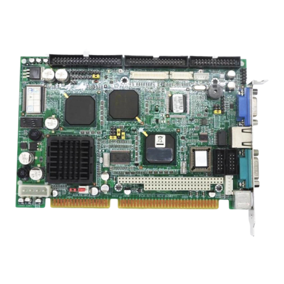
Page 14: Board Layout: Dimensions
157.44 155.13 111.95 109.84 108.53 106.47 104.04 103.45 101.84 102.18 99.64 81.86 54.17 25.64 25.98 23.44 23.44 18.36 15.44 13.82 12.03 7.23 7.62 8.48 5.00 4.00 0.00 Unit: mm Figure 1-1: PCA-6751 Series board layout: Dimensions Chapter 1 Hardware Configuration... -
Page 15: Safety Precautions
Keep the card in its antistatic packaging when it is not installed in the PC, and place it on a static dissipa- tive mat when you are working with it. Wear a grounding wrist strap for continuous protection. PCA-6751 Series User's Manual... -
Page 16: Jumper Settings
1.5 Jumper settings 1.5.1 Introduction This section tells how to set the jumpers to configure your card. It gives the card default configuration and your options for each jumper. After you set the jumpers and install the card, you will also need to run the BIOS Setup program (discussed in Chapter 3) to configure the serial port addresses, floppy/hard disk drive types and system operat- ing parameters. -
Page 17: Locating Jumpers
Table 1-1: Jumpers Label Function COM2 setting for RS-232/422/485 LCD panel select CMOS backup select Watchdog timer configuration 1.5.2 Locating jumpers PCA-6751 Series User's Manual... -
Page 18: Com2 Settings For Rs-232/422/485 (Jp1)
1.5.3 COM2 settings for RS-232/422/485 (JP1) Table 1-2: COM2 settings for RS-232/422/485 (JP1) *RS-232 RS-422 RS-485 * default setting 1.5.4 LCD panel select (JP2) Chapter 1 Hardware Configuration... -
Page 19: Table 1-3: Lcd Panel Select (Jp2)
1024 x 768 TFT 800 x 600 DSTN 640 x 480 DSTN 48 K 1024 x 768 DSTN 640 x 480 Sharp 48 K 800 x 600 TFT1 1024 x 768 DSTN 48 K * default setting PCA-6751 Series User's Manual... -
Page 20: Cmos Backup Select (Jp3)
1.5.5 CMOS backup select (JP3) Warning: To avoid damaging the computer, always turn off the power supply before setting "Clear CMOS". Set the jumper back to normal before turning on the power supply. Table 1-4: RTC power and CMOS clear (JP3) *Normal CMOS data clear * default setting... -
Page 21: Watchdog Timer Configuration (Jp4)
IRQ 11, depending on the setting of jumper JP4, as shown below: Table 1-5: Watchdog timer system reset select (JP4) *System reset IRQ11 interrupt * default setting PCA-6751 Series User's Manual... -
Page 22: Installing System Memory (Sodimms)
1.6 Installing system memory (SODIMMs) You can install anywhere from 8 to 256 MB of SDRAM into your PCA-6751 Series card. The card provides two 144-pin SODIMM sockets. Each socket accepts 8, 16, 32, 64 or 128 MB 3.3 V power level SODIMMs. - Page 23 Important: Only use standard form SODIMM memory modules (as shown in the diagram below). Standardized dimensions ensure a proper fit. Check with your memory supplier about the SODIMM modules you will use. PCA-6751 Series User's Manual...
-
Page 24: Chapter 2 Connecting Peripherals
Peripherals This chapter tells how to connect peripherals, switches and indicators to the PCA-6751 Series board. You can access most of the connectors from the top of the board while it is installed in the chassis. If you have a number of cards installed, or... -
Page 25: Board Layout: Connector Locations (Component Side)
Board layout: Connector locations (component side) CN20 CN28 CN18 CN25 CN26 CN22 CN23 CN12 PCA-6751 Series User's Manual... -
Page 26: Board Layout: Connector Locations (Solder Side)
Board layout: Connector locations (solder side) CN24 Chapter 2 Connecting Peripherals... -
Page 27: Table 2-1: Connectors
The following table lists the connectors on the PCA-6751 Series. Table 2-1: Connectors Number Function FDD connector Parallel port connector Keyboard lock, LED connector USB connector 24-bit LCD display connector 36-bit LCD display connector LCD inverter connector IR connector External speaker connector... -
Page 28: Fdd Connector (Cn1)
FDD connector (CN1) You can attach up to two floppy disk drives to the PCA-6751 Series’ onboard controller. You can use any combination of 5.25" (360 KB/ 1.2 MB) and/or 3.5" (720 KB/1.44/2.88 MB) drives. -
Page 29: Parallel Port Connector (Cn2)
Connecting CN3 enables the keyboard locking function from the front panel of your chassis. USB connector (CN4) The PCA-6751 Series board provides two USB (Universal Serial Bus) interfaces, which give complete plug and play and also hot attach/detach for up to 127 external devices. The USB interfaces comply with USB specification rev. -
Page 30: 24-Bit Lcd Display Connector (Cn5)
Refer to Chapter 4 for details. 36-bit LCD display connector (CN6) The PCA-6751 Series supports 36-bit LCD that must be connected to both CN5 (40-pin) and CN6 (20-pin). The pin assignments for both CN5 and CN6 can be found in Appendix C. -
Page 31: Vga Display Connector (Cn11)
2.12 VGA display connector (CN11) The PCA-6751 Series provides a VGA controller for a high resolution VGA interface. The PCA-6751Series' CN7 is a DB-15 connector for VGA monitor input. Pin assignments for the CRT display are detailed in Appendix C. -
Page 32: Serial Ports (Cn16: Com1; Cn15: Com2/Rs-232; Cn14: Com2/Rs-422/485)
2.15 Serial ports (CN16: COM1; CN15: COM2/RS-232; CN14: COM2/RS-422/485) The PCA-6751 Series offers two serial ports: COM1 in RS-232 and COM2 (CN15: RS-232, CN14:RS-422/485). These ports let you connect to serial devices (a mouse, printers, etc.) or a communication network. -
Page 33: Rs-232/422/485 Connection (Com2: Cn15: Rs-232; Cn14: Rs-422/485)
For external keyboard pin assignments, see Appendix D. 2.17 ATX power connector (CN18) If the PCA-6751 Series is used as a standalone card, both the 4-pin main power connector (CN20) and the ATX power connector (CN18) must be connected to the power supply. If the PCA-6751 Series is... -
Page 34: At Power Connector (Cn20)
2.18 AT power connector (CN20) If you prefer not to acquire power through PCA-6751 Series' back- plane via the gold H-connectors, CN20 also provides power input connectors for +5 V, -12 V and +12 V. Pin 8 of the PS/2 power supply can be used, too. -
Page 35: Front Panel Connector (Cn25, Cn26, Cn27)
(CN25, CN26, CN27) Next, you may want to install external switches to monitor and control the PCA-6751 Series. These features are optional - install them only if you need them. The front panel connector provides connections for both a speaker and a hard disk access indicator, and it also provides an input switch for resetting the card and the ATX system power switch. -
Page 36: Enhanced Ide Connector (Cn28)
2.23 Enhanced IDE connector (CN28) You can attach two IDE (Integrated Device Electronics) drives to the PCA-6751 Series' internal controller. The PCA-6751 Series CPU card has an EIDE connector, CN28. Wire number 1 on the cable is red or blue, and the other wires are gray. -
Page 37: Atx Feature Connector (Cn27)
3-pin connector (female type) which connects to the ATX feature connector (CN27) on the board itself. This end also has the 6-pin main power connector (P8) and a 6-pin connector (P9) which is used when the board is mounted on a passive backplane. PCA-6751 Series User's Manual... -
Page 38: Chapter 3 Award Bios Setup
Award BIOS Setup This chapter describes how to set the card’s BIOS configuration data. -
Page 39: Introduction
This type of information is stored in battery-backed RAM so that it retains the Setup information when the power is turned off. 3.2 Entering setup Turning on the computer and pressing <DEL> immediately will allow you to enter Setup. PCA-6751 Series User's Manual... -
Page 40: Standard Cmos Setup
3.3 Standard CMOS setup Choose the “STANDARD CMOS SETUP” option from the INITIAL SETUP SCREEN Menu, and the screen below is displayed. This standard Setup Menu allows users to configure system components such as date, time, hard disk drive, floppy drive, display, and memory. Figure 3-2: CMOS setup screen Chapter 3 Award BIOS Setup... -
Page 41: Bios Features Setup
The “BIOS FEATURES SETUP” screen appears when choosing the BIOS FEATURES SETUP item from the CMOS SETUP UTILITY Menu. It allows the user to configure the PCA-6751 Series according to his particular requirements. Below are some major items that are provided in the BIOS FEA-... - Page 42 Quick Power On Self Test This option speeds up the Power-On Self Test (POST) conducted as soon as the computer is turned on. When enabled, BIOS shortens or skips some of the items during the test. When disabled, normal POST procedures assumes.
- Page 43 Typematic Delay (msec) When holding down a key, the Typematic Delay is the time interval between the appearance of the first and second characters. The input values (msec) for this category are: 250, 500, 750, 1000. PCA-6751 Series User's Manual...
- Page 44 Security Option This setting determines whether the system will boot if the password is denied, while limiting access to Setup. System The system will not boot, and access to Setup will be denied if the correct password is not entered at the prompt. Setup The system will boot, but access to Setup will be denied if the correct password is not entered at the prompt.
-
Page 45: Chipset Features Setup
By choosing the “CHIPSET FEATURES SETUP” option from the INITIAL SETUP SCREEN Menu, the screen below is displayed. This sample screen contains the manufacturer’s default values for the PCA-6751 Series. Figure 3-4: Chipset features setup screen PCA-6751 Series User's Manual... -
Page 46: Power Management Setup
3.6 Power management setup The power management setup controls the CPU cards’ “green” features. The following screen shows the manufacturer’s default. Figure 3-5: Power management setup screen Power Management This option allows you to determine if the values in power manage- ment are disabled, user-defined, or predefined. -
Page 47: Pnp Pci Configuration Setup
These default values are loaded automatically if the stored record created by the Setup program becomes corrupted (and therefore unusable). 3.9 Load setup defaults “LOAD SETUP DEFAULTS” loads the values required by the system for maximum performance. PCA-6751 Series User's Manual... -
Page 48: Integrated Peripherals
3.10 Integrated peripherals Figure 3-7: Integrated peripherals Note: If you enable the IDE HDD block mode, the en- hanced IDE driver will be enabled. 3.11 Password setting To change, confirm, or disable the password, choose the “PASS- WORD SETTING” option form the Setup main menu and press [Enter]. -
Page 49: Ide Hdd Auto Detection
This record is required for the system to operate. 3.14 Exit without saving Selecting this option and pressing the [Enter] key lets you exit the Setup program without recording any new values or changing old ones. PCA-6751 Series User's Manual... -
Page 50: Chapter 4 Pci Svga Setup
PCI SVGA Setup • Introduction • Installation of SVGA driver - for Windows 3.1 - for Windows 95 - for Windows NT • Further information... -
Page 51: Introduction
4.1 Introduction The PCA-6751 Series has an onboard PCI flat panel/VGA interface. The specifications and features are described as follows: 4.1.1 Chipset The PCA-6751 Series uses a C&T 69000/69030 chipset for its PCI/SVGA controller. It supports many popular LCD, EL, and gas plasma flat panel displays and conventional analog CRT monitors. -
Page 52: Installation Of Svga Driver
Complete the following steps to install the SVGA driver. Follow the procedures in the flow chart that apply to the operating system that you you are using within your PCA-6751 Series. Important: The following windows illustrations are examples only. You must follow the flow chart instructions and pay attention to the instructions which then appear on your screen. -
Page 53: Installation For Windows 3.1
D:\SlotPC\6751\VGA\69000\Win31 Program Manager. c. Click "Run" and type: D:\SlotPC\ 6751\VGA\69000\ Win31 a. Choose the language you want to use during installation. a. Select the highlighted item. b. Press "ENTER". a. Press "ENTER" to install all resolutions. PCA-6751 Series User's Manual... - Page 54 a. Type the path of the operating system. a. When installation is completed, reboot the system. b. You will see the "ChipsCPL" icon in the control panel. ChipsCPL a. Double click "ChipsCPL". b. Adjust screen size, color and refresh rate to your preferences.
-
Page 55: Installation For Windows 95
Press "Advanced Properties". a. Choose the "Adapter" label. b. Press the "Change..." button. a. Press the "Have Disk" button. a. Insert the utility disc into the CD-ROM drive. b. Type: D:\SlotPC\ 6751\VGA\69000\ Win95 D:\SlotPC\6751\VGA\69000\Win95 c. Press "OK". PCA-6751 Series User's Manual... - Page 56 a. Select the highlighted item. 69000 b. Click the "OK" button. 69000 a. C&T69000/69030 appears in the adapter label. b. Click the "Apply" button. a. Press "Yes" to reboot. a. Repeat Step 1 on the previous page of this manual. The "CHIPS"...
- Page 57 Press "OK" to exit. a. Press "Yes" to set the monitor type. a. Select "Standard", "Super VGA 800 x 600", or "XGA". b. Press the "OK" button. a. Choose "Restart" to reboot. E N D PCA-6751 Series User's Manual...
-
Page 58: Installation For Windows Nt
4.2.3 Installation for Windows NT a. Select "Start", "Settings", "Control Panel". b. Double click the "Display" icon. a. Choose the "Settings" label. b. Press the "Display Type" button. a. Press the "Change..." button. a. Click the "Have Disk..." button. Chapter 4 PCI SVGA Setup... - Page 59 Insert the utility disc into the CD-ROM drive. b. Type D:\SlotPC\6751\ VGA\NT40\ c. Press the "OK" button. D:\SlotPC\6751\VGA\NT40\ a. Select the highlighted item. b. Press the "OK" button. a. Press "Yes" to proceed. a. Press "OK" to reboot. PCA-6751 Series User's Manual...
- Page 60 a. Repeat Step 1 in this manual, to select the "Settings" label. b. Adjust resolution and color. c. Click "Test" to see the result. d. Click "OK" to save the setting. E N D Chapter 4 PCI SVGA Setup...
-
Page 61: Further Information
4.3 Further information For more information about the PCI/SVGA installation in your PCA-6751 Series, including driver updates, troubleshooting guides and FAQ lists, visit the following web resources: C&T website: www.chips.com Advantech websites: www.advantech.com www.advantech.com/support PCA-6751/6751V Series User's Manual... -
Page 62: Chapter 5 Pci Bus Ethernet Interface With Intel Sb82558/Sb82559 (Pca-6751 Only)
PCI Bus Ethernet ® Interface With Intel SB82558/SB82559 (PCA-6751 only) This chapter provides information on Ethernet configuration. • Introduction • Installation of Ethernet driver - Installation for MS-DOS and Windows 3.1 - Installation for Windows 95 - Installation for Windows NT •... -
Page 63: Introduction
Then choose the correct driver to install in your panel PC. The installation procedures for various servers can be found in the directory path "LAN/TXT/*" of the drivers and utilities disks, where * is your server model. PCA-6751 Series User's Manual... -
Page 64: Installation For Windows 95
5.2.2 Installation for Windows 95 a. Select "Start", "Settings", "Control Panel". b. Double click "Network". a. Click "Add" and prepare to install network functions. a. Select the "Adapter" item to add the Ethernet card. a. Click "Have Disk" to install the driver. Chapter 5 PCI Bus Ethernet Interface With Intel ®... - Page 65 Type: D:\SlotPC\ 6751\Ether.100\ 82558\Win95\ Setup.exe D:\SlotPC\6751\Ether.100\82558\Win95\Setup.exe c. Click "OK". a. Choose the "Intel" item. b. Click "OK". a. Make sure the configurations of the relevant items are set correctly. b. Click "OK" to reboot. E N D PCA-6751 Series User's Manual...
-
Page 66: Installation For Windows Nt
5.2.3 Installation for Windows NT a. Select "Start", "Settings", "Control Panel". b. Double click "Network". a. Choose the "Adapters" label. b. Click the "Add" button. a. Press "Have Disk". a. Type "D:". b. Press "OK". Chapter 5 PCI Bus Ethernet Interface With Intel ®... - Page 67 Type: D:\SlotPC\ 6751\Ether.100\ 82558\Winnt\ D:\SlotPC\6751\Ether.100\82558\Winnt\ c. Click "OK". a. Choose the "Realtek" item. b. Click "OK". a. Make sure the configurations of relevant items are set correctly. b. Click "OK" to reboot. E N D PCA-6751 Series User's Manual...
-
Page 68: Further Information
5.3 Further information ® Intel website: www.intel.com Advantech websites: www.advantech.com www.advantech.com/support Chapter 5 PCI Bus Ethernet Interface With Intel ® SB82558/SB82559 (PCA-6751 only) - Page 69 PCA-6751 Series User's Manual...
-
Page 70: Chapter 6 Pci Bus Ethernet Interface With Rtl-8139 (Pca-6751 Only)
PCI Bus Ethernet Interface With RTL-8139 (PCA-6751 only) This chapter provides information on Ethernet configuration. • Introduction • Installation of Ethernet driver - for Windows 95/98 - for Windows NT • Further information... -
Page 71: Introduction
For example, MS-NT, IBM-LAN server, and so on. Then choose the correct driver to install in your panel PC. The installation procedures for various servers can be found on CD-ROM. The file path is: D:\SlotPC\6751\Ethernet\8139\wfw311 PCA-6751 Series User's Manual... -
Page 72: Installation For Windows 95/98
6.2.2 Installation for Windows 95/98 a. Select "Start", "Settings", "Control Panel". b. Double click "Network". a. Click "Add" and prepare to install network functions. a. Select the "Adapter" item to add the Ethernet card. a. Click "Have Disk" to install the driver. Chapter 6 PCI Bus Ethernet Interface With RTL-8139 (PCA-6751 only) - Page 73 Choose the "Realtek" item. b. Click "OK". a. Make sure the configurations of relevant items are set correctly. b. Click "OK" to reboot. E N D Note: The correct path for Windows 98 is: D:\SlotPC\6751\Ethernet\8139\Win98\ PCA-6751 Series User's Manual...
-
Page 74: Installation For Windows Nt
6.2.3 Installation for Windows NT a. Select "Start", "Settings", "Control Panel". b. Double click "Network". a. Choose the "Adapters" label. b. Click the "Add" button. a. Press "Have Disk". a. Insert the utility disc into the CD-ROM drive. b. Type: D:\SlotPC\ 6751\Ethernet\8139\ Winnt\ D:\SlotPC\6751\Ethernet\8139Winnt\... - Page 75 Choose the "Realtek" item. b. Click "OK". a. Make sure the configurations of relevant items are set correctly. b. Click "OK" to reboot. E N D PCA-6751 Series User's Manual...
-
Page 76: Further Information
6.3 Further information Realtek website: www.realtek.com Advantech websites: www.advantech.com www.advantech.com/support Chapter 6 PCI Bus Ethernet Interface With RTL-8139 (PCA-6751 only) - Page 77 PCA-6751 Series User's Manual...
-
Page 78: Appendix A Programming The Watchdog Timer
Programming the Watchdog Timer The PCA-6751 Series is equipped with a watchdog timer that resets the CPU or generates an interrupt if processing comes to a standstill for any reason. This feature ensures system reliability in industrial standalone or unmanned environments. -
Page 79: Programming The Watchdog Timer
The value range is from 01 (hex) to 3E (hex), and the related time interval is 1 sec. to 62 sec. Data Time Interval 1 sec. 2 sec. 3 sec. 4 sec. • • • • • • 62 sec. PCA-6751 Series User's Manual... - Page 80 After data entry, your program must refresh the watchdog timer by rewriting the I/O port 443 (hex) while simultaneously setting it. When you want to disable the watchdog timer, your program should read I/O port 443 (hex). The following example shows how you might program the watchdog timer in BASIC: Watchdog timer example program OUT &H443, data REM...
- Page 81 PCA-6751 Series User's Manual...
-
Page 82: Appendix B Installing Pc/104 Modules
Installing PC/104 Modules This appendix gives instructions for installing PC/104 modules. -
Page 83: Installing Pc/104 Modules
The PCA-6751 Series' PC/104 connectors give you the flexibility to attach PC/104 modules. Installing these modules on the PCA-6751 Series is quick and simple. The following steps show how to mount the PC/104 modules: 1. Remove the PCA-675 Series from your system paying particular attention to the safety instructions already mentioned above. -
Page 84: Figure B-1: Pc/104 Module Mounting Diagram
P C /1 0 4 M o u n tin g S u p p o rt F e m a le M a le P C /1 0 4 m o d u le P C A -6 7 5 1 S e rie s Figure B-1: PC/104 module mounting diagram 82.5 95.9... -
Page 85: Table B-1: Pca-6751 Series Pc/104 Connectors (Cn12)
Table B-1: PCA-6751 Series PC/104 connectors (CN12) Signal (CN12) Number Row A Row B Row C Row D — — IOCHCHK* SBHE* MEMCS16* RESETDRV LA23 IOCS16* +5 V LA22 IRQ10 IRQ9 LA21 IRQ11 -5 V LA20 IRQ12 DRQ2 LA19 IRQ15... -
Page 86: Appendix C Pin Assignments
Pin Assignments This appendix contains information of a detailed or specialized nature. It includes: • FDD connector • Parallel port connector • Keyboard lock connector • USB connector • 24-bit LCD display connector • 36-bit LCD display connector • LCD inverter connector •... -
Page 87: Floppy Drive Connector (Cn1)
Table C-1: Floppy drive connector (CN1) Signal Signal DENSITY SELECT* INDEX* MOTOR 0* DRIVE SELECT 1* DRIVE SELECT 0* MOTOR 1* DIRECTION* STEP* WRITE DATA* WRITE GATE* TRACK 0* WRITE PROTECT* READ DATA* HEAD SELECT* DISK CHANGE* * low active PCA-6751 Series User's Manual... -
Page 88: Parallel Port Connector (Cn2)
C.2 Parallel port connector (CN2) Table C-2: Parallel port connector (CN2) Signal *STROBE *AUTOFD *INIT *SLCTINI *ACK BUSY SLCT * low active Appendix C Pin Assignments... -
Page 89: Keyboard Lock, Led Connector (Cn3)
C.3 Keyboard lock, LED connector (CN3) Table C-3: Keyboard lock, LED connector (CN3) Signal +5 V KBLOCK C.4 USB1/USB2 connector (CN4) Table C-4: USB1/USB2 connector (CN4) USB1 USB2 Signal Signal +5 V +5 V Chassis GND PCA-6751 Series User's Manual... -
Page 90: 24-Bit Lcd Display Connector (Cn5)
C.5 24-bit LCD display connector (CN5) Table C-5: 24-bit LCD display connector (CN5) Signal Signal VDDSAFE5 VDDSAFE5 VDDSAFE3 VDDSAFE3 Vcon SHIFT CLOCK FILM ENAVEE Note: The model number of the CN18 socket is DF13A-40DP-1.25V (Hirose Electric Co., Ltd.) Appendix C Pin Assignments... -
Page 91: 36-Bit Lcd Display Connector (Cn6)
C.6 36-bit LCD display connector (CN6) Table C-6: 36-bit LCD display connector (CN6) Signal Signal Note: The model number of the CN19 socket is DF13A-20DP-1.25V (Hirose Electric Co., Ltd.) PCA-6751 Series User's Manual... -
Page 92: Lcd Inverter Connector (Cn7)
C.7 LCD inverter connector (CN7) Table C-7: LCD inverter connector (CN7) Signal +12 V ENABKL + 5 V C.8 IR connector (CN8) Table C-8: IR connector (CN8) Signal +5 V IR_RX IR_TX Appendix C Pin Assignments... -
Page 93: External Speaker Connector (Cn9)
C.9 External speaker connector (CN9) Table C-9: External speaker connector (CN9) Signal + 5 V Internal speaker External speaker C.10 VGA connector (CN11) Table C-10: VGA connector (CN11) Signal Signal GREEN BLUE H-SYNC V-SYNC PCA-6751 Series User's Manual... -
Page 94: Pc/104 Connector (Cn12)
C.11 PC/104 connector (CN12) For details on PC/104 connectors, please refer to Appendix B. C.12 Ethernet connector (CN13) Table C-11: Ethernet connector (CN1) Signal Signal Vcc (+5 V) ACTLED- LILED- Appendix C Pin Assignments... -
Page 95: Com2 Rs-422/485 Connector (Cn14)
C.13 COM2 RS-422/485 connector (CN14) Table C-12: COM2 RS-232/422/485 connector (CN14) RS-232 port RS-422 port RS-485 port TXD- DATA- TXD+ DATA+ RXD+ RXD- PCA-6751 Series User's Manual... -
Page 96: Com2 Rs-232 Connector (Cn15)
C.14 COM2 RS-232 connector (CN15) Table C-13: COM2 RS-232 connector (CN15) RS-232 port RS-232 port Appendix C Pin Assignments... -
Page 97: Com1 Rs-232 Connector (Cn16)
C.15 COM1 RS-232 connector (CN16) Table C-14: COM1 RS-232 connector (CN16) Signal C.16 External keyboard connector (CN17) Table C-15: External keyboard connector (CN17) Signal DATA + 5 V PCA-6751 Series User's Manual... -
Page 98: Atx Power Connector (Cn18)
C.17 ATX power connector (CN18) Table C-16: ATX power connector (CN18) Signal 5 V SB PS_ON C.18 AT power connector (CN20) Table C-17: AT power connector (CN20) Signal +12 V +5 V Appendix C Pin Assignments... -
Page 99: Keyboard And Ps/2 Mouse Connector (Cn21)
C.19 Keyboard and PS/2 mouse connector (CN21) Table C-18: Keyboard and PS/2 mouse connector (CN21) Signal KB DATA MS DATA +5 V PCA-6751 Series User's Manual... -
Page 100: Compactflash™ Card Connector (Cn24)
C.20 CompactFlash™ card connector (CN24) Table C-19: CompactFlash™ card connector (CN24) Signal Signal *CS0 *ATA SEL +5 V -IOCS16 *CD2 -CD1 -CS1 *VS1 -IORD *IOWR INTRQ +5 V *CSEL -VS2 *RESER IORDY *INPACK -REG *DASP -PDIAG * low active Appendix C Pin Assignments... -
Page 101: Hdd Led Connector (Cn25)
IDE LED + IDE LED - C.22 System reset switch connector (CN26) Table C-21: System reset switch connector (CN26) Signal MR_RESET C.23 ATX power button (CN27) Table C-22: ATX power button (CN27) Signal Standby 5 V Power ON PCA-6751 Series User's Manual... -
Page 102: Enhanced Ide Connector (Cn28)
C.24 Enhanced IDE connector (CN28) Table C-23: Enhanced IDE connector (CN28) Signal Signal IDE RESET* DATA 7 DATA 8 DATA 6 DATA 9 DATA 5 DATA 10 DATA 4 DATA 11 DATA 3 DATA 12 DATA 2 DATA 13 DATA 1 DATA 14 DATA 0 DATA 15... - Page 103 PCA-6751 Series User's Manual...
-
Page 104: Appendix D System Assignments
System Assignments This appendix contains information of a detailed or specialized nature. It includes: • System I/O ports • DMA channel assignments • Interrupt assignments • 1st MB memory map... -
Page 105: System I/O Ports
Monochrome display and printer adapter (LPT1) 3C0-3CF Reserved 3D0-3DF Color/graphics monitor adapter 3F0-3F7 Diskette controller 3F8-3FF Serial port 1 * PNP audio I/O map range from 220 ~ 250H (16 bytes) MPU-401 select from 300 ~ 330H (2 bytes) PCA-6751 Series User's Manual... -
Page 106: Dma Channel Assignments
D.2 DMA channel assignments Table D-2: DMA channel assignments Channel Function Available Available Floppy disk (8-bit transfer) Available Cascade for DMA controller 1 Available Available Available * Audio DMA select 0, 1 or 3 Appendix D System Assignments... -
Page 107: Interrupt Assignments
Serial communication port 1 IRQ 5 Parallel port 2 IRQ 6 Diskette controller (FDC) IRQ 7 Parallel port 1 (print port) * PNP audio IRQ select: 5, 7, 9 or 10 * Ethernet function is auto-sensing PCA-6751 Series User's Manual... -
Page 108: 1St Mb Memory Map
D.4 1st MB memory map Table D-4: 1st MB memory map Addr. range (Hex) Device F000h - FFFFh System ROM CB00h - EFFFh Unused C000h - CAFFh Expansion ROM B800h - BFFFh CGA/EGA/VGA text B000h - B7FFh Unused A000h - AFFFh EGA/VGA graphics 0000h - 9FFFh Base memory... - Page 109 PCA-6751 Series User's Manual...
-
Page 110: Appendix E Lcd Services
LCD Services This appendix contains information on Advantech's LCD lighting services. -
Page 111: Lcd Services
LCD inverter and all other factors that affect the successful installation of LCD panels. The following information details our LCD lighting services: a) This policy is only valid for Advantech products that include LCD support b) The customer should send the following LCD components for service: •...
Need help?
Do you have a question about the PCA-6751 Series and is the answer not in the manual?
Questions and answers