
Related Manuals for Advantech PCA-6028


Summary of Contents for Advantech PCA-6028
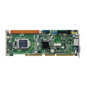
- Page 1 User Manual PCA-6028 Intel® Core™i7/i5/i3/Pentium® PICMG 1.0 Single Host Board with VGA/ DVI-D/ DDR3 /SATA3.0 / USB3.0 / Dual GbE...
- Page 2 No part of this manual may be reproduced, copied, translated or transmitted in any form or by any means without the prior written permission of Advantech Co., Ltd. Information provided in this manual is intended to be accurate and reliable. How- ever, Advantech Co., Ltd.
-
Page 3: Declaration Of Conformity
Whether your new Advantech equipment is destined for the labo- ratory or the factory floor, you can be assured that your product will provide the reliability and ease of operation for which the name Advantech has come to be known. - Page 4 Memory Compatibility PCA-6028 Compatible Memory Brand Size Speed Type ECC Vendor PN Memory Advantech PN DDR3 ELPIDA J1108BDBG-DJ-F DDR3 78.01GC3.420 96D3-1G1066NN-AP 1066 (128x8) DDR3 ELPIDA J1108BDBG-DJ-F DDR3 78.A1GC3.421 96D3-2G1066NN-AP 1066 (128x8) DDR3 HYNIX H5TQ2G83BFR- DDR3 78.B1GDJ.AF1 1066 DDR3 H5TQ1G83DFR-H9C DDR3 78.01GC6.AF0...
-
Page 5: Processor Support
Core I7-4770S 3.1GHz 8M10T 96MPI7- 2.3- Core I7-4770TE 2.3GHz 8M10T 96MPI5- 2.9- Core i5-4570S 2.9GHz 6M10T 96MPI5- 2.7- Core i5-4570TE 2.7GHz 4M10T PCA-6028 Haswell 22nm 1600 Core i3-4330 3.5GHz Core i3-4330TE 2.4GHz Pentium G3420 3.2GHz Pentium G3320TE 2.3GHz PCA-6028 User Manual... - Page 6 It should be free of marks and scratches and in perfect working order upon receipt. As you unpack the PCA-6028, check it for signs of ship- ping damage. (For example, damaged box, scratches, dents, etc.) If it is damaged or it fails to meet the specifications, notify our service department or your local sales representative immediately.
-
Page 7: Table Of Contents
Table 1.2: Connectors ..............5 Board Layout: Jumper and Connector Locations........6 Figure 1.1 Jumper and connector locations......... 6 Block Diagram................... 7 Figure 1.2 PCA-6028 Block Diagram........... 7 Safety Precautions ..................8 Jumper Settings ..................8 1.8.1 How to set jumpers ............... 8 1.8.2... - Page 8 Security..................56 Figure 3.30Security ..............56 3.2.6 Save & Exit ................. 57 Figure 3.31Save & Exit............... 57 Chapter Value-Added Software Services ..59 Value-Added Software Services ............. 60 4.1.1 Software API................60 4.1.2 Software Utility................61 PCA-6028 User Manual viii...
- Page 9 USB 2.0 Header (USB56 & 910)............. 87 Table B.4: USB Header (USB56 & 910) ........87 USB3.0 Header (USB12) ................ 88 Table B.5: USB 3.0 Header (USB12)......... 88 PS/2 Keyboard/Mouse Connector (KBMS1) ........... 88 Table B.6: PS/2 keyboard/mouse connector (KBMS1)....88 PCA-6028 User Manual...
- Page 10 Table B.21:1 MB memory map ........... 95 B.22 PCI Bus Map................... 95 Table B.22:PCI Bus Map ............95 Appendix C Programming the GPIO ....97 Supported GPIO Register ............... 98 GPIO Registers..................98 GPIO Example Program-1 ..............98 PCA-6028 User Manual...
-
Page 11: Chapter 1 Hardware Configuration
Chapter Hardware Configuration... -
Page 12: Introduction
Introduction PCA-6028 is a PICMG 1.0 form-factor single host board which is designed with Intel® H81 PCH for industrial applications that need high computing power and strong I/O capability.PCA-6028 supports 22nm manufacturing technology, LGA1150 socket Intel® Core™ i7/i5/i3 and Pentium® processors that integrate memory and graphic controllers and support DDR3 1333/1600 MHz SDRAM up to 16 GB. -
Page 13: Specifications
Memory RAM: – PCA-6028: Up to 16 GB in two 240-pin DIMM sockets. Supports dual-chan- nel DDR3 1333/1600 MHz SDRAM WITHOUT ECC function. Note! Due to the inherent limitations of PC architecture, the system may not fully detect 16 GB RAM when 16 GB RAM is installed. -
Page 14: Graphics
8GB x 2 Voltage +12 V +5 V +3.3 V +5 V Current 4.02 A 1.36 A 0.81 A 0.09 A Board size: 338.58 mm (L) x 126.39 mm (W) (13.3" x 4.98") Board weight: 0.5 kg PCA-6028 User Manual... -
Page 15: Jumpers And Connectors
Jumpers and Connectors Connectors on the PCA-6028 single host board link it to external devices such as hard disk drives and a keyboard. In addition, the board has a number of jumpers used to configure your system for your application. -
Page 16: Board Layout: Jumper And Connector Locations
DIMMA1 Memory connector channel A DIMMB1 Memory connector channel B GPIO1 GPIO pin header (SMD pitch-2.0 mm) LPC1 COM port module expansion pin-header Board Layout: Jumper and Connector Locations Figure 1.1 Jumper and connector locations PCA-6028 User Manual... -
Page 17: Block Diagram
Block Diagram Figure 1.2 PCA-6028 Block Diagram PCA-6028 User Manual... -
Page 18: Safety Precautions
1, 2 and 3. In this case you connect either pins 1 and 2, or 2 and 3. A pair of needle-nose pliers may be useful when set- ting jumpers. PCA-6028 User Manual... -
Page 19: Bios Cmos (Jcmos1)
1.8.3 Watchdog timer output (JWDT1) The PCA-6028 contains a watchdog timer that will reset the CPU in the event the CPU stops processing. This feature means the PCA-6028 will recover from a soft- ware failure or an EMI problem. The JWDT1 jumper settings control the outcome of what the computer will do in the event the watchdog timer is tripped. -
Page 20: System Memory
1.11 Cache Memory CPUs supported by PCA-6028 have 8 MB, 6 MB, 3 MB L3 cache memory sizes. Note! Please refer to Intel CPU data sheet for detail information. 1.12... - Page 21 Remove the socket protection cap. Align the cuts on the processor with the edges of the socket. Replace the socket cap; lower the retainer bar and clip it shut. PCA-6028 User Manual...
-
Page 22: Processor Cooler Installation
Advantech offers a specially designed CPU cooler for PCA-6028 for better heat dissi- pation efficiency and enhancing rigidity of CPU card, part number 1960047831N001. Buy it for PCA-6028 CPU card since it is NOT compatible with other brand CPU cool- ers (neither is it compatible with Intel boxed CPU cooler). -
Page 23: Chapter 2 Connecting Peripherals
Chapter Connecting Peripherals... -
Page 24: Introduction
USB Ports (USB01USB23,USB45,USB8,USB9,USB1011) The PCA-6028 provides up to 10 USB (Universal Serial Bus) on-board ports with complete Plug & Play and hot swap support for up to 127 external devices. These USB ports comply with USB Specification 2.0 and 3.0, support transfer rates up to 480 Mbps (USB2.0) and 5 Gbps (USB3.0). -
Page 25: Vga Connectors (Vga1)
15-pin D-SUB connector commonly used for VGA. Serial Ports (COM1 & COM2) The PCA-6028 offers two serial ports. These ports can connect to serial devices, such as a mouse or a printer, or to a communications network. The IRQ and address ranges for both ports are fixed. However, if you want to disable the port or change these parameters later, you can do this in the system BIOS setup. -
Page 26: Ps/2 Keyboard And Mouse Connector (Kbms1/Kbms2)
The on-board KBMS2 pin header provides connection to the front panel PS/2 key- board and mouse connector of the chassis. CPU Fan Connector (CPUFAN1) This fan connector support 3pin or 4pin fan cooler and smart fan function. note: Fan speed is controlled by voltage. PCA-6028 User Manual... -
Page 27: Front Panel Connectors (Jfp1, Jfp2 & Jfp3)
PWR_LED & Key Lock 2.8.2 External speaker (JFP2) JFP2 is a 4-pin connector for an external speaker. The PCA-6028 provides an onboard buzzer as an alternative to an external speaker. To enable the buzzer, set pins 3 and 4 as closed. -
Page 28: Reset Connector (Jfp1)
If your computer case is equipped with an ATX power supply, you should connect the power on/off button on your computer case to JFP1. This connection enables you to turn your computer on and off. JFP1 PWR_SW Reset HDD LED SNMP JFP2 Speaker JFP3 PWR_LED & Key Lock PCA-6028 User Manual... -
Page 29: H/W Monitor/Watchdog Timer/Infrared
Open: Disables OBS Alarm 2.9.2 Watchdog timer (JWDT1) This is for setting action trigger by watchdog timer. 1-2 Pin Close: No Action 2-3 Pin Close: System Reset 2.9.3 Infrared interface (JIR1) This is a 5-pin header for an infrared device. PCA-6028 User Manual... -
Page 30: Lan Ports (Lan1 & Lan2)
2.10 LAN Ports (LAN1 & LAN2) The PCA-6028 is equipped with one or two high-performance 1000 Mbps Ethernet LANs. They are supported by all major network operating systems. The RJ-45 jacks on the rear plate provide convenient connectivity. Table 2.2: LAN LED Indicators... -
Page 31: High Definition Audio Module Interface (Hdaud1)
2.11 High Definition Audio Module Interface (HDAUD1) This HDAUD1 pin header is the connection interface to Advantech's 7.1 channel high definition audio module. Note! Advantech 7.1 channel high definition audio module ordering informa- tion. P/N: PCA-AUDIO-HDA1E PCA-6028 User Manual... -
Page 32: Figure 2.1 Jumper And Connector Locations Of Pca-Audio Hda1E
CPU card with the HD audio cable (PN:1701120251) Figure 2.1 Jumper and connector locations of PCA-AUDIO-HDA1E Note! Please remove the yellow jumper cap on the CPU card's HDAUD1 pin- header before connecting the HD audio cable to it. PCA-6028 User Manual... -
Page 33: Gpio Header (Gpio1)
Appendix C. 2.13 Case Open Connector (JCASE1) The 2-pin case open connector is for chassis with a case open sensor. When the case is open, the buzzer on motherboard will beep. PCA-6028 User Manual... -
Page 34: Front Panel Lan Indicator Connector (Lanled1)
LED1 LED2 1000Mbps Link On Green On 1000Mbps Active Green on Flash 1000Mbps Link Off 100Mbps Link On Orange On 100Mbps Active Orange On Flash 100Mbps Link Off 10Mbps Link On 10Mbps Active Flash 10Mbps Link Off PCA-6028 User Manual... -
Page 35: Serial Ata Interface (Sata1~Sata4)
BIOS setting. It may recognize no hard drives when you use IDE mode during Linux OS installation. 2.16 LPC Extension Interface (LPC1) LPC1 is a 14-pin female pin header for adopting for adopting Advantech LPC mod- ule. PCA-6028 User Manual... - Page 36 PCA-6028 User Manual...
-
Page 37: Ami Bios Setup
Chapter AMI BIOS Setup... -
Page 38: Introduction
The Setup program uses a number of menus for making changes and turning the special features on or off. This chapter describes the basic navigation of the PCA-6028 setup screens. Figure 3.1 Setup program initial screen... -
Page 39: Entering Setup
Date using the <Arrow> keys. Enter new values through the keyboard. Press the <Tab> key or the <Arrow> keys to move between fields. The date must be entered in MM/DD/YY format. The time must be entered in HH:MM:SS format. PCA-6028 User Manual... -
Page 40: Advanced Bios Features Setup
3.2.2 Advanced BIOS Features Setup Select the Advanced tab from the PCA-6028 setup screen to enter the Advanced BIOS Setup screen. You can select any of the items in the left frame of the screen, such as CPU Configuration, to go to the sub menu for that item. You can display an Advanced BIOS Setup option by highlighting it using the <Arrow>... -
Page 41: Figure 3.4 Pci Subsystem Settings
3.2.2.1 PCI Subsystem Settings Figure 3.4 PCI Subsystem Settings PCI Common Settings PCI Latency Timer Value to be programed into PCI Latency Timer Register. VGA Palette Snoop Enables/Disables VGA palette registers snooping. PCA-6028 User Manual... -
Page 42: Figure 3.5 Pci Express Settings
Defines number of retry attempts software will take to retrain the link if previous training attempt was unsuccessful. Link Training Timeout Defines number of micro-seconds software will wait before polling "Link Training " bit in link status register. Value range from 10 to 1000 uS. PCA-6028 User Manual... -
Page 43: Figure 3.6 Acpi Settings
Choose this item correspond with your power supply type ATX or AT. Enable Hibernation "Enable or disable" Hibernate (OS/S4 Sleep State). This option may not be effective with some OS. PowerOn by Modem "Enabled" or "Disabled" PowerOn by Modem PCA-6028 User Manual... -
Page 44: Figure 3.7 Trust Computing
3.2.2.3 Trust Computing Figure 3.7 Trust Computing Security Device Support Enable or disable BIOS for security device support. You can purchase Advan- tech TPM (Trust Platform Module) PCA-TPM-00A1E for your security device. PCA-6028 User Manual... -
Page 45: Figure 3.8 S5 Rtc Configuration
Figure 3.8 S5 RTC configuration Wake System with Fixed Time Enable or disable system wake on alarm event, When enabled, the system will wake on the hr:min:sec as specified. 3.2.2.5 CPU Configuration Figure 3.9 CPU Configuration PCA-6028 User Manual... - Page 46 You may choose to enable or disable it. CPU C states Intel C states setting for power saving. Intel TXT(LT) Support Enable or Disable Intel TXT support PCA-6028 User Manual...
-
Page 47: Figure 3.10Sata Configuration
3.2.2.6 SATA Configuration Figure 3.10 SATA Configuration SATA Controller(s) Enable or disable SATA Device SATA Mode This can be configured as IDE, RAID, and AHCI PCA-6028 User Manual... - Page 48 To identify the SATA is connected to Solid State Drive or Hard Disk Drive. Note! Some OS request to install under AHCI mode so please consult your local OS vendor for more detailed information. i.e. Fedora and Ubuntu requests to install under AHCI mode. PCA-6028 User Manual...
-
Page 49: Figure 3.11Firmware Update Configuration
3.2.2.7 PCH-FW Configuration Figure 3.11 Firmware Update Configuration ME FW Image Re-Flash Enable/Disable ME FW Image Re-Flash function. PCA-6028 User Manual... -
Page 50: Figure 3.12Amt Configuration
Un-Configure ME without password. Amt Wait Timer Set timer to wait before sending ASF_GET_Boot_Options. Disable ME Set ME to Soft temporary disable. Enable/Disable Alert specification format. Active Remote Assistance Process Trigger CIRA boot. PCA-6028 User Manual... -
Page 51: Figure 3.13Usb Configuration
USB Mass Storage Driver Support Enable/Disable USB Mass Storage Driver Support USB transfer time-out Allows you to select the USB transfer time-out value. [1,5,10,20sec] Device reset time-out Allows you to select the USB device reset time-out value. [1,5,10,20sec] PCA-6028 User Manual... -
Page 52: Figure 3.14Smart Setting
This item appears only when you set the Device power-up delay item to [man- ual]. USB Flash Driver PMAP 3.2.2.10 Smart Setting Figure 3.14 Smart Setting Smart self test Run SMART Self Test on all HDDs during POST. PCA-6028 User Manual... -
Page 53: Figure 3.15Super Io Configuration
3.2.2.11 Super IO Configuration Figure 3.15 Super IO Configuration Figure 3.16 Serial Port 1 Configuration PCA-6028 User Manual... -
Page 54: Figure 3.17Serial Port 2 Configuration
Figure 3.17 Serial Port 2 Configuration Figure 3.18 Parallel Configuration Serial Port 1 -2 configuration "Enable or Disable" Serial Port Parallel Port configuration "Enable or Disable" Parallel Port PCA-6028 User Manual... -
Page 55: Figure 3.19Pc Health Status
Use this to set the ACPI shutdown temperature threshold. When the system reaches the shutdown temperature, it will be automatically shut down by ACPI OS to protect the system from overheating damage. CPUFAN1 Mode Enable/Disable Smart Fan PCA-6028 User Manual... -
Page 56: Chipset
3.2.3 Chipset Figure 3.20 Chipset 3.2.3.1 PCH-IO Configuration Figure 3.21 PCH IO Configuration LAN1 Controller Enable or Disable LAN1 Controller. PCA-6028 User Manual... - Page 57 Enable or Disable PCIE to wake the system from S5. SLP_S4 Assertion Width Select a minimum assertion width of the SLP_S4# signal. Restore AC Power Loss Power Off, power On or Last State to restore AC power loss 3.2.3.2 PCI Express Configuration PCA-6028 User Manual...
-
Page 58: Figure 3.22Pci Express Configuration
Set the ASPM Level: Disable, L0s, L1, L0sL1, auto PCIe Speed Select PCI Express port speed(Auto, Gen1, Gen2) Detect Non-Compliance Device Detect Non-Compliance PCI Express. If enable, it will take more time at POST time. PCA-6028 User Manual... -
Page 59: Figure 3.23Usb Configuration
Select Smart auto, Auto, Enable, and Disable mode of operation of XHCI con- troller. Note! Smart auto setting remembers last setting, but auto mode does not. USB Ports Pre-port Disable Control Control each of the USB ports disabling. PCA-6028 User Manual... -
Page 60: Figure 3.24Pch Azalia Configuration
3.2.3.4 PCH Azalia Configuration Figure 3.24 PCH Azalia Configuration Azalia Control detection of the Azalia device. Disable=Azalia will be unconditionally disabled Enable=Azalia will be unconditionally enabled Auto=Azalia will be enabled if present, disabled otherwise. PCA-6028 User Manual... -
Page 61: Figure 3.25System Agent (Sa) Configuration
3.2.3.5 System Agent (SA) Configuration Figure 3.25 System Agent (SA) Configuration VT-d Check to enable VT-d function on MCH 3.2.3.6 Graphics Configuration PCA-6028 User Manual... -
Page 62: Figure 3.26Graphics Configuration
Select 128 M, 256 M or MAX DVMT5.0 total graphics memory size used by the internal graphics device. Gfx Low Power Mode Enable/Disable Gfx Low power mode. LCD Control Select Primary IGFX Boot Display(VBIOS Default, CRT, DVI1, DVI2) PCA-6028 User Manual... -
Page 63: Figure 3.27Nb Pcie Configuration
Disabled: PCIe ASPM will be programme before OpROM PEG0 De-emphasis Control Configure the De-emphasis control on PEG PEG0 ASPM Control ASPM support for the PEG: Device 1 Function 0. This has no effect if PEG is not the currently active device. PCA-6028 User Manual... -
Page 64: Figure 3.28Memory Information
3.2.3.8 Memory Configuration Overview memory detail information. Figure 3.28 Memory Information 3.2.4 Boot Figure 3.29 Boot PCA-6028 User Manual... - Page 65 1 MB. Option Rom Messages Set display mode for option ROM. INT19 Trap Response Bios reaction on INT19 trapping by option ROM: IMMEDATE-execute the trap right away POSTPONED-execute the trap during legacy boot. PCA-6028 User Manual...
-
Page 66: Security
Security Figure 3.30 Security Select Security Setup from the PCA-6028 Setup main BIOS setup menu. All Security Setup options, such as password protection and virus protection are described in this section. To access the sub menu for the following items, select the item and press <Enter>... -
Page 67: Save & Exit
Discard changes and Reset Select this option to quit Setup and reset computer without making any permanent changes to the system configuration. Save Changes Select this option to save your changes. Discard Changes Select this option to discard your changes. PCA-6028 User Manual... - Page 68 This option allows you to attempt to launch the EFI Shell application (shellx64.efi) from one of the available file system devices. *When you do some critical changes, the system will still reboot even you choose "Save changes and exit". PCA-6028 User Manual...
-
Page 69: Value-Added Software Services
Chapter Value-Added Software Services... -
Page 70: Value-Added Software Services
Advantech platforms. API plays the role of catalyst between developer and solution, and make Advantech embedded platforms easier and simpler to adopt and operate with customer applications. -
Page 71: Software Utility
The Monitoring utility allows the customer to monitor sys- tem health, including voltage, CPU and system tempera- ture and fan speed. These items are important to a device; if critical errors happen and are not solved immediately, permanent damage may be caused. PCA-6028 User Manual... - Page 72 PCA-6028 User Manual...
-
Page 73: Chapter 5 Chipset Software Installation Utility
Chapter Chipset Software Installation Utility... -
Page 74: Before You Begin
To facilitate the installation of the enhanced display drivers and utility software, read the instructions in this chapter carefully. The drivers for the PCA-6028 are located on the software installation CD. The driver in the folder of the driver CD will guide and link you to the utilities and drivers for Windows. -
Page 75: Windows® 7 / Windows® 8 Driver Setup
Navigate to the "00_Chipset" folder and click "infinst_autol.exe" to complete the installation of the driver. Note! Wrong driver installation may cause unexpected system instability. The drivers on this CD support both Windows 7 32-bit /64-bit and Win- dows 8 32-bit/64-bit. PCA-6028 User Manual... - Page 76 PCA-6028 User Manual...
-
Page 77: Chapter 6 Integrated Graphic Device Setup
Chapter Integrated Graphic Device Setup... -
Page 78: Introduction
Insert the driver CD into your system’s CD-ROM drive. You can see the driver folder items. Navigate to the "01_Graphics_x86 or 02_Graphics_x64" folder and click "setup.exe" to complete the installation of the driver. Note! Wrong driver installation may cause unexpected system instability. PCA-6028 User Manual... -
Page 79: Lan Configuration
Chapter LAN Configuration... -
Page 80: Introduction
Introduction The PCA-6028 has dual Gigabit Ethernet LANs via dedicated PCI Express x1 lanes (Intel I217LM (LAN1) and I211AT (LAN2 of PCE-5128) or I210AT (LAN2 of PCE- 7128) that offer bandwidth of up to 500 MB/sec, eliminating the bottleneck of network data flow and incorporating Gigabit Ethernet at 1000 Mbps. -
Page 81: Intel Me
Chapter Intel ME... -
Page 82: Introduction
9.0_5MB" folder and click "setup.exe" to complete the installation of the driver. Note! If the Intel® Management Engine (Intel® ME) driver has not been suc- cessfully installed, you may see an error on a "PCI Simple Communica- tions Controller" in Device Manager. PCA-6028 User Manual... -
Page 83: Intel Usb 3.0
Chapter Intel USB 3.0... -
Page 84: Introduction
Introduction PCA-6028 provides Intel® USB 3.0 and the data transfer rates of USB 3.0 (5 Gbps) which is 10 times faster that USB 2.0 (480Mbps). Installation Insert the driver CD into your system’s CD-ROM drive. Navigate to the "05_USB3.0" folder and click "setup.exe" to complete the installation of the driver. -
Page 85: Sata Raid Setup
Chapter SATA RAID Setup... -
Page 86: Introduction
For the detailed installation instructions for the SATA RAID driver and utility, please check the User Guide in the driver CD. Path: "07_Others/ Raid/". Note! Before you install the Intel Rapid Storage Technology, please read the "readme.txt" which is in the folder "07_Others/Raid/". PCA-6028 User Manual... -
Page 87: Appendix A Programming The Watchdog Timer
Appendix Programming the Watchdog Timer... -
Page 88: Introduction
Introduction The PCA-6028’s watchdog timer can be used to monitor system software operation and take corrective action if the software fails to function within the programmed period. This section describes the operation of the watchdog timer and how to pro- gram it. -
Page 89: Table A.1: Watchdog Timer Registers
Write 1 to bit 4: Watchdog timer count mode is 1000 times faster. If bit 3 is 0, the count mode is 1/1000 seconds mode. If bit 3 is 1, the count mode is 1/1000 minutes mode. PCA-6028 User Manual... -
Page 90: Example Program
; Enable the function of watchdog timer al,30h dx,al al,dx al,01h dx,al ;----------------------------------------------------------- Dec dx ; Set second as counting unit al,0f5h dx,al al,dx And al,not 08h dx,al ;----------------------------------------------------------- Dec dx ; Set timeout interval as 10 seconds and start counting al,0f6h PCA-6028 User Manual... - Page 91 ;----------------------------------------------------------- Dec dx ; Set minute as counting unit al,0f5h dx,al al,dx al,08h dx,al ;----------------------------------------------------------- Dec dx ; Set timeout interval as 5 minutes and start counting al,0f6h dx,al al,5 ; 5 minutes dx,al ;----------------------------------------------------------- PCA-6028 User Manual...
- Page 92 ;----------------------------------------------------------- Dec dx ; Lock NCT6776D al,0aah dx,al Enable watchdog timer to be reset by keyboard ;----------------------------------------------------------- Mov dx,2eh ; Unlock NCT6776D Mov al,87h Out dx,al Out dx,al ;----------------------------------------------------------- Mov al,07h ; Select registers of watchdog timer PCA-6028 User Manual...
- Page 93 Out dx,al Out dx,al ;----------------------------------------------------------- Mov al,07h ; Select registers of watchdog timer dx,al al,08h dx,al ;----------------------------------------------------------- Dec dx ; Enable the function of watchdog timer al,30h dx,al al,01h dx,al ;----------------------------------------------------------- Dec dx ; Generate a time-out signal PCA-6028 User Manual...
- Page 94 ;Write 1 to bit 5 of F7 register al,dx Or al,20h dx,al ;----------------------------------------------------------- Dec dx ; Lock NCT6776D al,0aah dx,al PCA-6028 User Manual...
-
Page 95: Appendix B I/O Pin Assignments
Appendix I/O Pin Assignments... -
Page 96: Parallel Port Connector (Lpt1)
Parallel Port Connector (LPT1) Table B.1: Parallel port connector (LPT1) Signal Signal STROBE* AUTOFD* INIT* SLCTINI* ACK* BUSY SLCT * low active VGA Connector (VGA1) Table B.2: VGA connector (VGA1) Signal Signal GREEN BLUE H-SYNC V-SYNC PCA-6028 User Manual... -
Page 97: Rs 232 Serial Port (Com12)
RS 232 Serial Port (COM12) Table B.3: RS-232 serial port (COM2) Signal SOUT USB 2.0 Header (USB56 & 910) Table B.4: USB Header (USB56 & 910) Signal Signal USB1_VCC5 USB2_D+ USB2_VCC5 USB1_D- USB2_D- USB1_D+ PCA-6028 User Manual... -
Page 98: Usb3.0 Header (Usb12)
Table B.5: USB 3.0 Header (USB12) Signal Signal USB1_VCC5 USB_P+_P2 USB3.0_RXN_P1 USB_P-_P2 USB3.0_RXP_P1 USB3.0_TXP_P2 USB3.0_TXN_P1 USB3.0_TXN_P2 USB3.0_TXP_P1 USB3.0_RXP_P2 USB_P-_P1 USB3.0_RXN_P2 USB_P+_P1 USB2_VCC5 Reserve PS/2 Keyboard/Mouse Connector (KBMS1) Table B.6: PS/2 keyboard/mouse connector (KBMS1) Signal KB DATA MS DATA KB CLOCK MS CLOCK PCA-6028 User Manual... -
Page 99: External Keyboard Connector (Kbms2)
Table B.8: CPU fan power connector (CPUFAN1) Signal +12V Detect Power LED and Keyboard Lock Connector (JFP3 / PWR_LED & KEY LOCK) Table B.9: Power LED and keyboard lock connector (JFP3 / PWR_LED & KEY LOCK) Signal LED power (+3.3 V) KEYLOCK# PCA-6028 User Manual... -
Page 100: External Speaker Connector (Jfp2 / Speaker)
SPK_CN17P2 SPK_CN17P3 SPK_CN17P4 B.11 Reset Connector (JFP1 / RESET) Table B.11: Reset connector (JFP1 / RESET) Signal RESET # B.12 HDD LED (JFP2 / HDDLED) Table B.12: HDD LED (JFP2 / HDDLED) Signal HDD LED SATA LED PCA-6028 User Manual... -
Page 101: Atx Soft Power Switch (Jfp1 / Pwr_Sw)
Hi-definition Audio Link Connector (HDAUD1) Table B.14: Hi-definition audio link connector (HDAUD1) Signal Signal ACZ_VCC ACZ_SYNC ACZ_BITCLK ACZ_SDOUT ACZ_SDIN0 ACZ_SDIN1 -ACZ_RST ACZ_12V B.15 SM Bus Connector (JFP2 / SNMP) Table B.15: SM bus connector (JFP2 / SNMP) Signal SMB_DATA SMB_CLK PCA-6028 User Manual... -
Page 102: Lan1 And Lan2 Led Connector (Lanled1)
Table B.16: LAN1 and LAN2 LED connector (LANLED1) Signal #LAN1_ACT #LAN2_ACT V33_AUX V33_AUX #LAN1_LINK1000 #LAN2_LINK1000 #LAN1_LINK100 #LAN2_LINK100 V33_AUX B.17 GPIO Header (GPIO1) Table B.17: GPIO header (GPIO1) Signal SIO_GPIO0 SIO_GPIO4 SIO_GPIO1 SIO_GPIO5 SIO_GPIO2 SIO_GPIO6 SIO_GPIO3 SIO_GPIO7 VCC_GPIO PCA-6028 User Manual... -
Page 103: Fixed I/O Ranges Decoded By Intel Pch
Forwarded to LPC or RESERVED LPC or PCIe2 PCIe 89h–8Bh RESERVED RESERVED Not Decoded Forwarded to LPC or 8Ch–8Eh RESERVED LPC or PCIe2 PCIe RESERVED RESERVED Not Decoded Alias to 80h Alias to 80h Forwarded to LPC PCA-6028 User Manual... -
Page 104: System I/O Ports
ECP Printer Port(LPT1) 3B0h-3BBh Graphics 3C0h-3DFh Graphics 3F8h-3FFh Communication Port (COM1) 400h-47Fh PMBASE 500h-57Fh GPIOBASE 600h-67Fh PCA-COM485 Module I/O used 778h-77Fh ECP Printer Port(LPT1) C80h-C9Fh Communication port (COM3-6) for PCA-COM232 module CA0h-CBFh Communication port (COM8-11) for PCA-COM485 module PCA-6028 User Manual... -
Page 105: Interrupt Assignments
PCI Slot 2 AD30 INT C, D, A, B GNT B REQ B PCI Slot 3 AD29 INT D, A, B, C GNT C REQ C PCI Slot 4 AD28 INT A, B, C, D GNT D REQ D PCA-6028 User Manual... - Page 106 PCA-6028 User Manual...
-
Page 107: Appendix C Programming The Gpio
Appendix Programming the GPIO... -
Page 108: Supported Gpio Register
MOV AL,87H OUT DX,AL OUT DX,AL --------------------------------------------------------------- Configure logical device, configuration register CRE0,CRE1,CRE2 --------------------------------------------------------------- MOV DX,2EH MOV AL,09H OUT DX,AC DEC DX MOV AL,30H OUT DX,AL INC DX IN AL,DX OR AL,10000000B DEC DX MOV AL,07H OUT DX,AL PCA-6028 User Manual... - Page 109 ;Set GPIO is normal not inverter OUT DX,AL; DEC DX MOV AL,E1H OUT DX,AL INC DX MOV AL,??H ; Put the output value into AL OUT DX,AL ------------------------------------------ Exit extended function mode | ------------------------------------------ MOV DX,2EH MOV AL,AAH OUT DX,AL PCA-6028 User Manual...
- Page 110 No part of this publication may be reproduced in any form or by any means, electronic, photocopying, recording or otherwise, without prior written permis- sion of the publisher. All brand and product names are trademarks or registered trademarks of their respective companies. © Advantech Co., Ltd. 2013...
Need help?
Do you have a question about the PCA-6028 and is the answer not in the manual?
Questions and answers