
Related Manuals for Advantech PCA-6774


Summary of Contents for Advantech PCA-6774
-
Page 1: User Manual
PCA-6774 ISA Socket370 Slot PC, VGA/LCD/LVDS/LAN/CFC with optional second LAN and Gigabit LAN User Manual... - Page 2 SMI is a trademark of Silicon Motion, Inc. Creative is a trademark of Creative Technology LTD. All other product names or trademarks are properties of their respective owners. For more information on this and other Advantech products, please visit our websites at: http://www.advantech.com http://www.advantech.com/eplatform For technical support and service, please visit our support website at: http://www.advantech.com/support...
-
Page 3: Packing List
Packing List Before you begin installing your card, please make sure that the following materials have been shipped: • 1 PCA-6774 all-in-one single board computer • 1 startup manual • CD-ROM or disks for utility, drivers, and manual (in PDF format) •... - Page 4 Additional Information and Assistance 1. Visit the Advantech web site at www.advantech.com where you can find the latest information about the product. 2. Contact your distributor, sales representative, or Advantech's customer service center for technical support if you need additional assistance.
- Page 5 This device complies with the requirements in part 15 of the FCC rules: Operation is subject to the fol- lowing two conditions: 1.This device may not cause harmful interference, 2.This device must accept any interference received, including interference that may cause undesired operation.
- Page 6 PCA-6774 User Manual...
-
Page 7: Table Of Contents
Contents Chapter 1 Introduction ............2 Introduction ............... 2 Features ................2 Specifications ..............3 1.3.1 Standard SBC Functions..........3 1.3.2 VGA/LCD Interface ............3 1.3.3 Solid State disk ............... 4 1.3.4 PCI bus Ethernet interface ..........4 1.3.5 Mechanical and Environmental ........4 Board layout: dimensions.......... - Page 8 Advanced BIOS Features setup ........33 Figure 4.3:Advanced BIOS Features setup....33 4.2.4 Advanced Chipset Features setup ......... 34 Figure 4.4:Advanced Chipset Features setup ....34 4.2.5 Integrated Peripherals ........... 35 Figure 4.5:Integrated Peripherals........35 4.2.6 Power Management Setup ..........35 PCA-6774 User Manual viii...
- Page 9 Figure 4.6:Power Management Setup......35 4.2.7 PnP/PCI Configurations..........36 Figure 4.7:PnP/PCI Configurations ......36 4.2.8 PC Health Status ............36 Figure 4.8:PC Health Status.......... 36 4.2.9 Frequency/Voltage Control........... 37 Figure 4.9:Frequency/Voltage Control ......37 4.2.10 Load Optimized Defaults..........38 Figure 4.10:Load BIOS defaults screen......38 4.2.11 Set Password ..............
- Page 10 I/O Daughter Board Connector 1 (CN27) ..... 108 Table B.24:I/O Daughter Board Connector 1 (CN27) 108 B.25 I/O Daughter Board Connector 2 (CN28) ..... 109 Table B.25:I/O Daughter Board Connector 2 (CN28) 109 B.26 RS485/422 Connector (CN29) ........109 Table B.26:RS485/422 Connector (CN29)....109 PCA-6774 User Manual...
- Page 11 Appendix C System Assignments ........112 System I/O Ports............112 Table C.1:System I/O ports ........112 1st MB memory map............. 113 Table C.2:1st MB memory map ......... 113 DMA channel assignments..........114 Table C.3:DMA channel assignments ......114 Interrupt assignments ............ 115 Table C.4:Interrupt assignments .........
- Page 12 PCA-6774 User Manual...
-
Page 13: General Information
General Information This chapter gives background information on the PCA-6774. Sections include: • Introduction • Features • Specifications • Board layout and dimensions Chapter 1... -
Page 14: Chapter 1 Introduction
Chapter 1 Introduction 1.1 Introduction Advantech's new PCA-6774 is a Socket 370 half-sized CPU card that will support up to 1.26GHz Pentium III with 512KB 2nd cache using VIA VT8606 "Twister T" chipset. This SBC includes a 4X AGP controller, a PCI Ethernet interface, and 36-bit TTL interface. -
Page 15: Specifications
1.3 Specifications 1.3.1 Standard SBC Functions • CPU: Supports Socket 370 for Intel processors up to Pentium III 1.26 GHz with 512KB cache (Tualatin) • System chipsets: VIA VT8606 "Twister T" + VT82C686B • BIOS: Award 256 KB Flash memory •... -
Page 16: Solid State Disk
0.17 A @ +12 V, (with PC133 128MB SDRAM, Pentium III 1.0 GHz) • Operating temperature: 0 ~ 60°C (32 ~ 140°F) • Operating humidity: 0% ~ 90% Relative Humidity, Non condensing • Weight: 0.27 kg (weight of total package) PCA-6774 User Manual... -
Page 17: Board Layout: Dimensions
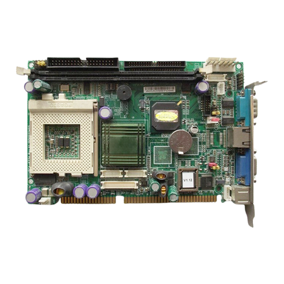
1.4 Board layout: dimensions Figure 1.1: Board layout: dimensions (component side) Chapter 1... -
Page 18: Figure 1.2:Board Layout: Dimensions (Solder Side)
Figure 1.2: Board layout: dimensions (solder side) PCA-6774 User Manual... - Page 19 Installation This chapter explains the setup procedures of PCA-6774 hardware, including instruc- tions on setting jumpers and connecting peripherals, switches and indicators. Be sure to read all safety precautions before you begin the installation procedure. Chapter 2...
-
Page 20: Chapter 2 Installation
Chapter 2 Installation 2.1 Jumpers The PCA-6774 has a number of jumpers that allow you to configure your system to suit your application. The table below lists the functions of the various jumpers. Table 2.1: Jumpers Label Function CMOS clear... - Page 21 Table 2.2: Connectors CN12 External Keyboard Connector CN14 CPU FAN Connector CN15 EBX Power Connector CN16 Power LED & Keyboard Lock CN17 External Speaker CN18 Reset Connector CN19 HDD LED Connector CN20 ATX Feature Connector CN21 ATX Soft-on Power Button Connector CN22 LCD 40-Pin Connector CN23...
-
Page 22: Locating Connectors (Component Side)
2.3 Locating Connectors (component side) Figure 2.1: Jumper & Connector locations PCA-6774 User Manual... -
Page 23: Locating Connectors (Solder Side)
2.4 Locating Connectors (solder side) Figure 2.2: Connectors (solder side) 2.5 Setting Jumpers You may configure your card to match the needs of your application by setting jumpers. A jumper is a metal bridge used to close an electric cir- cuit. - Page 24 A pair of needle-nose pliers may be helpful when working with jumpers. If you have any doubts about the best hardware configuration for your application, contact your local distributor or sales representative before you make any changes. Generally, you simply need a standard cable to make most connections. PCA-6774 User Manual...
-
Page 25: Clear Cmos (J1)
2.6 Clear CMOS (J1) Warning! To avoid damaging the computer, always turn off the power supply before setting “Clear CMOS.” Before turning on the power supply, set the jumper back to “3.0 V Battery On.” This jumper is used to erase CMOS data and reset system BIOS informa- tion. -
Page 26: Com2 Rs232-422-485 Select (J3)
When the watchdog timer activates (CPU processing has come to a halt), it can reset the system or generate an interrupt on IRQ11. This can be set via setting J2 as shown below: Table 2.5: Watchdog timer output option (J2) *System reset IRQ 11 * default setting PCA-6774 User Manual... -
Page 27: Installing Dimms
2.9 Installing DIMMs The procedure for installing DIMMs is described below. Please follow these steps carefully. The number of pins are different on either side of the breaks, so the module can only fit in one way. DIMM modules have different pin contacts on each side, and therefore have a higher pin den- sity. -
Page 28: Atx Power Control Connector (Cn20,Cn21)
2.10.1 ATX feature connector (CN20) and soft-on power button connector (CN21) The PCA-6774 can support an advanced soft power switch function, if an ATX power supply is used. To enable the soft power switch function: Get the specially designed ATX-to-EBX power cable (PCA-6774 optional item, Part No. -
Page 29: Printer Port Connector (Cn4)
BIOS settings. 2.13 Floppy drive connector (CN3) You can attach up to two floppy drives to the PCA-6774’s on-board con- troller. You can use any combination of 5.25” (360 KB and 1.2 MB) and/ or 3.5” (720 KB, 1.44 MB, and 2.88 MB) drives. -
Page 30: Ide Connector (Cn1,Cn2)
Appendix B. 2.14 IDE connector (CN1,CN2) The PCA-6774 provides an IDE channel to which you can attach up to two Enhanced Integrated Device Electronics hard disk drives or CDROM to the PCA-6774’s internal controller. The PCA-6774's IDE controller uses a PCI interface. -
Page 31: Vga/Lcd Interface Connections
CN22 consists of a 40-pin connector which can support an 18-bit LCD panel. It is Hirose’s product no. DF13A-40DP-1.25 V. The PCA-6774 provides a bias control signal on CN22 that can be used to control the LCD bias voltage. It is recommended that the LCD bias volt- age not be applied to the panel until the logic supply voltage (+5 V or +3.3 V) and panel video signals are stable. -
Page 32: Panel Type Selection (Sw1)
* Default setting ** will support in the future 2.16 USB connectors (CN6) The PCA-6774 board provides up to two USB (Universal Serial Bus) ports. This gives complete Plug and Play, and hot attach/detach for up to PCA-6774 User Manual... -
Page 33: Ethernet Configuration
CD disc. 2.18 Power connectors (CN14, CN15) 2.18.1 Main power connector, +5 V, +12 V (CN15) Supplies main power to the PCA-6774 (+5 V), and to devices that require +12 V. 2.18.2 CPU Fan power supply connector (CN14) Provides power supply to CPU cooling fan. Only present when +12 V power is supplied to the board. -
Page 34: Atx Power & Hdd Led, Speaker Out Connector
(CN16, CN17, CN19) Next, you may want to install external switches to monitor and control the PCA-6774. These features are optional: install them only if you need them. CN16, CN17, CN19 integrated in one connector, which is an 5 x 3 pin header, 180degree, male. -
Page 35: Watchdog Output (Cn18)
It provides connection for watchdog output, detailed pin assignment refer to Appendix B. 2.24 Daughter card connector (CN27,CN28) CN27, CN28 are 20-pin 180degree female connectors.With daughter board, PCA-6774 can support 2 LAN and 4 USB ports. Detailed pin defi- nition you will find in Appendix B. Chapter 2... - Page 36 PCA-6774 User Manual...
- Page 37 Software Configuration This chapter details the software con- figuration information. It shows you how to configure the card to match your application requirements. Award System BIOS will be covered in Chapter 4. Sections include: • Introduction • VGA display software configuration...
-
Page 38: Chapter 3 Software Configuration
Ensure that the AWD- FLASH.EXE and *.BIN files are located in the working drive. NOTE: Ensure that you do not run AWDFLASH.EXE while your system is operating in EMM386 mode. PCA-6774 User Manual... -
Page 39: Figure 3.1:Vga Setup Screen
At the prompt, type AWDFLASH.EXE and press <Enter>. The VGA configuration program will then display the following: Figure 3.1: VGA setup screen At the prompt, enter the new BIN file which supports your display. When you are sure that you have entered the file name correctly press <Enter>. - Page 40 PCA-6774 User Manual...
-
Page 41: Award Bios Setup
Chapter 4 Ducks that Need Love! Award BIOS Setup This chapter describes how to set BIOS configuration data. Chapter 4... -
Page 42: Chapter 4 Award Bios Setup
The CMOS memory has lost power and the configuration informa- tion has been erased. The PCA-6774 Series' CMOS memory has an integral lithium battery backup. The battery backup should last ten years in normal service, but when it finally runs down, you will need to replace the complete unit. -
Page 43: Award Bios Setup
4.2 Award BIOS setup Award’s BIOS ROM has a built-in Setup program that allows users to modify the basic system configuration. This type of information is stored in battery-backed CMOS RAM so that it retains the Setup information when the power is turned off. 4.2.1 Entering setup Power on the computer and press <Del>... -
Page 44: Standard Cmos Features Setup
Setup Menu allows users to configure system components such as date, time, hard disk drive, floppy drive and display. Once a field is high- lighted, on-line help information is displayed in the left bottom of the Menu screen. Figure 4.2: CMOS Features setup PCA-6774 User Manual... -
Page 45: Advanced Bios Features Setup
4.2.3 Advanced BIOS Features setup By choosing the Advanced BIOS Features Setup option from the Initial Setup Screen menu, the screen below is displayed. This sample screen contains the manufacturer’s default values for the PCA-6774 Series. Figure 4.3: Advanced BIOS Features setup Chapter 4... -
Page 46: Advanced Chipset Features Setup
4.2.4 Advanced Chipset Features setup By choosing the Advanced Chipset Features option from the Initial Setup Screen menu, the screen below is displayed. This sample screen contains the manufacturer’s default values for the PCA-6774 Series. Figure 4.4: Advanced Chipset Features setup PCA-6774 User Manual... -
Page 47: Integrated Peripherals
4.2.6 Power Management Setup By choosing the Power Management Setup option from the Initial Setup Screen menu, the screen below is displayed. This sample screen contains the manufacturer’s default values for the PCA-6774 Series. Figure 4.6: Power Management Setup Chapter 4... -
Page 48: Pca-6774 User Manual
4.2.7 PnP/PCI Configurations By choosing the PnP/PCI Configurations option from the Initial Setup Screen menu, the screen below is displayed. This sample screen contains the manufacturer’s default values for the PCA-6774 Series. Figure 4.7: PnP/PCI Configurations 4.2.8 PC Health Status The PC Health Status option displays information such as CPU and moth- erboard temperatures, fan speeds, and core voltage. -
Page 49: Frequency/Voltage Control
4.2.9 Frequency/Voltage Control By choosing the Frequency/Voltage Control option from the Initial Setup Screen menu, the screen below is displayed. This sample screen contains the manufacturer’s default values for the PCA-6774 Figure 4.9: Frequency/Voltage Control Caution Incorrect settings in Frequency/Voltage Control may damage the system CPU, video adapter, or other hardware. -
Page 50: Load Optimized Defaults
ROM. If the stored record created by the Setup program should ever become corrupted (and therefore unusable), these defaults will load auto- matically when you turn the PCA-6774 Series system on. Figure 4.10: Load BIOS defaults screen 4.2.11 Set Password... -
Page 51: Save & Exit Setup
At the “Confirm Password” prompt, retype the desired password, then press <Enter>. Select Save to CMOS and EXIT, type <Y>, then <Enter>. To Change Password Choose the Set Password option from the CMOS Setup Utility main menu and press <Enter>. When you see “Enter Password”... -
Page 52: Exit Without Saving
4.2.13 Exit Without Saving Selecting this option and pressing <Enter> lets you exit the Setup pro- gram without recording any new values or changing old ones. PCA-6774 User Manual... - Page 53 PCI SVGA Setup Introduction Installation of SVGA drivers -for Windows 95/98/Me -for Windows NT/2000/XP Further information...
-
Page 54: Chapter 5 Pci Svga Setup
The system is initially set to simultaneous display mode. If you want to enable the CRT display only or the flat panel display only, please contact VIA Technology Inc., or our sales representative for detailed information. PCA-6774 User Manual... -
Page 55: Installation Of The Svga Driver
5.2 Installation of the SVGA Driver Complete the following steps to install the SVGA driver. Follow the pro- cedures in the flow chart that apply to the operating system that you are using within your board. Notes: 1. The windows illustrations in this chapter are intended as examples only. - Page 56 Choose the "Adapter" tab, then press the "Change..." button. Press the "Have Disk" button. PCA-6774 User Manual...
- Page 57 Type in the path: D:\Biscuit\9577\VGA\Win9x_Me 9577 Select the highlighted item, and click the "OK" button. Chapter 5...
- Page 58 "S3 GraphicsTwister" appears under the adapter tab. Click the "Apply" button, then the "OK" button. Press “Yes” to reboot. PCA-6774 User Manual...
-
Page 59: Installation For Windows 98/Me
5.2.2 Installation for Windows 98/Me Select "Start", "Settings", "Control Panel", "Display", and "Set- tings," then press the "Advanced..." button. Chapter 5... - Page 60 Select “Adapter,” then “Change.” PCA-6774 User Manual...
- Page 61 Press “Next,” then “Display a list..” Press the “Have disk...” button. Chapter 5...
- Page 62 Insert the CD into the CD-ROM drive. Type in the path D:\Biscuit\9577\VGA\Win9x_Me Then press “OK” 9577 Select the highlighted item, then click “OK.” PCA-6774 User Manual...
- Page 63 "S3 Graphics Twister" appears under the adapter tab. Click the "Apply" button. Press “Yes” to reboot. Chapter 5...
-
Page 64: Installation For Windows Nt
5.2.3 Installation for Windows NT Note: Service Pack X (X = 3, 4, 5, 6,...) must be installed first, before you install the Windows NT VGA driver. Select "Start", "Settings", "Control Panel" and double click the "Display" icon. PCA-6774 User Manual... - Page 65 Choose the "Settings" tab, and press the "Display Type" button. Chapter 5...
- Page 66 Press the "Change..." button. PCA-6774 User Manual...
- Page 67 Click the "Have Disk..." button. Type the path: D:\Biscuit\VGA\WinNT Press the "OK" button. Chapter 5...
- Page 68 Select the highlighted item, and click the "OK" button. Press "Yes" to proceed. Press "OK" to reboot. PCA-6774 User Manual...
-
Page 69: Installation For Windows 2000
5.2.4 Installation for Windows 2000 Select "System", "Settings", "Control Panel" and double click the "system" icon. Chapter 5... - Page 70 Choose the "Video Controller (VGA Compatible)” button. PCA-6774 User Manual...
- Page 71 Choose the "Drive" button, press “Update Driver...” button. Chapter 5...
- Page 72 Choose "Display a list of...", then press “Next” button. Choose “Display adapters”, press “Next” button. PCA-6774 User Manual...
- Page 73 Click the “Have Disk” button. Type the path D:\Biscuit\9577\VGA\Win2000 press the “OK” but- ton. Chapter 5...
-
Page 74: Installation For Windows Xp
Press “Finish" to reboot. 5.2.5 Installation for Windows XP Select "System", "Settings", "Control Panel" and double click the "system" icon. PCA-6774 User Manual... - Page 75 Choose “Hardware” and “Device Manager”, press “OK” button. Chapter 5...
- Page 76 Choose “Video Controller (VGA Compatible), press “OK” button. PCA-6774 User Manual...
- Page 77 Choose "Driver”, “Update Driver”, press “OK” button. Choose “Install from a list..”, press “Next”. Chapter 5...
- Page 78 Choose “Don’t search. I will..”, press “Next” button. Choose “Display adapters”, press “Next” button. PCA-6774 User Manual...
- Page 79 Type the path D:\Biscuit\9577\VGA\WinXP then press “OK” but- ton. 9577 Choose “S3 Graphics Twister + S3 Hotkey” then press “Next” but- ton. Chapter 5...
-
Page 80: Further Information
Press “Finish" to reboot. 5.3 Further Information For further information about the AGP/VGA installation in your PCA- 6774, including driver updates, troubleshooting guides and FAQ lists, visit the following web resources: VIA website: www.via.com.tw Advantech websites: www.advantech.com www.advantech.com.tw PCA-6774 User Manual... - Page 81 PCI Bus Ethernet Inter- face This chapter provides information on Ethernet configuration. • Introduction • Installation of Ethernet drivers for Windows 98/2000/NT • Further information...
-
Page 82: Chapter 6 Pci Bus Ethernet Interface
For example, MS-NT, IBM-LAN server, and so on. Then choose the correct driver to install in your biscuit PC. The installation procedures for various servers can be found on the sup- plied CD-ROM, the correct path being: D:\Biscuit\9577\LAN\82559er\wfw311 PCA-6774 User Manual... -
Page 83: Installation For Windows 98
6.2.2 Installation for Windows 98 a. Select "Start", "Settings". "Control Panel". b. Double click "Network". a. Click "Add" and prepare to install network functions. Chapter 6... - Page 84 Select the "Adapter" item to add the Ethernet card. a. Click "Have Disk" to install the driver. a. Insert the CD into the D: drive b. Fill in "D:\Biscuit\9577\LAN\” c. Click "OK" PCA-6774 User Manual...
- Page 85 a. Choose the "Intel 8255x based PCI Ethernet Adapter (10/100)" b. Click "OK". a. Make sure the configurations of relative items are set correctly. b. Click "OK" to reboot. Chapter 6...
-
Page 86: Installation For Windows 2000
6.2.3 Installation for Windows 2000 Open Device Manager, PCA-6774 User Manual... - Page 87 Click “Update Driver...” Chapter 6...
- Page 88 Click “Next” Select “Network Adapter”, and click “Next” PCA-6774 User Manual...
- Page 89 Select the driver, and click “Next” Click “OK” Chapter 6...
- Page 90 Click “Next” Click “Finish” PCA-6774 User Manual...
-
Page 91: Installation For Windows Nt
Click “Yes” to reboot 6.2.4 Installation for Windows NT a. Select "Start", "Settings", "Control Panel" b. Double click "Network" Chapter 6... - Page 92 Choose type of network. b. Click "Next" a. Click "Select from list..." PCA-6774 User Manual...
- Page 93 Click “Have Disk.” a. Insert the Utility CD ROM b. Fill in the correct path: D:\Biscuit\9577\LAN\82559er\winnt4 c. Click "OK". Chapter 6...
- Page 94 Check the highlighted item, and click “OK.” PCA-6774 User Manual...
- Page 95 Click “Next” to continue setup. Choose the networking protocols, then click "Next" Chapter 6...
- Page 96 Select the correct Network Services then click "Next" Click “Next” to continue setup. PCA-6774 User Manual...
-
Page 97: Further Information
Click “Next” to start the network. 6.3 Further information Realtek website: www.realtek.com.tw Intel website: www.intel.com Advantech websites: www.advantech.com www.advantech.com.tw Chapter 6... - Page 98 PCA-6774 User Manual...
-
Page 99: Watchdog Timer
Programming the Watchdog Timer The board is equipped with a watchdog timer that resets the CPU or generates an interrupt if processing comes to a standstill for any reason. This feature ensures system reliability in industrial standalone or unmanned environments. -
Page 100: Appendix A Programming The Watchdog Timer
After data entry, your program must refresh the watchdog timer by rewriting the I/O port 443 (hex) while simultaneously setting it. When you want to disable the watchdog timer, your program should read I/O port 443 (hex). PCA-6774 User Manual... - Page 101 The following example shows how you might program the watchdog timer in BASIC: REM Watchdog timer example program OUT &H443, data REM Start and restart the watchdog GOSUB 1000 REM Your application task #1 OUT &H443, data REM Reset the timer GOSUB 2000 REM Your application task #2 OUT &H443, data...
- Page 102 PCA-6774 User Manual...
-
Page 103: Pin Assignments
Pin Assignments This appendix contains information of a detailed or specialized nature. It includes: • Primary IDE Connector • Secondary IDE Connector • Floppy Connector • Printer Port Connector • CompactFlash Socket • USB Port 1, 2 • D-SUB VGA Connector •... -
Page 104: Appendix B Pin Assignments
Appendix B Pin Assignments B.1 Primary IDE Connector (CN1) Table B.1: Primary IDE Connector (CN1) Signal Signal IDE RESET READY Cable Select (Pull-Low) DACK IRQ14 Cable check Active LED PCA-6774 User Manual... -
Page 105: Secondary Ide Connector (Cn2)
B.2 Secondary IDE Connector (CN2) Table B.2: Secondary IDE Connector(CN2) Signal Signal RESET DREQ IOCHRDY CSELS DACK DMA66 Detect HDCS0 HDCS1 HDLED Appendix B... -
Page 106: Floppy Connector (Cn3)
Table B.3: Floppy Connector (CN3) Signal Signal REDWC INDEX MOTOR A ON DISKETTE DRIVE SELECT B CHANGE HEAD SELECT DRIVE SELECT A READ DATA MOTOR B ON WRITE PRO- DIRECTION TECT SELECT TRACK 00 STEP WRITE GATE WRITE DATA PCA-6774 User Manual... -
Page 107: Printer Port Connector (Cn4)
B.4 Printer Port Connector (CN4) Table B.4: Printer Port Connector (CN4) Signal Signal AFD* INIT* SLIN* ACK* BUSY SLCT * low active Appendix B... -
Page 108: Compactflash Socket (Cn5)
B.5 CompactFlash Socket (CN5) Table B.5: CompactFlash Socket (CN5) Signal Signal #CD1 #CE2 #VS14 #IORD #IOWR #IRQ #CSEL #VS2 RESET #WAIT #INPACK #REG BVD2 BVD1 IOCS16 #CD2 PCA-6774 User Manual... -
Page 109: Usb Connector (Cn6)
B.6 USB Connector (CN6) Table B.6: USB Connector (CN6) Signal Signal UVO- UV1- UVO+ UV1+ USB GND USB GND Appendix B... -
Page 110: D-Sub Vga Connector (Cn7)
B.7 D-SUB VGA Connector (CN7) Table B.7: D-SUB VGA Connector (CN7) Signal Signal GREEN CRT Vcc BLUE DDCDATA HSYNC VSYNC DDCCLOCK B.8 LAN RJ45 Connector (CN8) Table B.8: LAN RJ45 Connector (CN8) Signal PCA-6774 User Manual... -
Page 111: Com Port 1, 2 Connector (Cn9, Cn10)
B.9 COM Port 1, 2 Connector (CN9, CN10) Table B.9: COM Port 1 Connector (CN9, CN10) COM1 connector (CN9) COM2 connector (CN10) RS232 Only Signal Signal Signal Signal 1 DCD 6 DSR 1 DCD 2 DSR 2 RX 7 RTS 3 RX 4 RTS 3 TX... -
Page 112: External Keyboard Connector (Cn12)
B.11 External Keyboard Connector (CN12) Table B.11: External Keyboard Connector (CN12) Signal Keyboard Clock Keyboard Data B.12 CPU Fan Connector (CN14) Table B.12: CPU FAN Connector (CN14) Signal +12V Fan speed detect signal input PCA-6774 User Manual... -
Page 113: Ebx Power Connector (Cn15)
B.13 EBX Power Connector (CN15) Table B.13: EBX Power Connector (CN15) Signal +5V input +12V input +5V input Appendix B... -
Page 114: Power Led & Keyboard Lock (Cn16)
B.14 Power LED & Keyboard Lock (CN16) Table B.14: Power LED & Keyboard Lock (CN16) Signal Power LED+ Power LED- KB_LOCK+ KB_LOCK-(GND) B.15 External Speaker (CN17) Table B.15: External Speaker (CN17) Signal Internal Buzzer Speaker Signal PCA-6774 User Manual... -
Page 115: Reset Connector (Cn18)
B.16 Reset Connector (CN18) Table B.16: Reset Connector (CN18) Signal Reset signal B.17 HDD LED Connector (CN19) Table B.17: HDD LED Connector (CN19) Signal HDD LED+ HDD LED- Appendix B... -
Page 116: Atx Feature Connector (Cn20)
B.18 ATX Feature Connector (CN20) Table B.18: ATX Feature Connector (CN20) Signal ATX PS_ON signal output Suspend 5V input B.19 ATX Soft-on Power Button Connector (CN21) Table B.19: ATX Soft-on Power Button Connector (CN21) Signal POWER ON PCA-6774 User Manual... -
Page 117: Lcd 40-Pin Connector (Cn22)
B.20 LCD 40-Pin Connector (CN22) Table B.20: LCD 40-Pin Connector (CN22) Signal Signal +5V output +5V output +3.3V output +3.3V output PD0 signal output PD1 signal output PD2 signal output PD3 signal output PD4 signal output PD5 signal output PD6 signal output PD7 signal output PD8 signal output PD9 signal output... -
Page 118: Lcd 20-Pin Connector (Cn23)
Table B.21: LCD 20-Pin Connector (CN23) Signal Signal PD24 PD25 PD26 PD27 PD28 PD29 PD30 PD31 PD32 PD33 PD34 PD35 B.22 LCD Backlight Connector (CN24) Table B.22: LCD Backlight Connector (CN24) Signal +12V output Back-light enable signal output PCA-6774 User Manual... -
Page 119: Lvds Connector (Cn25)
B.23 LVDS Connector (CN25) Table B.23: LVDS Connector (CN25) Signal Signal 3V_SAFE 3V_SAFE Appendix B... -
Page 120: I/O Daughter Board Connector 1 (Cn27)
B.24 I/O Daughter Board Connector 1 (CN27) Table B.24: I/O Daughter Board Connector 1 (CN27) Signal Signal USBD3+ USBD2+ USBD3- USBD32 USBV2 USBV2 USBD1+ USB0+ USB1- USB0- USBV0 USBV0 3V3B LAN2 ACT LED+ LAN2 ACT LED- LAN SPLED PCA-6774 User Manual... -
Page 121: I/O Daughter Board Connector 2 (Cn28)
B.25 I/O Daughter Board Connector 2 (CN28) Table B.25: I/O Daughter Board Connector 2 (CN28) Signal Signal LAN2 TD+ LAN2 RD+ LAN2 TD- 3V3B LAN2 RD- MSCLK B.26 RS485/422 Connector (CN29) Table B.26: RS485/422 Connector (CN29) Description Description TXD- TXD+ RXD- RXD+ Appendix B... -
Page 122: Pca-6774 User Manual
PCA-6774 User Manual... -
Page 123: System Assignments
System Assignments This appendix contains information of a detailed nature. It includes: • System I/O ports • 1st MB memory map • DMA channel assignments • Interrupt assignments Appx. C... -
Page 124: Appendix C System Assignments
100-CF7 -available for system use* CF8-CFB PCI Configuration Address CFC-CFF PCI Configuration Data D00-FFFF -available for system use- 200-20F Game Port 2F8-2FF COM2 378-37F Parallel Port (Standard & AFF) 3F0-3F1 Configuration Index/Data 3F0-3F7 Floppy Controller 3F8-3FF COM1 PCA-6774 User Manual... -
Page 125: 1St Mb Memory Map
Table C.1: System I/O ports Addr. range (Hex) Device 778-77A Parallel Port (ECP Extensions) (Port 378+400) MPU-401 select from 300 ~ 330H (2 bytes) C.2 1st MB memory map Table C.2: 1st MB memory map Addr. range (Hex) Device F0000h - FFFFFh System ROM *CC000h - EFFFFh Unused (reserved for Ethernet ROM) -
Page 126: Dma Channel Assignments
Function Available Available (audio) Floppy disk (8-bit transfer) Available (parallel port) Cascade for DMA controller 1 Available Available Available * Audio DMA select 1, 3, or 5 ** Parallel port DMA select 1 (LPT2) or 3 (LPT1) PCA-6774 User Manual... -
Page 127: Interrupt Assignments
C.4 Interrupt assignments Table C.4: Interrupt assignments Interrupt# Interrupt source IRQ 0 Interval timer IRQ 1 Keyboard IRQ 2 Interrupt from controller 2 (cascade) IRQ 3 COM2 IRQ 4 COM1 IRQ 5 Unused IRQ 6 IRQ 7 LPT1 IRQ 8 IRQ 9 Reserved (audio) IRQ 10... - Page 128 PCA-6774 User Manual...
Need help?
Do you have a question about the PCA-6774 and is the answer not in the manual?
Questions and answers