Table of Contents
Advertisement
Quick Links
Download this manual
See also:
User Manual
Advertisement
Table of Contents

Related Manuals for Dedicated Micros CamVu 2000


Summary of Contents for Dedicated Micros CamVu 2000
- Page 1 CamVu 2000 Installation and Operation Manual...
-
Page 2: Table Of Contents
Unit Operation ..................92 Operating the Viewer ................92 Whilst every attempt is made to ensure these manuals are accurate and current, Dedicated Micros reserve the right to alter or modify the specification of the machine described herein without prejudice. Dedicated Micros ©2010... -
Page 3: Introduction
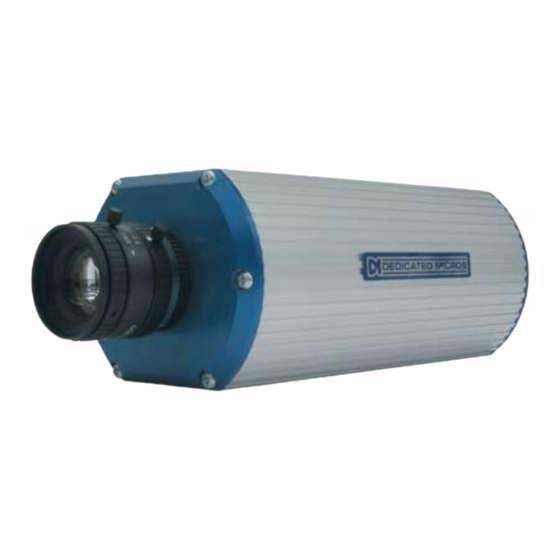
Introduction 1.03 Offering up to six times the definition of analogue cameras, the Dedicated Micros CamVu 2000 Camera is ideal for situations where high resolution, high quality images are required. The camera’s high definition technology is based on Dedicated Micros award winning NetVu Connected architecture, allowing seamless... - Page 4 “Declaration of Conformity” is held at Dedicated Micros Ltd, 1200 Daresbury Park, Daresbury, Cheshire WA4 4HS www.dedicatedmicros.com Hereby, Dedicated Micros LTD, declares that this CamVu 2000 Camera is in compliance with the essential requirements and other relevant provisions of Directive 95/5/EC.
-
Page 5: Important Safeguards
EN 60950 Safety of IT and similar equipment. • EN 55022 Class A. Radiated Emissions Standard, suitable for Commercial or Residential use Further details about these applicable standards can be obtained from Dedicated Micros Ltd., 1200 Daresbury Park, Daresbury, Cheshire WA4 4HS 1.01002 RF Interference warning This is a class A product. -
Page 6: Power Sources
POE Injector The Dedicated Micros POE Injector is designed to enable the use of POE (Power over Ethernet) before a POE capable switch has been installed. It is installed alongside a suitable 48Vdc PSU that can supply 15W is required - DM/PSU/48V can be purchased separately from Dedicated Micros. - Page 7 Layer 3 Enhanced Switch shown, normal Ethernet switch or DVR/ NVR connection also compatible. POE Injector Power Supply specification Adaptor socket - 5.5mm diameter with a 2.1mm central circular pin +48V goes to the centre pin of the power connector - 0V to the outside barrel Draft Dedicated Micros ©2010...
-
Page 8: Rear Connections
Connections The CamVu 2000 features push fit connectors which house connections for 12VDC power and the relay output. There are also connections for an audio input (via 3.5mm stereo jack socket) and an RJ45 socket for Draft connection to a suitable network point and POE. Serial communications with camera is via the D type plug. -
Page 9: Overview
5.13 Step 3 - Connecting Video The CamVu 2000 has a 75Ω BNC connector configurable for PAL or NTSC which can be used to focus the lens during installation. The video feed is also sent via the network connection. Step 4 - Connecting Alarms The CamVu 2000 supports two EOL (End Of Line) alarm inputs, these are located on the push fit connector. - Page 10 If the device utilises POE, this step would not be necessary. Connect the Network connector at this stage, refer to ‘Power over Ethernet’ for details on available POE Injector. The CamVu 2000 is supplied by a two way 3.81mm pitch screw terminal push fit connector, separate to the alarm connector.
-
Page 11: Configuring The Unit
If subsequently the unit is assigned a fixed IP address, its DNS address can no longer be used Note: The unit’s DNS address can be changed subsequently to something more memorable or meaningful than its serial number by editing the System name option in the System configuration page. Dedicated Micros ©2010... - Page 12 If prompted, enter a username and password. The default settings are; username:dm and password:web. The Main Menu page will be displayed. 6.13 The configuration menus are accessible via the link on the left hand side of the page. Dedicated Micros ©2010...
-
Page 13: System
Email reporting and control of the display resolution. The Maintain page allows the current configuration to be saved, and for previously saved settings to be loaded. The PowerScript management pages allows individual PowerScripts to be disabled if required. Dedicated Micros ©2010... -
Page 14: Attributes
This is the IP address of the default gateway (router) assigned by the DHCP server. Number of Cameras Shows the number of camera channels on the unit i.e 1 Global PPS Details the unit Global PPS (Pictures Per Second) recording rate. Dedicated Micros ©2010... - Page 15 Links to the System Settings->Software details page Time/Date (Green) Links to the System->Time and Date page Accounts (Yellow) Links to the Viewer Settings->User Accounts details page Network (Blue) Links to the Network Settings->Network details page Refresh (Purple) Refreshes the current page Draft Dedicated Micros ©2010...
-
Page 16: Software
Software This page details the installed software and may be needed if calling Technical Support. Draft System (Red) Links back to the System Setttings page Diagnostics (Blue) Opens the Status->Diagnostics page. Refresh (Purple) Refreshes the current page Dedicated Micros ©2010... -
Page 17: Status
Opens the General Information page (refer to ‘General Information’). Record Details Opens the Record Details page (refer to ‘Record Details’). Camconfig Details Opens the Camconfig Details page (refer to ‘Camconfig Details’). Refresh (Purple) Refreshes the current page Dedicated Micros ©2010... - Page 18 General Information Draft Diagnostics (Blue) Opens the Diagnostics page Refresh (Purple) Refreshes the current page Dedicated Micros ©2010...
- Page 19 Details Draft Diagnostics (Blue) Opens the Diagnostics page Refresh (Purple) Refreshes the current page Dedicated Micros ©2010...
- Page 20 Camconfig Details Draft Diagnostics (Blue) Opens the Diagnostics page Refresh (Purple) Refreshes the current page Dedicated Micros ©2010...
-
Page 21: Unit Status
Reset code The last reset code used is displayed. Restart reason The reason for the last restart is displayed i.e. Controlled User Reset. Alarm Status(Yellow) Opens the Alarm Status page (below) Refresh (Purple) Refreshes the current page Dedicated Micros ©2010... -
Page 22: Alarm Status
Alarm Contacts/Zones/Relay Outputs Alarm Contacts, Alarm Zones and Relay Outputs that are in an ‘active’ state are shown light green. ‘In-active’ ones appear dark green (not illuminated). Alarms(Blue) Opens the Alarm Status page (below) Refresh (Purple) Refreshes the current page Dedicated Micros ©2010... -
Page 23: Language
A server reboot will be required to implement system language changes. The unit can be rebooted via System Settings->Maintain->Reset. Session Language Select to change the language settings for the current session only. Choose Select to immediately activate session language changes. Reset(Red) Resets the unit Refresh (Purple) Refreshes the current page Dedicated Micros ©2010... -
Page 24: Time And Date
Displays the system time of the PC currently being used to view the webpages. Sync Time (Blue) Use this button to synchronise the time of the unit to that of the PC being used to view the webpages. Dedicated Micros ©2010... - Page 25 Note: The PC Time and Sync Time options will only be available if viewing the menu via the webpages. System (Yellow) Opens the System Settings->System page Refresh (Purple) Refreshes the current page Draft Dedicated Micros ©2010...
-
Page 26: Serial Ports
Baud/Parity/Data/Stop/Flow Control These options allow the Serial port communication settings to be configured. Note: These settings will default to pre-determined values and should not normally be altered. Reset(Red) Resets the unit Maintain (Green) Opens the System Settings->Maintain page Refresh (Purple) Refreshes the current page Dedicated Micros ©2010... -
Page 27: Audio
Record uncompressed Select this option to record audio in an uncompressed format. Note: Recording in uncompressed format will significantly increase the disk space used. Reset(Red) Resets the unit Refresh (Purple) Refreshes the current page Dedicated Micros ©2010... -
Page 28: Features
When de-selected here, the ‘Masked Camera Detection’ menu will no longer be displayed in the menu tree. Camera Masking Remote Reporting Select this option to activate the Remote Reporting function, refer to ‘Network Settings-Remote Reporting’ for more information. Dedicated Micros ©2010... -
Page 29: System Features Network
8000 if the default web port (80) is blocked by the network or firewall. Use Record Profiles for Tx For Tx Select this option when units required Video Transmission profile (rate/quality/resolution) is identical to that being recorded. Dedicated Micros ©2010... -
Page 30: System Features Video
Disable Transcoding Transcoding reduces the size of images to be transmitted across a network whilst recording the original higher resolution image. This reduces network traffic but increases the overhead on the unit. Partial full Duplex Dedicated Micros ©2010... -
Page 31: System Features Other
When de-selected here, the ‘Event Search’ menu will no longer be displayed in the menu tree. Enable RVRC page Select this option to activate the RVRC Remote Set/Unset/Override function, refer to ‘Record Settings-RVRC’ for more information. Note: When de-selected here, the ‘RVRC’ menu will no longer be displayed in the menu tree. Dedicated Micros ©2010... -
Page 32: Maintain
USB device. Current unit settings can also be saved for future use and previously saved settings restored. Draft Server Reset (Red) Select to restart the unit. Configuration Default (Green) Select to return the unit to its factory default settings and restart. Dedicated Micros ©2010... -
Page 33: Powerscript Management
Clicking Save will alter DEFAULT.C, if you already have a custom PowerScript on your unit which uses the DEFAULT.C file, please contact your regional Technical Support before using this page. Draft Reset(Red) Resets the unit Save (Green) Saves the current settings Refresh (Purple) Refreshes the current page Dedicated Micros ©2010... -
Page 34: Display
The Viewer Defaults page allows the Viewer menu settings to be configured. The User Accounts page helps protect configuration procedures by limiting access to specific users via accounts and passwords. Draft Dedicated Micros ©2010... -
Page 35: Viewer Defaults
For example, if a local unit and a remote DVR are to be accessed, it is possible to set the Applet location for both DVRs as the local unit. If viewing the unit remotely, Dedicated Micros provide a remote applet located on the Dedicated Micros website (www.dedicatedmicros. - Page 36 Set Location Select the applet location. Choose from ‘Default location’ i.e. the applet installed on the unit; or the ‘Dedicated Micros website’ option i.e. the remote applet. Reset (Red) This button will restart the unit. Refresh (Purple) Refreshes the current page Draft Dedicated Micros ©2010...
-
Page 37: User Accounts
FTP connection. ● Default username:none Default Password:none. telnet Assigning username and password requirements for Telnet connections will limit Telnet access to the unit (Telnet can be used to upgrade the unit). ● Default Username:dm Default Password:none. Dedicated Micros ©2010... - Page 38 Modify (Green) To modify a user’s settings, highlight the user in the list and press Modify. Delete (Yellow) To delete a user’s settings, highlight the user in the list and press Delete. Dedicated Micros ©2010...
-
Page 39: Camera
Camera The Camera menu page allows configuration of the camera setup. Refer to the individual menus for further details. The Camera page allows the quick configuration the camera setup. Draft Dedicated Micros ©2010... -
Page 40: Camera Setup
This sets the maximum image resolution that is collected by the camera. If full 1600x1200 resolution (UXGA) is not required, reducing the collection resolution can increase the capture rate of the camera. By default collection resolution is set to Refresh (Purple) Refreshes the current page Dedicated Micros ©2010... -
Page 41: Icr Settings
The AoE Setup page allows configuration of the units ATA over Ethernet (AoE) function. AoE is a network protocol designed for simple high-performance access of storage devices over Ethernet networks Importantly the external storage device must be located on the same network as the unit. Dedicated Micros ©2010... -
Page 42: Default
Normal Rate-JPEG 1pps or Normal Rate-MultiMode recording. Record Duration/Enhance Quality The recording duration can be limited to a set number of days; allowing the recording quality to be enhanced for a shorter storage period. Refresh (Purple) Refreshes the current page. Dedicated Micros ©2010... -
Page 43: Profile Record
Unset/Set/Override Normal Shows the recording profile used by the camera if no Timer Functions are applied and the camera is operating under Normal (non Event) conditions. Refer to the ‘Schedules’ section for further details. Dedicated Micros ©2010... - Page 44 Select from Maximum, Very High, High, Medium, or Low. Select User Defined to use settings established in the Advance Profile Record menu. Note: The higher the Quality setting, the greater the storage space needed. Draft Refresh (Purple) Refreshes the current page Dedicated Micros ©2010...
-
Page 45: Advanced Record
Select image resolution format (QCIF, CIF, 2CIF or 4CIF). rate_kbps If MPEG4 is selected, the figure entered here will be the bit rate allocated. A higher bit rate will provide better quality. MPEG bit rates can be entered within the range of 45-2500K bits/second. Dedicated Micros ©2010... - Page 46 Select the number of pictures recorded per second. If using MPEG4 recording, select the number of images recorded within a GOP (Group of Pictures). A GOP consists of an I-Frame (keyframe) and following P frames. Refresh (Purple) Refreshes the current page. Draft Dedicated Micros ©2010...
-
Page 47: Schedule
Draft Mode/Title Enables a name to be entered for Unset, Set and Override mode. Current Mode Shows the current timer mode according to the names entered in the Mode/title text boxes. Refresh (Purple) Refreshes the current page. Dedicated Micros ©2010... -
Page 48: Rvrc
Enter Your Name Enter your recognised user name. This will be logged. Force UNSET(Green) Select to switch to Unset mode. Force SET (Yellow) Select to switch to Set mode. Force OVERRIDE (Blue) Select to switch to Override mode. Dedicated Micros ©2010... -
Page 49: Protect Video
This will refresh the video list according to the selections made in the Start Time/Date and End Time/Date dialog boxes. Select None This de-selects all the available video files. Select All This selects all the available video files. Dedicated Micros ©2010... - Page 50 Time and Date. List To Date/Time This dialog box allows a search within the protected video list to conclude at a specific Time and Date. Refresh (Purple) Refreshes the current page. Draft Dedicated Micros ©2010...
-
Page 51: Aoe Setup
They can be added to the storage capability of this unit by ‘claiming’ the storage. Unavailable storage is listed as Owned. Claimed storage capacity can be ‘released’ in the top panel. Refresh (Purple) Refreshes the current page. Dedicated Micros ©2010... -
Page 52: Alarm
The VMD Configuration page enables the unit’s VMD (Video Motion Detection) to be set-up. VMD allows a camera to automatically detect if there is any movement/changes within specific areas of the video scene. The Global Relays page allows the four onboard relay connections and global relay settings to be configured. Dedicated Micros ©2010... -
Page 53: Inputs
Enter the time in seconds for this extension. Dedicated Micros ©2010... - Page 54 Relays (Green) Opens the Alarm Settings -> Global Actions page Status (Yellow) Opens the System Settings -> Status -> Alarm Status Page Zone In (Blue) Opens the Zone Inputs page (below). Refresh (Purple) Refreshes the current page. Draft Dedicated Micros ©2010...
-
Page 55: Zone Inputs
Pre-Alarm sec This is the time period prior to the start of the alarm included with the alarm recording for archive. These images will also be protected from being overwritten. Dedicated Micros ©2010... - Page 56 Opens the Alarm Settings->Activity Setup page. Zone Act (Zone Act) Opens the Alarm Settings -> Zone Actions page. Alarm In (Alarm In) Opens the Alarm Settings -> Alarm Input Configuration page Refresh (Purple) Refreshes the current page. Dedicated Micros ©2010...
-
Page 57: Zone Actions
If this option is selected, a JPEG will be added to the reporting email (if Email Reporting is selected). Add Still Image This will record a still image of the trigger along with the standard recording. This can then be sent on to an external destination. Dedicated Micros ©2010... - Page 58 Select a zone (alarm) to configure. Primary Camera This allows a camera to be assigned as the primary camera associated with the Alarm Zone. The primary camera will be displayed when an alarm in this zone is triggered. Dedicated Micros ©2010...
-
Page 59: Masked Cam Det
Threshold Sets the level at which the alarm is generated Contrast This setting is not adjustable On Camera Masked/Unmasked Allows a Database entry to be created when the alarm is generated. Refresh (Purple) Refreshes the current page. Dedicated Micros ©2010... - Page 60 This setting is not adjustable On Mask Defines which zone will be activated when the camera is masked. On Clear Defines which zone will be activated when the camera is unmasked. Refresh (Purple) Refreshes the current page. Dedicated Micros ©2010...
-
Page 61: Vmd/Act Response Setup
Select ‘Zone’ to apply the Zone Input rules as configured in the Zone Input menu. Refer to ‘Zone Input’ for more information. Create Database Entry When selected, an alarm entry will be added to the Event database. Dedicated Micros ©2010... - Page 62 Draft Enable in OVERRIDE This will enable Activity Detection when the unit is in Weekend (Override) operation mode. Note: Unset, Set and Override modes may be renamed via Record Settings->Schedule. Refresh (Purple) Refreshes the current page. Dedicated Micros ©2010...
-
Page 63: Activity Setup
If the camera is configured to detect VMD, the following warning will be displayed. Use the Alarm Settings-> VMD/ACT Response menu option to configure ‘Detection type’ for Activity. Once Activity is configured, this page will be displayed Draft Dedicated Micros ©2010... - Page 64 This option will insert a default square of 16 x 16 cells across the displayed video image. Clear All (Yellow) This option will clear all entered cells. Edit Mode Leave as ‘Normal’. Different Edit Mode functions will be added following future development. Dedicated Micros ©2010...
-
Page 65: Vmd Configuration
If the camera are configured to detect Activity,the following warning will be displayed. Use the Alarm Settings-> VMD/ACT Response menu option to configure ‘Detection type’ for VMD. Draft Once Activity is configured, this page will be displayed Dedicated Micros ©2010... - Page 66 The default setting is 20%. Reload Img (Red) Refreshes the camera image. Clear All (Green) Removes all defined zones from the image. Default Grid (Yellow) Displays the default 16 zone grid across the whole image. Dedicated Micros ©2010...
-
Page 67: Global Actions
Recording and Not Recording. Status (Green) Opens the System Settings->Status->Unit Status page. Alarm In (Yellow) Opens the Alarm Settings->Alarm Input->Alarm Input Configuration page. Zone Act (Blue) Opens the Alarm Settings->Zone Actions->Zone Action Configuration page. Refresh (Purple) Refreshes the current page. Dedicated Micros ©2010... -
Page 68: Network
The RVRC will then be contacted following a selected event occurring i.e. reported alarm or camera failure. The Firewall page allows configuration of the onboard firewall. Draft The Connections page displays the current live connections to the unit. Dedicated Micros ©2010... -
Page 69: Network
DHCP be disabled by entering a suitable, free, static IP address. Tip: Use DHCP to locate a free IP address, then fix the unit IP address to the free one by entering the details into the IP address, subnet and gateway fields. Dedicated Micros ©2010... - Page 70 Reset Resets the unit to apply changes. Rem Report Opens the Network Settings->Remote Reporting page. Webcam Opens the Network Settings->Web Camera Configuration page. Email Opens the Network Settings->Email page. Draft Refresh (Purple) Refreshes the current page. Dedicated Micros ©2010...
-
Page 71: Live Trans
JPEG file sizes can be configured in the range of 5-45Kb. For MPEG4 the figure will be the bit rate allocated. A higher rate will provide better quality picture display. MPEG bit rates in the range of 45-2500Kbits/second. Dedicated Micros ©2010... - Page 72 CBR maintains a Constant Bit Rate, selectable from a range of 2 - 31. Select a suitable level of details from the drop down list. Constant Bit rate allows the storage requirements to be calculated with more accuracy. Refresh (Purple) Refreshes the current page. Draft Dedicated Micros ©2010...
-
Page 73: Multicast Setup
(see below). If there are multiple units using multicast, each one must have a unique IP address. Multicast port Following configuration of the IP address, configure the port address. The address will default to 1234, . Dedicated Micros ©2010... - Page 74 Click on one of the items advertised by the server. The server broadcasts SAP announcements periodically, the packets contain SDP entries which describe the stream contents for each multicast enabled camera. VLC listens for SAP announcements and adds them to the playlist. Dedicated Micros ©2010...
-
Page 75: E Mail
This field must be configured if the recipient is to reply to an e-mail. The unit does not accept incoming e-mails therefore ensure this is a valid e-mail address. Reply To Display Name This is the ‘reply to’ name that will be shown in the email name field. Dedicated Micros ©2010... - Page 76 Zone Act (Green) Opens the Alarm Settings -> Zone Actions page. Network (Yellow) Opens the Network Settings -> Network page. Rem Report (Blue) Opens the Network Settings -> Remote Reporting page. Draft Refresh (Purple) Refreshes the current page Dedicated Micros ©2010...
-
Page 77: Remote Reporting
Public (NAT) address This is the public IP (or domain name) for a unit connected to the Internet via a NAT Router or Firewall. This field should be left blank if NAT is not used e.g. a private network. Dedicated Micros ©2010... - Page 78 Zone Act (Green) Opens the Alarm Settings -> Zone Actions page. Network (Yellow) Opens the Network Settings -> Network page. Email (Blue) Opens the Network Settings -> Email page. Refresh (Purple) Refreshes the current page Dedicated Micros ©2010...
-
Page 79: Web Cam
Password If it is necessary to use an authentication process to access the webcam server, enter the relevant password here. Update Interval This is the minimum update interval between each image transmitted from the unit. Dedicated Micros ©2010... - Page 80 Select a High, Medium or Low webcam resolution settings to best match the monitor settings of the operator receiving the images. Network (Blue) Opens the Network Settings -> Network page. Refresh (Purple) Refreshes the current page Draft Dedicated Micros ©2010...
-
Page 81: Firewall
The enabled ports can be a range or single port address, if a single port is needed then enter the same port number in the to and from section. Refresh (Purple) Refreshes the current page Dedicated Micros ©2010... -
Page 82: Connections
Connections This page shows the IP addresses of users connected to this unit. It is for information only and cannot be edited or configured. Draft Refresh (Purple) Refreshes the current page Dedicated Micros ©2010... -
Page 83: Features & Text
The Analytics and Text menus allow configuration of the unit’s text in image and keywords functionality. Refer to the individual menus for further details. The unit is AnalyticsCapable. Please call Dedicated Micros on + 44 (0) 845 600 9500 for further information on our range of Analytics based solutions. -
Page 84: Features
Dedicated Micros has created a range of analytics components and solutions designed to work with AnalyticsCapable products. The range of applications include: Automatic Number Plate Recognition (ANPR), Object Left and Removed, Access Control, People Counting and Perimeter Protection. Draft •... -
Page 85: Text In Image
All serial ports on the unit support the option for Text In Image. For serial transmission ensure one of the serial ports is configured appropriately, refer to System Settings->Serial Ports’. Select the configured port from the drop down list. Dedicated Micros ©2010... - Page 86 Zone Act (Green) Opens the Alarm Settings -> Zone Actions page. Keywords (Yellow) Opens the Features & Text -> Text -> Keywords page. Serial (Blue) Opens the System Settings -> Serial Ports page. Refresh (Purple) Refreshes the current page Dedicated Micros ©2010...
-
Page 87: Keywords
Refer to ‘Text In Image’ and ‘Serial Ports’ for further guidance on integrating text data. Serial (Yellow) Opens the System Settings -> Serial Ports page. Text In Img (Blue) Opens the Features & Text -> Text -> Text In Image page. Refresh (Purple) Refreshes the current page Dedicated Micros ©2010... -
Page 88: Diagnostics
The Debug Parser menus allow detailed analysis of the debug output from the camera and maybe used to assist with fault finding. The debug can be filtered in order to isolate and highlight events that are of interest. Draft Dedicated Micros ©2010... -
Page 89: Debug Parser
Allows configuration of the parser window background. Font family Allows the display font family to be specified. Font size Allows the display font size to be specified. Font weight Allows the display font weight to be specified. Refresh (Purple) Refreshes the current page Dedicated Micros ©2010... -
Page 90: Event Search
Enter an End Time for the Event Search. Cameras Select the camera channel(s) to be included in the Event Search. There is only one camera. Search (Red) When the Event Search parameters have been entered, select ‘Search’. Dedicated Micros ©2010... - Page 91 Note that the view window will not increase in size, use the scroll bars to navigate the enlarged image. IMPORTANT: Still event images will only be available for video recorded in JPEG mode (MPEG4 thumbnail Stills will appear ‘blank’); however event data recorded in either JPEG or MPEG4 mode can be replayed. Dedicated Micros ©2010...
-
Page 92: Unit Operation
Navigation is via a colour coded softkey system. The coloured menu provides an intuitive approach to operator and installer use. The function of the keys will change according to whether the unit is in Live or Playback mode. Draft Dedicated Micros ©2010... - Page 93 The Help Video page can also be accessed. Draft Full Show currently selected camera full screen. Purple Next Opens the next page of the Viewer menu. Note: For information on creating Camera Selection maps. Refer to the Display Setting->Map Config’ section for further information. Dedicated Micros ©2010...
- Page 94 The Video Control page offers video playback functions i.e. play, pause, rewind and fast forward. Draft Freezes current video display. Green << rewinds current video. Yellow > Plays from current position. Blue >> Fast forwards video up to current recording position. Purple Next Opens the next page of the Viewer menu. Dedicated Micros ©2010...
- Page 95 Selecting this option will exit the Viewer menus. This will be logged in the User Activity Log as the current user terminating the session, refer to ‘Appendix C’ for further information regarding the User Activity Log. Purple Next Opens the next page of the Viewer menu. Dedicated Micros ©2010...
- Page 96 • Selecting the Exit (Purple) button will always exit the Timeline Navigation menu. Note: Depending on the scale used to review the video i.e. Seconds, Minutes, Hours, or Days; the above softkey options will differ, however the same intuitive principles remain. Dedicated Micros ©2010...
- Page 97 Display. To advance in time, click on the right side of the timeline. Time Scale Options • 15 seconds • 1 minute • 15 minutes • 1 hour • 4 hours • 1 day • 1 week • 4 week Dedicated Micros ©2010...
- Page 98 Right Navigation Arrow will play video from one hour in advance. This can also be selected via the Yellow softkey button. Dedicated Micros ©2010...
- Page 99 Yellow Page - Select to display the previous page of Event data. Blue Page + Select to display the next page of Event data. Purple Next Select to open the Event Copy and Search menu. Dedicated Micros ©2010...
- Page 100 Select to display the Filter Search menu, refer to; Operating The Viewer->Filter Search for further guidance. Blue Activity Select to open the Activity Search menu, refer to; Operating The Viewer->Activity Search for further guidance. Purple Next Opens the Play menu for the currently selected camera. Dedicated Micros ©2010...
- Page 101 Filter Search Menu When searching a large number of stored events, the Filter Search menu allows events to be filtered by time, camera channel and category. Draft Filter Search Box Dedicated Micros ©2010...
- Page 102 Select to enter the current Time/Date. Any additional displayed search criteria will remain. Blue Apply Select to apply any changes made to the Filter Search box. Purple Close Select to return to the Event Copy and Search menu. Dedicated Micros ©2010...
- Page 103 To Time Select an end time for the Activity filter. Events after this time will be ignored. To Date Select a end date for the Activity filter. Events after this date will be ignored Dedicated Micros ©2010...
- Page 104 Yellow Grid Select to open the Grid menu. Blue Apply Select to apply any change made to the Filter Search box. Purple Close Select to return to the Event Copy and Search menu. Draft Dedicated Micros ©2010...
- Page 105 Blue Highlight a cell using the Directional buttons on the IR Remote Control (if viewing remotely) and select End (Blue). This will mark the end point of the area NOT to be included in the activity zone. Dedicated Micros ©2010...
- Page 106 Start and and End points will be ignored. Note: Multiple zones can be created within the same camera view. Purple Finish Select to return to the Activity Search menu. Draft Dedicated Micros ©2010...
- Page 107 Changelog Version 2-1 Archive information removed Event List description edited Event Search description edited Closed IPTV logo added Draft Dedicated Micros ©2010...
- Page 108 Draft Dedicated Micros ©2010...
- Page 109 Draft Dedicated Micros ©2010...
- Page 110 Setup ....................51 Archive Selection ..................106 attributes ....................14 audio .......................27 Benefits .....................4 Camconfig Details ...................20 Camera Setup ..................40 CamVu 2000 .....................1 Canadian EMC statement .................5 CE NOTICE (EUROPEAN UNION) ............4 Change Scale ..................98 CLOSED IPtV ..................3 Draft Components Supplied ................4 Configuration ...................32...
- Page 111 View Control ....................93 Viewer Defaults ..................35 VMD/act response Setup ..............61 VMD Configuration ..................65 Web Cam ....................79 Zero_conf configuration ................12 Zone actions ...................57 Zone actions Cam Options ..............58 Zone activation ..................60 Zone Input rules ..................56 Zone Inputs ....................55 Dedicated Micros ©2010...
- Page 112 14434 Albemarle Point Place, Suite 100, 41460 Neuss, Germany Chantilly, Virginia 20151 USA Freephone: 800 864 7539 Dedicated Micros france Dedicated Micros, Australia PTY. 9-13 rue du Moulinet PO Box 6480, Baulkam Hills BC 75013 Paris, France NSW 2153, Australia...
Need help?
Do you have a question about the CamVu 2000 and is the answer not in the manual?
Questions and answers