
Related Manuals for Dedicated Micros ICE series


Summary of Contents for Dedicated Micros ICE series
- Page 1 Dome Cameras DM/ICED-BH39 DM/ICED-CMH39 DM/ICED-CMH39/B DM/ICED-CMH39/N DM/ICED-CMU39 DM/ICED-CMU39/B DM/ICED-CMU39/N DM/ICED-DNU39 DM/ICED-DNU39/B DM/ICED-DNU39/N DM/ICED-DUM...
-
Page 2: Table Of Contents
Contents Introduction ............3 Important Safeguards........4 Installation ............6 Controls and Switches ........8 Dip Switches .............8 Appendix ............11 Quickstart ............12 Index ..............15 Whilst every attempt is made to ensure these manuals are accurate and current, Dedicated Micros reserve the right to alter or modify the specification of the machine described herein without prejudice. Dedicated Micros ©2007... -
Page 3: Introduction
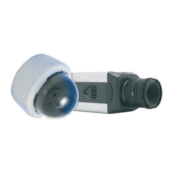
Introduction These instructions cover ICE series fixed dome cameras. Read all of these instructions. Use them to install your camera and have them available for its lifetime. If you have any problems, contact your agent. Models DM/ICED-BH39 Mono high resolution 570 TVL 1/3”... -
Page 4: Important Safeguards
Important Safeguards Product Safety WARNING • Installation and servicing is only to be carried out by suitably qualified and experienced personnel. • Do not remove covers as there is a risk of injury or death by electric shock. • Only power low voltage dome cameras from a class 2 isolated power supply. This camera range is designed for use in general purpose CCTV applications and has no other purpose. -
Page 5: Camera Care
Camera Care In order to avoid damaging your camera, note the following points: CAUTION • Remove all packaging inserts and the protective film from the dome cover before using the camera. • Do not touch the image surface of the sensor. If the sensor is accidentally touched, only clean it using isopropanol. -
Page 6: Installation
Installation The ICE dome camera can be mounted in two ways: ceiling mount for installation into a tile ceiling; surface mount for installation directly to a hard surface or mounting structure. Parts Supplied • 2 x Plastic anchors • 2 x 80 mm (3”) screws Parts Not Supplied •... -
Page 7: Camera Adjustment
Recess Mount Installation Refer to the Quickstart section for more information. To recess mount the camera, the shroud must be removed. Gently squeeze together opposite sides of the shroud as shown and lift it away from the camera body. Using the template supplied at the rear of this manual, mark and cut a 4” (100 mm) diameter hole. -
Page 8: Controls And Switches
Controls and Switches The DIP switches are located on the camera’s circuit board. Dip Switches Note: White indicates default switch position Backlight Compensation The Backlight Compensation (BLC) feature compensates for back-lit scenes by enhancing objects in the centre of the scene which would previously have been in silhouette. Select ON or OFF using the BLC switch. - Page 9 Day/Night (DN Versions only) This switch sets the light level at which the camera automatically switches between day and night operation. Hi sets the camera to switch between day and night mode at higher light level. Lo sets the switching point at a lower light level. The default setting is Lo. When in Night mode, the IR cut filter is removed allowing infra red illumination to be used.
-
Page 10: Final Assy
Final Assy When all the connections and adjustments have been made, re-attach the camera liner and dome cover. DM/ICED-DUM only A self-adhesive blanking label is supplied to cover the opening in the liner. Dedicated Micros ©2007... -
Page 11: Appendix
Appendix Dimensions Dedicated Micros ©2007... -
Page 12: Quickstart
Quickstart Dedicated Micros ©2007... - Page 13 Dedicated Micros ©2007...
- Page 14 Templates ø25mm(1”) 4.5mm( ”) 32.5mm(1 ”) 43mm(1 ”) ø4mm( ”) 43mm(1 ”) NOT TO SCALE Dedicated Micros ©2007...
-
Page 15: Index
Index AGC (Automatic Gain Control) ........................8 Appendix..............................11 Backlight Compensation ..........................8 Camera Adjustment ............................7 Camera Care ..............................5 Camera Position ............................7 Colour Burst..............................9 Contents ................................ 2 Controls and Switches ........................... 8 Day/Night ............................... 9 Declaration of Conformity ..........................4 Dimensions ..............................11 Dip Switches .............................. - Page 16 1200 Daresbury Park, Daresbury, Cheshire, WA4 4HS, UK Dedicated Micros Europe Dedicated Micros USA. Neckarstrafle 15, 23456 Hawthorne Blvd. 41836 Hückelhoven, Germany Suite 100, Torrance, CA 90505, USA Dedicated Micros France Dedicated Micros, Australia PTY. 9-13 rue du Moulinet 5/3 Packard Avenue, Castle Hill, 75013 Paris, France NSW 2154, Australia Dedicated Micros Slovenia Dedicated Micros, Asia PTY Delavska cesta 26, 16 New Industrial Road, 4208 Sencure, Slovenia...
Need help?
Do you have a question about the ICE series and is the answer not in the manual?
Questions and answers