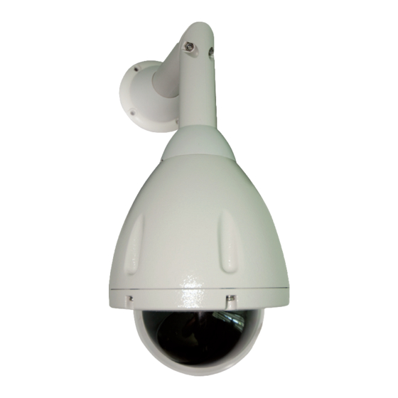
Dedicated Micros 2060 Installation Manual
Dome camera weatherproof and indoor versions
Hide thumbs
Also See for 2060:
- Operation manual (102 pages) ,
- Quick start manual (32 pages) ,
- Menu system manual (207 pages)

Related Manuals for Dedicated Micros 2060


Summary of Contents for Dedicated Micros 2060
- Page 1 2060 Dome Camera Installation Manual Weatherproof and Indoor versions www.dedicatedmicros.com...
-
Page 2: Table Of Contents
Troubleshooting ............ 28 Appendix A ............30 While every attempt is made to ensure these manuals are accurate and current, Dedicated Micros reserve the right to alter or modify the specification of the machine described herein without prejudice. Dedicated Micros ©2009... -
Page 3: Introduction
Introduction The Dedicated Micros 2060 camera is a precision unit, offering a wide variable speed range, together with a large pre-set memory for positions, tours and alarm responses. There are sensitive day/night camera versions with a switchable infra-red filter and with 36 times or 18 times optical zoom lenses plus 12 times digital enhancement suitable for outdoor use, or a colour/mono camera with 18 times optical zoom and 12 times digital enhancement suitable for indoor applications. -
Page 4: Rf Interference Warning
Further details about these applicable standards can be obtained from Dedicated Micros LTD. 1200 Daresbury Park, Daresbury, Cheshire, WA44HS. A “Declaration of Conformity” with all relevant European Union Directives has been made, is on file and is available from the Dedicated Micros address above. -
Page 5: Components Supplied
Operation and Programming Manual Note: The PSU must be 24VAC Power Supply with floating output and a minimum current of 1 amps. Dedicated Micros recommends the DM/94012 for indoor dome for the UK and DM/94013 for Europe. Note: Mounting brackets may have been ordered and delivered separately. - Page 6 Extended corner bracket (order code DM/90008) for mounting to corners of buildings in conjunction with DM/90002. Extended wall bracket (order code DM/90009) for extending out from a wall. All mounting versions are suitable for both weatherproof (IP66 BS EN 60529/NEMA Type 4X) and indoor units. Dedicated Micros ©2009...
-
Page 7: Mounting Configurations - Indoor
Note: Mounting brackets may have been ordered and delivered separately. Wall/Pendant Mount (order code DM/90002) giving pendant or wall mount options. Corner Bracket (order code DM/90007) for mounting to corners of buildings in conjunction with DM/90002. Tile mount (order code DM/CSD/TMR) for suspended ceilings. Dedicated Micros ©2009... -
Page 8: Safety Bond - Weatherproof Dome
Attach safety bond to a suitable secure position in the ceiling void. Note: Always support dome with bond prior to mating connector (B). Weight of dome should be supported by bond ensuring no stress is placed on centre connector (B) at any time. Dedicated Micros ©2009... -
Page 9: Safety Bond - Indoor Dome
Attach bond to a suitable secure position in the ceiling void. Note: Always support dome with bond prior to mating connector. The weight of dome should be supported by bond ensuring no stress is placed on centre connector at any time. Dedicated Micros ©2009... -
Page 10: Ceiling Mounting - Weatherproof Dome
Attach the mounting disc (B) to the ceiling in the chosen position and fix 4x M6x16 socket head cap screws (supplied) into the bushes (C) as shown below. Dedicated Micros ©2009... - Page 11 (C) into the keyhole slots on the base of the dome (F) enclosure. Twist once located to secure, then tighten screw heads (C) to secure the dome enclosure to the mounting disk. Note: Ensure the safety bond is fitted. Dedicated Micros ©2009...
-
Page 12: Wall Mounting Bracket
Note: Locating the dome on the corner of a building will give an increased area of surveillance. For this application, Dedicated Micros offer an optional corner bracket, (DM90007) to adapt the standard wall bracket. Thread the cable from the bracket throught the cable entry hole in the bottom of the bracket casting, then fit the bracket (shown above left). -
Page 13: Tile Mounting - Weatherproof Dome
255mm 113mm Attach the mounting disc (A) to the dome in the chosen position and use 3 of the existing M4 dome hd screws to attach the hemisphere to the dome. Dedicated Micros ©2009... - Page 14 Secure the mounting disc with 4 x supplied off M6 socket button head fixings (D). Fit the supplied safety bond (E) to an attachment point in the ceiling. Note: When using soffit mount, the split clamp ring (F) must be fixed into position using 4 off M4 pan head screws (supplied) Dedicated Micros ©2009...
-
Page 15: Dome Mounting - Weatherproof Dome
Lift the dome to the bracket flange ensuring head of screws pass through the keyhole slots. Twist to locate and lock. Tighten the 4 top mounting fixings with 5mm A/F Hexagonal key (as supplied) to secure. Finally secure the plastic cover to the metal pins on the bracket flange (C). Dedicated Micros ©2009... -
Page 16: Dome Mounting - Indoor Dome
M6x20mm Caphead Screw) pass through the keyhole slots. Twist to locate and lock. Tighten the 4 top mounting fixings with 5mm A/F Hexagonal key (as supplied) to secure. Finally secure the plastic cover to the metal pins on the bracket flange. Dedicated Micros ©2009... -
Page 17: Tile Mounting - Indoor Dome
Snap fit the tile mount bezel (E). This replaces the standard bezel (F) provided with the camera. Discard the standard bezel (F). Note: If the dome requires tile mounting Part E must be ordered separately using part number DM/CSD/TMR. Dedicated Micros ©2009... -
Page 18: Electrical Connections - Weatherproof Dome
Electrical Connections - Weatherproof Dome The Dedicated Micros 2060 external connections are via an IP66 Amphenol connector with 3 metre composite cable flying lead that can be extended to 30 metres max., comprising co-ax, power pair & RS485 pair. This lead should be connected to the boxed P.S.U. supplied with the dome. -
Page 19: Electrical Connections - Indoor
24VAC- from 24VAC 1A 485A Pin 1 on Serial Connection to appropriate DVR 485B Pin 9 on Serial Connector to appropriate DVR Vid GND BNC Earth (screen connection) Vid Sig BNC Signal (centre pin connection) Spare Terminal Not connected Dedicated Micros ©2009... -
Page 20: Control Configuration
The DM 2060 Dome can be controlled by one of three methods. The configuration drawings show the three connection arrangements. DM 2060 domes are delivered with the address switches set at FD (DM/Dennard UTC). DM 2060 with rx domes are delivered with the address switches set at 01. RS485 The switches on each dome must be set to a unique RS485 camera address, refer to ‘Switch... - Page 21 The dome switches must be set according to the UTC protocol, , refer to ‘Switch Configuration - Indoor and Weatherproof Domes’. 1 to 16 Dome Cameras Local Local 230Vac 230Vac Input Input Video cable Video cable To controller Dedicated Micros ©2009...
-
Page 22: Control Switches - Weatherproof Dome
The location of the switches is also shown. This operation should be carried out in an office type environment to avoid ingress of moist air. Note: When reassembling the dome, check the hemisphere sealing gasket is in place and that the hemisphere retaining screws are retightened to avoid water ingress. Dedicated Micros ©2009... -
Page 23: Control Switches - Indoor Dome
Remove and retain the four screws securing the shield to the head and lift off the shield. The location of the switches is also shown. This operation should be carried out in an clean, dry environment. Dedicated Micros ©2009... -
Page 24: Up The Coax Configuration
Scan across the table to identify the values for the blue and yellow switches. For example, if the dome is to be used with a Dedicated Micros PTZ controller system with address ID#5 the switches should be set to ‘05’. i.e. the blue switch should be set to ‘0’ and the yellow switch set to ‘5’. -
Page 25: Extended Rs485 Addressing
Locate SW3 on the main PCB adjacent to the mounted connector attaching the daughter board housing the yellow and blue address switches. Set SW3 using the following parameters Protocol Extended Dennard RS485 on Extended Pelco RS485 Multi-protocol (default) Dedicated Micros ©2009... - Page 26 Termination All Dedicated Micros 2060 domes are fitted with a termination switch, shown above. If a single dome is connected on the RS485 line, or if a star configuration is used, the termination switch should be switched to ‘IN’ (towards the colored address switches).
-
Page 27: Circuit Diagram
WIRE NOT CONNECTED 24Vac FS2 2A FS1 500mA COMPOSITE CABLE FROM DOME POWER TO 240V AC DOME MAINS IN CONNECT FOR RS485 A RS485 CONTROL ONLY RS485 B TO DOME DO NOT CONNECT FOR UP THE CO-AX CONTROL Dedicated Micros ©2009... -
Page 28: Troubleshooting
No joystick dead band recognized as joystick was off centre during powerup. Solution Reboot the controller with the joystick self centred. Reset the Dome (software reset) Open the Technician Menu (see Operation and Programming manual for details on accessing the menu). Select ‘Miscellaneous Services’ Dedicated Micros ©2009... -
Page 29: Software Version
The single letter in the middle of the reference indicates the supported camera, refer to the table below for more information. Letter Camera Model Resolution Format 36x Day/Night 530TVL 36x Day/Night 530TVL NTSC 18x Colour/Mono 460TVL 18x Colour/Mono 470TVL NTSC 18x Day/Night 530TVL 18x Day/Night 530TVL NTSC Dedicated Micros ©2009... -
Page 30: Appendix A
Appendix A DM 2060 Fixed Attitude Dome Camera - Setup Telemetry cameras can be positioned remotely, fixed atitude cameras require manual adjustment to position the camera. Framing the desired camera image will be easier using a local monitor. To Frame the image from a Fixed attitude camera;... -
Page 31: Dm 2060 Fixed Attitude Dome Camera - Electrical Connections
DM 2060 Fixed Attitude Dome Camera - Electrical Connections The Dedicated Micros 2060 Fixed Attitude Camera Dome is supplied with an IP66 Amphenol connector with 3 metre composite cable flying lead. The connector mates with the dome as shown in the image below. -
Page 32: Dm 2060 Fixed Attitude Dome Camera - 'Zoom Cam' Setup
DM 2060 Fixed Attitude Dome Camera - ‘Zoom Cam’ Setup The DM 2060 Fixed Attitude ‘Zoom Cam‘ is equipped wih the ‘zoom cam’ high resolution camera. This offers a range of features which are described below. Control Remote zoom control requires a Dennard, BBV or DM telemetry controller and the removal of lnk ‘B’... - Page 33 Notes Dedicated Micros ©2009...
- Page 34 Notes Dedicated Micros ©2009...
- Page 35 Control Switches - Indoor Dome........................23 Control Switches - Weatherproof Dome ...................... 22 DM 2060 Fixed Attitude Dome Camera - ‘Zoom Cam’ Setup ..............32 DM 2060 Fixed Attitude Dome Camera - Electrical Connections ..............31 DM 2060 Fixed Attitude Dome Camera - Setup ..................30 Dome Mounting - Indoor Dome ........................
- Page 36 Dedicated Micros Benelux 14434 Albemarle Point Place, Suite 100, Joseph Chantraineplantsoen 1, Chantilly, Virginia 20151 USA 3070 Kortenberg, Belgium Dedicated Micros Europe Dedicated Micros, Australia PTY. Hamtorstraße 9, 5/3 Packard Avenue, Castle Hill, 41460 Neuss, Germany NSW 2154, Australia Dedicated Micros France...
Need help?
Do you have a question about the 2060 and is the answer not in the manual?
Questions and answers