
Related Manuals for Dedicated Micros DM18X


Summary of Contents for Dedicated Micros DM18X
-
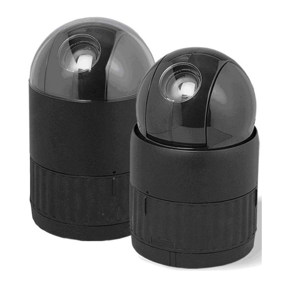
Page 1: Speed Dome Camera
SPEED DOME CAMERA Instruction Manual Model No. : DM/CAM/SD18X/A DM/CAM/SD22X/A DM/CAM/SD26X/A Please read this manual thoroughly before use and keep it handy for future reference. Rev.070514... -
Page 2: Warnings And Cautions
Warnings and Cautions WARNING TO REDUCE THE RISK OF FIRE OR ELECTRIC SHOCK, DO NOT EXPOSE THIS PRODUCT TO RAIN OR MOISTURE. DO NOT INSERT ANY METALLIC OBJECTS THROUGH THE VENTILATION GRILLS OR OTHER OPENINGS ON THE EQUIPMENT. CAUTION EXPLANATION OF GRAPHICAL SYMBOLS The lightning flash with arrowhead symbol, within an equilateral triangle, is intended to alert the user to the presence of uninsulated "dangerous voltage"... -
Page 3: Fcc Compliance Statement
FCC COMPLIANCE STATEMENT FCC INFORMATION: THIS EQUIPMENT HAS BEEN TESTED AND FOUND TO COMPLY WITH THE LIMITS FOR A CLASS A DIGITAL DEVICE, PURSUANT TO PART 15 OF THE FCC RULES. THESE LIMITS ARE DESIGNED TO PROVIDE REASONABLE PROTECTION AGAINST HARMFUL INTERFERENCE WHEN THE EQUIPMENT IS OPERATED IN A COMMERCIAL ENVIRONMENT. -
Page 4: Important Safeguards
IMPORTANT SAFEGUARDS 1. Read these instructions. 2. Keep these instructions. 3. Heed all warnings. 4. Follow all instructions. 5. Do not use this apparatus near water. 6. Clean only with dry cloth. 7. Do not block any ventilation openings. Install in accordance with the manufacturer's instructions. -
Page 5: Table Of Contents
Table of Contents Chapter 1 — Introduction ......................1 1.1 Features...............................1 Chapter 2 — Installation and Configuration ................2 2.1 Package Contents..........................2 2.2 Connector board of Dome Camera......................3 2.3 Setting Dome Camera Termination......................4 2.4 Setting Dome Camera Address (ID) ....................5 2.5 Setting Dome Camera Protocol ......................6 2.6 Connections ............................7 Connecting to the RS-485/ 422 ......................7... - Page 6 3.12 Camera – DM/CAM/SD22X/A MODEL ....................21 Focus Control ............................21 WB (White Balance) Control ........................22 AE Control ............................22 Line Lock Control ..........................23 3.13 Camera - DM/CAM/SD26X/A MODEL ....................23 3.14 Dome Setup............................24 Language Setup ...........................24 Home Function Setup...........................24 OSD Display............................25 View Direction ............................25 Dome OSD Display ..........................25 Area Display ............................25 View Angle Setup ..........................26...
-
Page 7: Chapter 1 - Introduction
Chapter 1 — Introduction 1.1 Features • 240 Preset positions.(1-32,35-59:by PELCO-P protocol) • 8 Tours consist of Preset, Pattern, Auto-Scan and other Tours can be programmed with over 300 functions and Preset location. While moving, each Preset scan can be watched in smooth Vector Scan mode. -
Page 8: Chapter 2 - Installation And Configuration
Chapter 2 — Installation and Configuration 2.1 Package Contents The package contains the following. Dome Camera ………………………1 Bubble Ring ………………………1 Instruction Manual (This Document) ………………………1 Assembly Screws for Attaching a dome ………………………3 Plastic Anchor ………………………3 10Pin Connector ………………………1 12Pin Connector ………………………2 CAUTION: Be sure to have caution labels ( version only) on both the body and the base... -
Page 9: Connector Board Of Dome Camera
2.2 Connector board of Dome Camera Figure 2 – CONNECTOR BOARD... -
Page 10: Setting Dome Camera Termination
The dome camera must be installed by qualified service personnel in accordance with all local and federal electrical and building codes. The system should be installed according to Figures 2 through 6. Termination Switches KSD02H Address(ID) and Protocol selection Switches Figure 3 –... -
Page 11: Setting Dome Camera Address (Id)
2.4 Setting Dome Camera Address (ID) To prevent damage, each dome camera must have a unique address (ID). When installing multiple dome cameras using a multiplexer, it is suggested that the dome camera address match the multiplexer port number. If you want to set the address more than 999, you should contact the service provider. Example: Port 1 = Dome 1, Port 2 = Dome 2 …... -
Page 12: Setting Dome Camera Protocol
2.5 Setting Dome Camera Protocol If a dome camera is to be installed with a Dedicated Micros KBS3 keyboard, select the switch as the same as the Dedicated Micros DVR. Consult service personnel if a dome camera is installed with device other than a keyboard controller. -
Page 13: Connections
2.6 Connections • Connecting to the RS485/ 422 The dome camera can be controlled remotely by an external device or control system, such as a control keyboard, using RS485 half-duplex, RS422 duplex or simplex serial communications signals. Connect Marked Rx+(Tx+), Rx-(Tx-) to Tx+ and Tx- of the RS485 control system. If control system is RS422, connect Rx+(Tx+), Rx-(Tx-) and Rx+, Rx- of the dome camera to Rx+, Rx- and Tx+, Tx- of the control device respectively. -
Page 14: Getting Started
Chapter 3 — Program and Operation 3.1 Dome Camera Selection The Dedicated Micros KBS3 keyboard is the recommended device for controlling the PTZ camera. Before you program or operate a dome camera, you must select the dome camera by pressing the camera number key. -
Page 15: Accessing On-Screen Menu Utility
3.2 Accessing the On-Screen Menu Utility You can call up the On-screen menu utility on your monitor by pressing PRESET . The DVR displays the following pop-up window: Goto preset Enter PRESET number Pressing 95 will display the following On-screen menu. DOME MENU AUTO SCAN PRESET... - Page 16 SPEED(MODE) : NORMAL1~NOMAL9,SLOW VECTOR,FAST VECTOR NORMAL1 (SLOWER) ↔ NORMAL9 ( FASTER) SLOW VECTOR, FAST VECTOR : Move from start point to end point including tilt and zoom simultaneously and linearly. In case of 22x model, zoom is fixed at more wide angle and the zoom magnification information is not displayed.
-
Page 17: Preset
3.4 Preset If you need to view specific places routinely, you should program presets. A preset is a programmed video scene with automatic pan, tilt, zoom, focus and iris settings. Once programmed, pressing a PRESET button and entering the number on your keyboard automatically calls up the preset. -
Page 18: Shortcut Of Preset Program
5. After aiming the camera (view direction and lens control), press PRESET + 95 again. 6. Then twist the Joystick handle or press ZOOM IN or ZOOM OUT Key to store the selected view. The position number will be displayed and the user will be prompted to enter a preset title. -
Page 19: Tour
3.6 Tour There are 8 programmable Tours. Each Tour consists of up to 42 Preset positions, Patterns, Scans or other Tours (second-level). Using second-level Tours, it can be expanded to over 300 functions in a single Tour. However second level Tours will be ignored when called by a Tours. The following example illustrates this concept: Tour1 has Preset1 Preset2... -
Page 20: Pattern
4. To add a stored preset as a Tour, twist the Zoom handle or press Zoom Key (Programmed preset will scroll). To remove a stored preset from the Tour, press PRESET + 91 keys, blank position mark (===) will be displayed. You can overwrite the programmed position. 5. -
Page 21: Alarm
1. Press PRESET + 95 keys to display the main menu on the monitor. 2. Scroll down to PATTERN and push the Joystick to the right. Or simply press the PRESET + 80 key rather than use the Main Menu. 3. -
Page 22: Area Title
1. Press Menu to display the main menu on the monitor. Select the Alarm option by pushing the Joystick up or down and push to right to enter the detail menu. 2. Select the alarm input number by pushing the Joystick up or down and select the column you wish to setup. -
Page 23: Privacy Zone
4. To adjust panning limit, press the PRESET + 95 keys on the start or end field. Then use the Joystick to go the desired direction. Press the PRESET + 95 keys to finish. The end limit must be in an increasing direction. (Start < End). 5. -
Page 24: Camera - Dm/Cam/Sd18X/A , Sd26X/A Model
3.11 Camera – DM/CAM/SD18X/A, SD26X/A MODEL NOTE: The menu features will vary depending on the camera module installed in your dome camera. CAMERA SETUP FOCUS CONTROL WB CONTROL AE CONTROL LINE LOCK CONTROL SHARPNESS BACK LIGHT : OFF DIGITAL ZOOM : OFF (2X/4X/MAX) NIGHT SHOT CONTROL SAVE AND EXIT(ESC TO CANCEL) -
Page 25: Wb (White Balance) Control
• WB (White Balance) CONTROL WB SETUP MODE AUTO R GAIN : B GAIN : EXIT(ESC TO EXIT) MODE MANUAL / AUTO / INDOOR / OUTDOOR / ONE PUSH / ATW RGAIN 0 ~ 255 BGAIN 0 ~ 255 Use the ATW mode for normal use. RGAIN / BGAIN modes are controllable only in MANUAL Mode Push the Joystick to the right or left to change. -
Page 26: Line Lock Control
• LINE LOCK CONTROL LINE LOCK SETUP MODE INTERNAL PHASE EXIT(ESC TO EXIT) MODE INTERNAL / EXTERNAL Adjusts phase of picture with other PHASE 0~255 cameras in EXTERNAL mode. EXIT (ESC TO EXIT) • NIGHT SHOT MENU The NIGHT SHOT option removes the IR cutoff filter of the camera and makes the camera sensitive to near infrared. -
Page 27: Camera - Dm/Cam/Sd22X/A Model
3.12 Camera – DM/CAM/SD22X/A MODEL CAMERA SETUP FOCUS CONTROL WB CONTROL AE CONTROL LINE LOCK CONTROL SHARPNESS : 10 BACK LIGHT : OFF DIGITAL ZOOM : OFF (MAX) SAVE AND EXIT(ESC TO CANCEL) The higher the value, the more edges in the picture will be enhanced SHARPNESS User can adjust sharpness level from 0 to 20. -
Page 28: Wb (White Balance) Control
• WB (White Balance) CONTROL WB SETUP MODE R GAIN : B GAIN : EXIT(ESC TO EXIT) MODE AWB / WAWB / INDOOR / DOUDOOR / MANUAL WAWB Wide range auto white balance mode. RGAIN 0 ~ 255 BGAIN 0 ~ 255 Use the AWB mode for normal use. -
Page 29: Line Lock Control
• LINE LOCK CONTROL LINE LOCK SETUP MODE INTERNAL PHASE : EXIT(ESC TO EXIT) MODE INTERNAL / EXTERNAL Adjusts phase of picture with other PHASE 0~255 cameras in EXTERNAL mode. EXIT (ESC TO EXIT) 3.13 Camera – DM/CAM/SD26X/A MODEL Eclipse of the Lens: The eclipse phenomenon occurs with this model. -
Page 30: Dome Setup
3.14 Dome Setup CONFIGURATION MENU LANGUAGE SETUP HOME FUNCTION SETUP OSD DISPLAY VIEW ANGLE SETUP INITIALIZE DATA ORIGIN OFFSET DOME RESET P-RESPONSE : OFF SYSTEM INFORMATION EXIT(ESC TO EXIT) P-RESPONSE The option should be set to OFF when the camera is connected to a DVR. This disables the response command from the dome in the PELCO-P protocol. -
Page 31: Osd Display
The Home function can be set so that the camera automatically goes to Preset, Tour, Pattern, Auto Scan after the keyboard controller has been idle for a amount of time. For example, if the Joystick controller is idle for 10 seconds, the camera goes to preset 1. Follow these steps to program the Home position: 1. -
Page 32: View Angle Setup
to the right or to the left. The Dome camera’s OSD will override this function (Dome camera’s OSD must be enabled). • VIEW ANGLE SETUP VIEW ANGLE SETUP PANNING RANGE FLIP : ON TILT OVER ANGLE : W/O BUBBLE SAVE AND EXIT(ESC TO CANCEL) •... -
Page 33: Initialize Data
• INITIALIZE DATA INITIALIZE DATA FACTORY DEFAULT ERASE PROGRAMMED DATA EXIT(ESC TO EXIT) Erase all stored data from the Flash-ROM of the selected dome camera. You will be asked to enter Yes or No. If you intend to erase all data then press the PRESET + 95 key, otherwise press the PRESET + 96 key to exit without erasing. -
Page 34: Appendix A - Specifications
Appendix A — Specifications Camera (DM/CAM/SD18X/A) Image Sensor 1/4" Ex-view HAD Color CCD (Sony) NTSC : 768 x 494 Approx. 380K pixels Picture elements : 752 x 582 Approx. 440K pixels Horizontal Resolution 480 / 470 lines (NTSC / PAL) 18x optical zoom with auto focus Lens 12x digital zoom... - Page 35 General Certification CE EMC, FCC CLASS A, CSA Electrical Input Voltage 18 to 30VAC; 24VAC nominal, 24VDC Power Requirement 24VAC/VDC 1A Power Consumption Maximum 20W Alarm Output 4 Normal relays 24VDC/1A Max. (selectable NC/NO) Alarm Input 8 Normal dry contact (selectable NC/NO) Control RS-485/422 baud rate: 2400~230k bps (default: 9600bps) Access Time...
-
Page 36: Appendix B - Troubleshooting
Appendix B — Troubleshooting If problems occur, verify the installation of the camera with the instructions in this manual and with other operating equipment. Isolate the problem to the specific piece of equipment in the system and refer to the equipment manual for further information. Problem Possible Solution Verify that power is connected to all pieces of... -
Page 37: Appendix C - Glossary
Appendix C — Glossary Alarm Actions The assigned responses for the dome camera when inputs change from normal to abnormal states. The dome may run a Preset, Pattern, or have no assigned action for each of the four dome inputs. The dome may also send alarm states to the host controller for processing. See also Input and Normal Input State. -
Page 38: Line Lock
IR Mode A feature of the camera that permits manual or automatic switching between color and IR (black-and-white) operation. When IR mode is active, clearer images may be obtained under low-light conditions. Line Lock Allows you to phase lock the video with the AC power line. When line lock is enabled, it prevents vertical video rolling when switching multiple cameras to a single monitor. -
Page 39: Appendix D - Bubble Ring
Privacy Zones Masked areas of the dome camera's viewing area. These masks prevent operators of the surveillance system from viewing these designated zones. The Privacy Zones move in relation to the dome camera’s pan/tilt position. In addition, the apparent size of the Privacy Zone adjusts automatically as the lens zooms in or out. -
Page 40: Appendix E - Short Cut Key (Pelco Protocol) By Kbs3 Keyboard
MENU key PRESET + 95 CTRL key in the menu PRESET + 95 Release CTRL key in the menu PRESET + 95 ESC key PRESET + 96 Run AutoPan (endless panning)(or AUTOPAN button) PRESET + 99 Dedicated Micros Model KBS3A Keyboard...
Need help?
Do you have a question about the DM18X and is the answer not in the manual?
Questions and answers