Sign In
Upload
Manuals
Brands
SEW-Eurodrive Manuals
Controller
MOVIFIT FC
SEW-Eurodrive MOVIFIT FC Manuals
Manuals and User Guides for SEW-Eurodrive MOVIFIT FC. We have
5
SEW-Eurodrive MOVIFIT FC manuals available for free PDF download: Operating Instructions Manual, Manual
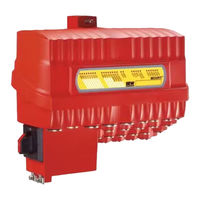
Sew Eurodrive MOVIFIT FC Manual (178 pages)
Functional Safety with S12 Safety Option
Brand:
Sew Eurodrive
| Category:
Security Sensors
| Size: 13 MB
Table of Contents
Table of Contents
3
1 General Information
9
How to Use this Documentation
9
Structure of the Safety Notes
9
Meaning of Signal Words
9
Design of the Section-Related Safety Notes
9
Design of the Embedded Safety Notes
9
Rights to Claim under Warranty
10
Content of the Documentation
10
Exclusion of Liability
10
Other Applicable Documentation
10
Product Names and Trademarks
10
Copyright
10
2 Safety Notes
11
General Information
11
Target Group
11
Designated Use
12
Transportation and Storage
12
Installation
13
Definitions
13
3 Safety Concept
14
Safety Concept for MOVIFIT ® FC Frequency Inverters
14
Description of the Function
14
MOVIFIT ® FC Block Diagram
14
Restrictions
15
Safety Concept of S12 Safety Option
16
Drive Safety Functions
17
STO - Safe Torque off
17
Ss1(A) - Safe Stop 1
18
Ss1(C) - Safe Stop 1
19
SLS - Safely Limited Speed
20
SDI - Safe Direction
21
Safety Concept of Assist S12
22
Safety Parameters
22
Test Concept and Test Procedure
22
4 Safety Conditions
24
Notes on Stop Categories
24
Nameplates
25
Nameplate Position
25
Nameplate of Complete Unit
25
Description of FS Logo
26
Installation Requirements
26
Sensor and Actuator Requirements
27
Startup Requirements
27
Operational Requirements
27
5 Hazard Caused by a Coasting Drive
28
6 Electrical Installation
29
Installation Instructions
29
UL-Compliant Installation
29
Safe Disconnection of MOVIFIT
30
Movifit ® Fc
30
Connection Example, Power Bus
32
Safety-Related Stopping with S12 Safety Option
33
S12 Safety Option - Electrical Installation
34
Terminal Assignment
34
Safety-Related Inputs (F-DI.)
37
Safety-Related Outputs (F-DO. and F-DO_STO)
45
Incremental Encoder EI7C FS
51
Properties
51
Installation
51
7 Safety Functions of the S12 Safety Option
57
STO - Safe Torque off
57
Description of the Function
57
Activation
58
Status
58
Parameter
58
Ss1(C) - Safe Stop 1
59
Description of the Function
59
Activation
59
Status
59
Parameter
59
Ss1(A) - Safe Stop 1
60
Description of the Function
60
Activation
61
Status
61
Parameter
61
SLS - Safely Limited Speed
62
Description of the Function
62
Activation
63
Status
63
Error Response
63
Parameter
64
Speed Filter Determination
64
SDI - Safe Direction
66
Description of the Function
66
Activation
67
Status
67
Error Response
67
Parameter
67
Safety-Related Inputs
68
Description of the Function
68
Connection Type
68
Parameter
70
Safety-Related Outputs
71
Description of the Function
71
Parameter
71
Function Assignment
72
Parameter
72
Test Mode
73
Description of the Function
73
Activation
73
Status
73
7.10 Coasting Time Measurement
74
7.10.1 Definition
74
7.10.2 Description of the Function
74
7.10.3 Activation
75
7.10.4 Parameter
75
8 Startup
76
General Startup Instructions
76
Startup Variants
76
Startup with Default Parameter Setting
76
Startup for Independent Operation
77
Startup with Profisafe Connection
77
Setting the Safety Function Parameters
78
Requirements
78
Procedure
78
Startup of the Fieldbus and the Higher-Level F-PLC
80
Requirements
80
Setting the Profisafe Address
80
Configuring the S12 Safety Option in STEP 7
82
Verification and Validation
86
Overview
86
Verification
86
Validation
88
9 Assist S12
89
Structure of the User Interface
89
Menu Bar
90
Parameterization Steps
90
Tool Bar
91
Parameterization Window
91
Plausibility Error Indication
92
Status Bar
92
Change Password
93
Data Management
94
Data Management with Non-Configured S12 Safety Option
95
Data Management with Configured S12 Safety Option
96
Parameterization
97
Changing the Parameter Settings
101
Parameter Display
102
Safety Functions
103
Safety Function Status
104
DO Outputs
106
Process Data
107
Error Memory
108
10 Data Exchange
109
Periphery Access of the S12 Safety Option in STEP 7
110
User Data of S12 Safety Option
112
Activation Examples for the S12 Safety Option
116
11 Response Times
120
12 Service
121
FDI.." and "FDO.." Leds
122
State" Led
123
Profisafe Timeout
124
Safety Diagnostics Via PROFINET IO
125
Error Memory
128
Unit Replacement
129
Replacing the EBOX
130
Replacing the ABOX With/Without EBOX
131
Error Table of the S12 Safety Option
132
13 Parameter Description
137
Minimum Motor Speed (N2)
138
Do
139
Sto / Sbc
141
Ss1C Delay (T1)
142
Function
143
SLS (General)
144
SDI Tolerance
145
Safety-Related Outputs
146
14 Application Examples
147
Example 2: Profisafe Connection
149
15 Technical Data
151
Technical Data: S12 Safety Option
153
Safety-Related Outputs
154
Encoder Interface
155
FC (Safety Technology)
156
16 Address List
169
Index
169
Advertisement
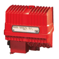
SEW-Eurodrive MOVIFIT FC Operating Instructions Manual (228 pages)
Decentralized Drive Control
Brand:
SEW-Eurodrive
| Category:
Controller
| Size: 19 MB
Table of Contents
Table of Contents
3
1 General Information
6
How to Use this Documentation
6
Structure of the Warning Instructions
6
Rights to Claim under Limited Warranty
8
Exclusion of Liability
8
Other Applicable Documentation
8
Product Names and Trademarks
8
Copyright Notice
8
2 Safety Notes
9
Preliminary Information
9
General Information
9
Target Group
9
Designated Use
10
Transportation, Storage
10
Installation
11
Electrical Connection
11
Safe Disconnection
11
Operation
12
3 Unit Structure
13
Movifit ® Fc
13
Overview - Connection Configuration
14
EBOX (Active Electronics Unit)
16
ABOX (Passive Connection Unit)
17
Hygienic Plus Design (Optional)
18
MOVIFIT ® with L10 PROFINET Interface SCRJ/POF
20
MOVIFIT FC Type Designation
21
4 Mechanical Installation
28
General Information
28
Tools Required
28
Permitted Mounting Position
29
Installation
30
Central Opening/Closing Mechanism
36
Tightening Torques
39
MOVIFIT ® Hygienic Plus Design
41
5 Electrical Installation
44
General Information
44
Installation Planning Taking EMC Aspects into Account
44
Installation Instructions (All Versions)
46
Additional Installation Instructions for Group Drives
57
Installation Topology (Example)
58
Standard ABOX MTA
59
Hybrid ABOX MTA
79
Hybrid ABOX MTA
82
Hybrid ABOX MTA
85
Hybrid ABOX MTA
89
Hybrid ABOX MTA
92
Hybrid ABOX MTA
95
Electrical Connections
98
Encoder Connection
112
Power Bus Connection Examples
114
Fieldbus Systems Connection Examples
115
Hybrid Cable
119
Wiring Notes
125
Wiring Check
126
6 Startup
127
General Information
127
Requirements
128
Description of the DIP Switches
128
Startup Procedure
138
Startup of MOVIFIT ® on the Fieldbus
139
Starting up MOVIFIT
143
Frequency Inverter
143
7 Operation
146
Status Leds for MOVIFIT
146
Manual Operation Using the DBG Keypad
168
8 Service
169
Unit Diagnostics
169
Error List
169
Inspection/Maintenance
172
SEW-EURODRIVE Service
172
Shutdown
173
Storage
173
Extended Storage
173
Disposal
174
9 Technical Data
175
Conformity
175
Design with Operating Point 400 V/50 Hz
176
Design with Operating Point 460 V/60 Hz
178
Electronics Data
180
Binary Inputs
181
Binary Outputs DO00 - DO03
181
Binary Output DB00
182
Interfaces
182
Cable Type "A" Hybrid Cable
187
Operation for Motors with Mechanical Brake
189
Internal Braking Resistors
190
External Braking Resistors
191
Hygienic Plus Design
192
Accessories
194
Dimension Drawings
195
10 Declaration of Conformity
203
11 Address List
206
Index
216
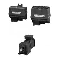
Sew Eurodrive MOVIFIT FC Operating Instructions Manual (200 pages)
Decentralized Drive Systems
Brand:
Sew Eurodrive
| Category:
Controller
| Size: 23 MB
Table of Contents
Table of Contents
3
1 General Information
6
How to Use this Documentation
6
Structure of the Safety Notes
6
Rights to Claim under Warranty
7
Exclusion of Liability
7
Copyright
7
Product Names and Brands
7
2 Safety Notes
8
Preliminary Information
8
General Information
8
Target Group
8
Designated Use
9
Other Applicable Documentation
9
Transportation and Storage
10
Installation
10
Electrical Connection
10
Safe Disconnection
10
2.10 Operation
11
3 Unit Structure
12
Movifit ® Fc
12
Overview of Connection Configurations
13
EBOX (Active Electronics Unit)
15
ABOX (Passive Connection Unit)
16
Hygienic Plus Variant (Optional)
17
MOVIFIT ® with L10 PROFINET Interface SCRJ/POF
19
Type Designation MOVIFIT ® FC
20
4 Mechanical Installation
24
General Information
24
Permitted Mounting Position
25
Installation
26
Central Opening/Closing Mechanism
32
Tightening Torques
35
MOVIFIT ® Hygienic Plus Variant
37
5 Electrical Installation
40
General Information
40
Installation Planning Taking EMC Aspects into Account
40
Installation Instructions (All Variants)
42
Additional Installation Instructions for Group Drives
49
Installation Topology (Example)
50
Standard ABOX MTA
51
Hybrid ABOX MTA
69
Hybrid ABOX MTA
72
Hybrid ABOX MTA
75
Hybrid ABOX MTA
79
Hybrid ABOX MTA
82
Hybrid ABOX MTA
85
5.13 Electrical Connections
88
5.14 Encoder Connection
98
Power Bus Connection Examples
101
5.16 Fieldbus Systems Connection Examples
102
5.17 Hybrid Cables
105
5.18 Wiring Notes
110
5.19 Wiring Check
111
6 Startup
112
General Information
112
Requirements
113
Description of the DIP Switches
113
Startup Procedure
121
Startup of MOVIFIT ® on the Fieldbus
122
Starting up the MOVIFIT ® Frequency Inverter
126
7 Operation
129
MOVIFIT ® FC Status Leds
129
Manual Operation Using the DBG Keypad
144
8 Service
145
Unit Diagnostics
145
Error Table
145
Inspection/Maintenance
148
SEW Electronics Service
149
Shutdown
149
Storage
150
Extended Storage
150
Disposal
150
9 Technical Data
151
CE Marking, UL Approval and C-Tick
151
Variant with Operating Point 400 V / 50 Hz
152
Variant with Operating Point 460 V / 60 Hz
153
Electronics Data
154
Binary Inputs
154
Binary Outputs DO00 - DO03
155
Binary Output DB00
155
Interfaces
155
Hybrid Cables - Cable Type "A
159
9.10 Braking Torques
161
Operation for Motors with Mechanical Brake
162
Internal Braking Resistors
163
9.13 External Braking Resistors
164
Hygienicplus Variant
165
Options and Accessories
167
Dimension Drawings
168
10 Declaration of Conformity
176
11 Address List
178
Index
190
Advertisement
SEW-Eurodrive MOVIFIT FC Manual (80 pages)
Functional Safety
Brand:
SEW-Eurodrive
| Category:
Safety Equipment
| Size: 7 MB
Table of Contents
Table of Contents
3
1 General Information
4
Structure of the Safety Notes
4
Right to Claim under Warranty
4
Exclusion of Liability
5
Other Applicable Documentation
5
2 Safety Concept
6
MOVIFIT ® MC Safety Concept
6
Safety Concept for MOVIFIT ® FC Frequency Inverters
8
Safety Concept for Profisafe Option S11
10
Safety Functions
11
3 Safety Conditions
13
Notes on Stop Categories
13
Approved Devices
14
Installation Requirements
19
External Safety Controller - Requirements
20
External Sensors and Actuators - Requirements
21
Startup Requirements
21
Operation Requirements
21
4 Hazard Caused by Drive Coasting
22
5 Electrical Installation
23
Installation Instructions
23
Safe Disconnection MOVIFIT ® MC and FC
26
Profisafe Option S11
29
6 Startup with Profisafe Option S11
38
Setting the Profisafe Address
38
Configuring the Profisafe Option in STEP7
39
7 Data Exchange with Profisafe Option S11
43
Introduction
43
Access to F Periphery of the Profisafe Option S11 in Step 7
44
8 Profisafe Option S11 - Response Times
51
9 Diagnostics with Profisafe Option S11
52
Diagnostics Leds
52
Error Statuses of Profisafe Option S11
54
10 Technical Data
59
Technical Data - MOVIFIT ® MC (Safety Technology)
59
MOVIFIT ® MC Characteristic Safety Values
59
Technical Data - MOVIFIT ® FC (Safety Technology)
60
MOVIFIT ® FC Characteristic Safety Values
60
Technical Data - Profisafe Option S11
61
10.6 Profisafe Option S11 Characteristic Safety Values
62
11 Address List
63
Index
74
SEW-Eurodrive MOVIFIT FC Manual (38 pages)
Function Level "Technology" with Interface for PROFINET IO, PROFIBUS or Ethernet/IP Application Solution "Bus Positioning"
Brand:
SEW-Eurodrive
| Category:
Controller
| Size: 4 MB
Table of Contents
Table of Contents
3
1 General Information
5
How to Use this Documentation
5
Structure of the Safety Notes
5
Meaning of Signal Words
5
Structure of the Section-Related Safety Notes
5
Structure of the Embedded Safety Notes
5
Right to Claim under Warranty
6
Exclusion of Liability
6
Copyright
6
Product Names and Brands
6
Other Applicable Documentation
7
2 Safety Notes
8
General Information
8
Target Group
9
Designated Use
10
Bus Systems
10
3 System Description
11
Area of Application
11
Profiles
11
4 Operating Modes
12
Jog
12
Jog Mode Flow Diagram
12
Referencing
13
Referencing Mode Flow Diagram
13
Positioning
14
Positioning Mode Flow Diagram
14
5 Project Planning Information
15
6 Startup
16
Requirements
16
Setting the "Bus Positioning for MOVIFIT ® " Application Module
16
General Settings
16
Scaling
18
Monitoring
19
Reference Travel
22
7 Download
24
8 Operation and Diagnostics
25
Monitor Mode and Control Mode
25
Monitor Mode
25
Control Mode
26
9 Process Data and Terminal Assignment
27
Input Terminal Assignment
27
Process Data Assignment
27
Overview
27
PD (Single-Motor Operation)
28
PD (Dual-Motor Operation)
30
Index
34
Advertisement
Related Products
SEW Eurodrive MOVIFIT compact
Sew Eurodrive MOVIFIT MC
SEW-Eurodrive MOVIFIT-MC
SEW-Eurodrive MOVIFIT-SC
SEW-Eurodrive MOVITRAC 07
SEW Eurodrive MOVI-PLC
Sew Eurodrive MOVI-PLC advanced
Sew Eurodrive MOVI-C Series
Sew Eurodrive MOVIPRO PHE Series
SEW-Eurodrive MOVI-C FIELD CONTROLLER standard
SEW-Eurodrive Categories
Industrial Equipment
DC Drives
Controller
Inverter
Engine
More SEW-Eurodrive Manuals
Login
Sign In
OR
Sign in with Facebook
Sign in with Google
Upload manual
Upload from disk
Upload from URL