
Subscribe to Our Youtube Channel
Related Manuals for SEW-Eurodrive MOVIFIT basic


Summary of Contents for SEW-Eurodrive MOVIFIT basic
- Page 1 Drive Technology \ Drive Automation \ System Integration \ Services Operating Instructions ® MOVIFIT basic Edition 05/2013 20116543 / EN...
- Page 2 SEW-EURODRIVE—Driving the world...
-
Page 3: Table Of Contents
Contents Contents General information .................... 5 How to use this documentation..............5 Structure of the safety notes ............... 5 Rights to claim under warranty ..............6 Exclusion of liability..................6 Copyright..................... 6 Product names and trademarks ..............6 Safety notes......................7 Preliminary information ................ - Page 4 Contents Parameterization with LT-BG keypad ............42 Parameterization with the PC ..............45 ® Parameter directory of the MOVIFIT basic inverter ........ 49 ® Functions of MOVIFIT basic with AS-Interface ........53 ® 6.10 Functions of MOVIFIT basic with binary control ........54 Operation ......................
-
Page 5: General Information
If you are unclear about any of the information in this documentation, or if you require further information, contact SEW-EURODRIVE. Structure of the safety notes 1.2.1... -
Page 6: Rights To Claim Under Warranty
You must comply with the information contained in this documentation to ensure safe operation and to achieve the specified product characteristics and performance fea- tures. SEW-EURODRIVE assumes no liability for injury to persons or damage to equip- ment or property resulting from non-observance of these operating instructions. In such cases, any liability for defects is excluded. -
Page 7: Safety Notes
Safety notes Preliminary information Safety notes The following basic safety notes must be read carefully to prevent injury to persons and damage to property. The operator must ensure that the basic safety notes are read and adhered to. Make sure that persons responsible for the plant and its operation, as well as persons who work independently on the unit, have read through the operating instruc- tions carefully and understood them. -
Page 8: Designated Use
Safety notes Designated use Designated use ® MOVIFIT basic drives are components intended for installation in electrical systems or machines. ® In case of installation in machines, startup of MOVIFIT basic units (i.e. start of desig- nated operation) is prohibited until it is determined that the machine meets the require- ments stipulated in the Machinery Directive 2006/42/EC. -
Page 9: Electrical Connection
Safety notes Electrical connection Electrical connection Perform electrical installation according to the pertinent regulations (e.g. cable cross sections, fusing, protective conductor connection). For any additional information, refer to the applicable documentation. For notes on EMC compliant installation, such as shielding, grounding, arrangement of filters and routing of lines, refer to chapter "Installation instructions". -
Page 10: Unit Structure
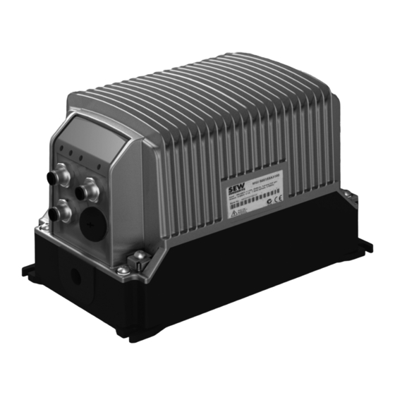
Unit structure ® MOVIFIT basic Unit structure ® MOVIFIT basic ® MOVIFIT basic is a decentralized drive unit for controlling AC motors. 2816397195 Control unit EBOX with cooling fins and electronics (inverter or motor starter) X8 connection for motor (only with dual motor starter design) X9 connection for motor Nameplate PE connection... -
Page 11: Accessories
Unit structure Accessories Accessories ® You can order the following accessories for MOVIFIT basic from SEW-EURODRIVE: Accessories Part number (SEW-EURODRIVE) Motor connection cable 4 x 2.5 mm , unshielded, length = 3 m 1 814 874 3 with plug connector Q8/0 – open conductor ends Motor connection cable 7 x 2.5 mm... -
Page 12: Type Designations
Unit structure Type designations Type designations 3.4.1 Nameplate ® The following figure gives an example of a nameplate of the MOVIFIT basic inverter: 3782535691 3.4.2 Type designation ® The following table shows the MOVIFIT basic type designation: MBF07A-K1-A1 Connection module Version Control K = via AS-Interface... -
Page 13: Mechanical Installation
Mechanical installation Installation instructions Mechanical installation Installation instructions 4.1.1 General information NOTICE ® Loss of warranted degree of protection if the MOVIFIT basic inverter is installed incorrectly or not at all. ® Damage to the MOVIFIT basic unit. • If you remove the EBOX from the ABOX, you have to protect the EBOX and the ABOX from moisture and dust. -
Page 14: Mounting Position
Mechanical installation Mounting position Mounting position ® You can install the MOVIFIT basic unit in any mounting position. 2816420235 ® Installing MOVIFIT basic ® Mount the MOVIFIT basic unit with 4 screws according to the following figure: (Tightening torque 2.0 – 2.4 Nm (18 – 21 lb.in)) 9007202071159307 Operating Instructions –... -
Page 15: Electrical Installation
RCDs are permitted as a protective device. During normal operation of MOVIFIT basic units, leakage currents > 3.5 mA can occur. • SEW-EURODRIVE recommends that you do not use RCDs. However, if a residual current device is stipulated for direct or indirect protection against contact, observe the above note. - Page 16 Electrical installation Installation instructions 5.1.3 Notes on PE connection WARNING Electric shock due to incorrect connection of PE. Severe or fatal injuries. • Observe the following notes regarding PE connection. PE connection in Establish a PE connection in the unit. the unit 3160365451 ®...
- Page 17 For detailed information on EMC compliant installation, refer to the publication "Electromagnetic Compatibility in Drive Engineering" from SEW-EURODRIVE. With respect to the EMC regulation, frequency inverters cannot be operated as stand- alone units. Regarding EMC, they can only be evaluated when they are integrated in a drive system.
-
Page 18: Topology
Electrical installation Topology Topology ® The following figure shows a typical MOVIFIT basic drive system with AS-Interface control: AC 3 x 380 - 480 V 9007201945761931 K: Line contactor Circuit breaker for Power bus (line cable) Motor cable line protection Type Minimum con- Maximum... -
Page 19: Power Bus Connection (Line Cable)
Electrical installation Power bus connection (line cable) Power bus connection (line cable) WARNING Electric shock due to charged capacitors. Severe or fatal injuries. ® • De-energize the MOVIFIT basic drive using a suitable external cut-off device be- fore removing the EBOX from the ABOX. •... - Page 20 Electrical installation Power bus connection (line cable) ® 3. Pull both locking tabs to the outside and tilt up the upper part of the FieldPower con- tact module. 2839866123 4. Loosen the 4 screws and remove the strain relief brackets. Remove the two cable seals.
- Page 21 Electrical installation Power bus connection (line cable) 6. Fix the cable seals around the line cable. NOTICE Ingression of moisture or dust due to incorrect cable seal. ® Damage to the MOVIFIT basic unit. • Only use cable seals approved for the line cable diameter. Insert the cable seals with the line cable in the recesses in the ABOX.
- Page 22 Electrical installation Power bus connection (line cable) 8. Screw the strain relief brackets to the ABOX and fix the line cable with the brackets (tightening torque: 0.6 Nm, 5.3 lb.in). 2839875723 9. Place the upper part of the contact module on the hinge hooks. Tilt down the upper part of the contact module until it latches on both sides.
- Page 23 Electrical installation Power bus connection (line cable) ® 11.Plug in the line connector of the EBOX to the FieldPower contact module. 2839881483 12.Position the EBOX on the ABOX. Screw on the EBOX with 4 screws (tightening torque: 2 Nm, 18 lb.in). 2839860363 NOTICE Ingression of moisture or dust when bending the line cable.
-
Page 24: Motor Connection
Electrical installation Motor connection Motor connection 5.4.1 Motor connection variants ® The following figure shows the motor plug connector variants for MOVIFIT basic: ® ® MOVIFIT basic inverter MOVIFIT basic dual motor starter ® MOVIFIT basic reversing starter 2816406795 2816404875 X9 Motor connection X8 Motor connection Operating Instructions –... - Page 25 Electrical installation Motor connection 5.4.2 X9, (X8): Motor connection ® The X8 plug connector is only available in conjunction with MOVIFIT basic with dual- motor starter Connection The following table provides information about this connection: Function Power connection for motor with brake Connection type Q 8/0, female Wiring diagram...
- Page 26 Electrical installation Motor connection Connection cable The following table shows possible motor cables: NOTICE Danger in case of incorrect wiring of U1, V1, and W1 or short circuit. The motor outputs ® of MOVIFIT basic are not protected against short circuits. ®...
- Page 27 Electrical installation Motor connection Connection cable and component Length/ ® MOVIFIT Motor cable Installa- Motor connection basic tion type Motor without brake Cable design: 4G2.5, unshielded Max. 10 m Cable design: 4G2.5, unshielded Motor with brake Part number: 1 814 874 3 ®...
-
Page 28: Control Unit Connection
Electrical installation Control unit connection Control unit connection ® The following figure shows the control unit variants for MOVIFIT basic: ® ® MOVIFIT basic with AS-Interface MOVIFIT basic with binary control DI2 STATUS AS-Interface STATUS 9007202071153547 2816402955 X22 Binary input sensor 2 X12 Signal inputs DI2 + DI3 X21 AS-Interface connection X11 Signal inputs DI0 + DI1... -
Page 29: Connections Of Movifit ® Basic With As-Interface
Electrical installation ® Connections of MOVIFIT basic with AS-Interface ® Connections of MOVIFIT basic with AS-Interface 5.6.1 X21: AS-Interface connection The following table provides information about this connection: Function AS-Interface – input Connection type M12, 4-pole, male, A-coded Wiring diagram 2384154763 Assignment Name... - Page 30 Electrical installation ® Connections of MOVIFIT basic with AS-Interface 5.6.3 X23: Binary input sensor 3 The following table provides information about this connection: Function Binary input sensor 3 Connection type M12, 5-pole, female, A-coded Wiring diagram 2264816267 Assignment Name Function +24 V DC 24 V output (sensor supply) n.
-
Page 31: Connections Of Movifit ® Basic With Binary Control
Electrical installation ® Connections of MOVIFIT basic with binary control ® Connections of MOVIFIT basic with binary control ® 5.7.1 X11: Signal inputs 0 and 1 of MOVIFIT basic The following table provides information about this connection: Function Binary inputs 0 and 1 Connection type M12, 4-pole, male, A-coded Wiring diagram... - Page 32 Electrical installation ® Connections of MOVIFIT basic with binary control ® 5.7.3 X13: Signal outputs 0 and 1 of MOVIFIT basic The following table informs about this connection: Function Binary outputs 0 and 1 Connection type M12, 5-pole, female, A-coded Wiring diagram 2264816267 Assignment...
-
Page 33: Connection Of Operator Terminals Lt-Bg And Mb-Lc
Electrical installation Connection of operator terminals LT-BG and MB-LC Connection of operator terminals LT-BG and MB-LC ® MOVIFIT basic units are equipped with an X50 diagnostic interface (RJ11 socket). The diagnostics interface is located in the connection block of the control unit. You must remove the screw plug before plugging in the connector into the diagnostic interface. -
Page 34: Pc Connection
– OP LT 003 C adapter with DC 24 V -> DC 5 V voltage converter – Cable with RJ45 – RJ11 plug connectors RJ10 RJ45 RJ11 USB11A PC + ® ® MOVITOOLS OP LT 003 C MOVIFIT basic 9007202071149707 Operating Instructions – MOVIFIT® basic... -
Page 35: Startup
Startup Important notes on startup Startup Important notes on startup INFORMATION You must comply with the general safety notes in chapter "Safety notes" during startup. WARNING Risk of crushing due to missing or defective protective covers. Severe or fatal injuries. •... -
Page 36: Requirements
Startup Requirements Requirements The following conditions apply to startup: ® • The MOVIFIT basic unit must be installed correctly both mechanically and electri- cally. • Appropriate safety measures prevent the drives from starting up unintentionally. • Appropriate safety measures must be taken to prevent risk of injury or damage to the machine. -
Page 37: Startup Procedure For The Movifit ® Basic Inverter
Startup ® Startup procedure for the MOVIFIT basic inverter ® Startup procedure for the MOVIFIT basic inverter ® Proceed as follows to startup the MOVIFIT basic inverter: ® 1. Check the connection of the MOVIFIT basic unit. See chapter "Electrical Installation". 2. - Page 38 Startup ® Startup procedure for the MOVIFIT basic inverter 9. Start up the higher-level controller. ® 10.Plug in the motor connector at the MOVIFIT basic. 11.Switch on the line voltage. ® You can now control the MOVIFIT basic drive with the higher-level controller (via binary signals or AS-Interface).
-
Page 39: Movifit ® Basic Motor Starter - Startup Procedure
Startup ® MOVIFIT basic motor starter – startup procedure ® MOVIFIT basic motor starter – startup procedure WARNING Electric shock due to dangerous voltages in the ABOX. Severe or fatal injuries. ® • De-energize the MOVIFIT basic unit using a suitable external cut-off device be- fore removing the EBOX. -
Page 40: Assigning The As-Interface Slave Address
(via binary signals or AS-Interface). Assigning the AS-Interface slave address ® SEW-EURODRIVE supplies MOVIFIT basic with AS-Interface with address 0. ® You have the following options for assigning the AS-Interface address of MOVIFIT basic (address 1 - 31): •... - Page 41 1. Disconnect the AS-Interface nodes from the AS-Interface network one at a time and assign addresses via the hand-held programming device (A). 2. Then reconnect the respective AS-Interface node to the AS-Interface network (B). ® ® MOVIFIT basic MOVIFIT basic 9007202092542475 [1] AS-Interface hand-held programming device Operating Instructions – MOVIFIT® basic...
-
Page 42: Parameterization With Lt-Bg Keypad
Startup Parameterization with LT-BG keypad Parameterization with LT-BG keypad 6.6.1 Description of LT-BG keypad Function You can use the LT-BG keypad for startup, parameterization and manual operation of ® MOVIFIT basic inverters. In addition to that, the keypad displays important information about the state of the drive. - Page 43 Startup Parameterization with LT-BG keypad 6.6.2 Parameterization Proceed as follows to change the parameter values: ® 1. Check the connection of the MOVIFIT basic unit. See chapter "Electrical Installation". ® 2. Connect the LT-BG operator terminal to the MOVIFIT basic unit. See chapter "Connecting the operator terminals LT-BG and MB-LC"...
- Page 44 Startup Parameterization with LT-BG keypad 6.6.3 Reset parameters to default settings To reset the parameters to their default value, proceed as follows: ® 1. Check the connection of the MOVIFIT basic unit. See chapter "Electrical Installation". ® 2. Connect the LT-BG operator terminal to the MOVIFIT basic unit.
-
Page 45: Parameterization With The Pc
Startup Parameterization with the PC Parameterization with the PC ® (Only for MOVIFIT basic inverter) 6.7.1 Parameterization with LT Shell software Proceed as follows to change the parameter values via the PC: ® 1. Check the connection of the MOVIFIT basic unit. - Page 46 Startup Parameterization with the PC ® 6. Read the parameter set with the button of the MOVIFIT basic. The parameter menu is displayed: 9007203038730891 Open parameter set Save parameter set on PC Shows the units in the network Restore factory settings of the unit ®...
- Page 47 Startup Parameterization with the PC 6.7.2 Real-time edit mode In real-time edit mode, the parameter changes become active immediately in the ® MOVIFIT basic inverter. WARNING Risk of crushing if the drive starts up unintentionally and risk of impact due to sudden changes in velocity.
- Page 48 Startup Parameterization with the PC 4. Select the required parameter group. 5. Double-click the required parameter. 6. Enter the new parameter value into the input field. 7. Exit the real-time edit mode by activating offline mode with the [Offline mode] button. Add Virtual Drive Offline Mode Real-Time Edit Mode...
-
Page 49: Parameter Directory Of The Movifit ® Basic Inverter
Startup ® Parameter directory of the MOVIFIT basic inverter ® Parameter directory of the MOVIFIT basic inverter The following tables show the unit-relevant parameters. The keypad shows additional ® parameters that are without function for MOVIFIT basic. 6.8.1 Standard parameters The following table shows the standard parameters: Name Range... - Page 50 Startup ® Parameter directory of the MOVIFIT basic inverter 6.8.2 Advanced parameters The following table shows the advanced parameters: Name Section Standard Description P2-02 Speed n2 -P1-01 – +P1-01 10 Hz The drive runs with the speed that was selected by the higher-level P2-03 Speed n3 -P1-01 –...
- Page 51 Startup ® Parameter directory of the MOVIFIT basic inverter 6.8.3 Motor control parameters The following table lists the parameters for motor control: Name Section Standard Description P4-01 Control modes 0: Speed control Control mode selection (Vector) To ensure optimum motor power, you must perform an auto-tune 1: Setting can not be used for process (P4-02) each time you...
- Page 52 Startup ® Parameter directory of the MOVIFIT basic inverter 6.8.4 Monitoring parameters The following table shows the monitoring parameters: The parameter group 0 is used to display internal drive parameters for monitoring purposes. You cannot change these parameters. Name Display range Description P0-03 Setpoint speed...
-
Page 53: Functions Of Movifit ® Basic With As-Interface
Startup ® Functions of MOVIFIT basic with AS-Interface ® Functions of MOVIFIT basic with AS-Interface ® 6.9.1 Data transfer AS-Interface master → MOVIFIT basic ® MOVIFIT basic The following table shows the 4 data bits that the AS-Interface master sends to the ®... -
Page 54: Functions Of Movifit ® Basic With Binary Control
Startup ® Functions of MOVIFIT basic with binary control ® 6.10 Functions of MOVIFIT basic with binary control ® 6.10.1 Data transfer PLC → MOVIFIT basic ® MOVIFIT basic The following table shows the control signal that the higher-level controller (e.g. PLC) ®... -
Page 55: Operation
Operation ® Operating displays of MOVIFIT basic (LEDs) Operation ® Operating displays of MOVIFIT basic (LEDs) ® The following figure shows the LEDs of MOVIFIT basic: ® ® MOVIFIT basic with AS-Interface MOVIFIT basic with binary control [7] [8] STATUS AS-Interface STATUS 2816401035... - Page 56 Operation ® Operating displays of MOVIFIT basic (LEDs) 7.1.3 LED "AS-Interface" LED color LED status Meaning – No 24 V supply at AS-Interface connection Green Normal operation 24 V supply at AS-Interface connection OK Communication established Communication interrupted or slave address set to 0 Green/red Flashing Communication interrupted...
-
Page 57: Description Of The Mb-Lc Keypad
• Connection cables 7.2.3 Key assignment The following figure shows the key assignment of the MB-LC keypad: ® MOVIFIT basic LC-PAD 4839204747 Activation/deactivation of manual mode with the MB-LC keypad ® Setting/resetting of bit DO0 of the MOVIFIT basic drive ®... -
Page 58: Operating Displays Of Mb-Lc Keypad
Operation Operating displays of MB-LC keypad Operating displays of MB-LC keypad The MB-LC keypad has the following operating displays: SCAΠ The MB-LC performs an initialization. ® StoP MOVIFIT basic is ready for normal operation. ® The power section of MOVIFIT basic is switched off. -
Page 59: Manual Operation With Mb-Lc Keypad
Operation Manual operation with MB-LC keypad Manual operation with MB-LC keypad 7.4.1 Activating manual mode The manual mode can only be activated if: • the drive has not been enabled by the higher-level controller • and parameter P1-12 = "0". To activate manual mode, press the for at least 2.5 s. - Page 60 Operation Manual operation with MB-LC keypad 7.4.3 Deactivating manual operation WARNING Risk of crushing due to unexpected start of the drive. The signals of the higher-level controller become effective immediately after deactivating manual operation. The drive runs with the speed (status) that is specified by the higher-level controller. Severe or fatal injuries.
-
Page 61: Operating Displays Of Lt-Bg Keypad
Operation Operating displays of LT-BG keypad Operating displays of LT-BG keypad The LT-BG keypad has the following operating displays: ® SCAN.. The keypad is scanning the connection to MOVIFIT basic. ® Err-SC Communication error between keypad and MOVIFIT basic. ® LOAD.. -
Page 62: Manual Mode With Lt-Bg Keypad
Operation Manual mode with LT-BG keypad Manual mode with LT-BG keypad ® (only for MOVIFIT basic inverter) 7.6.1 Manual mode activation (parameter P1-12) Proceed as follows to activate manual mode: 1. Set parameter P1-12 • to "1" => CW operation only •... - Page 63 Operation Manual mode with LT-BG keypad 7.6.3 Deactivating manual operation WARNING Risk of crushing due to unexpected start of the drive. The signals of the higher-level controller become effective immediately after deactivating manual operation. The drive runs with the speed that is specified by the higher-level controller. Severe or fatal injuries.
-
Page 64: Service
Service Diagnostics with LT-BG operator terminal Service Diagnostics with LT-BG operator terminal The following table helps you with troubleshooting: Fault Cause Solution Overload or overcurrent error of the • Check the star/delta terminal connection in the motor. unloaded motor during acceleration The nominal operating voltages of motor and ®... -
Page 65: Status And Error Display
Service Status and error display Status and error display 8.2.1 Meaning of the status LED The following table shows the meaning of the status LED in case of a fault: LED color LED status Meaning Solution Read out fault code with LT-BG or LT Shell software. -
Page 66: Inspection/Maintenance
Inspection/Maintenance ® The MOVIFIT basic unit does not require maintenance. SEW-EURODRIVE does not ® prescribe any inspection or maintenance work for the MOVIFIT basic unit. Operating Instructions – MOVIFIT® basic... -
Page 67: Shutdown
Service Shutdown Exception: In case of long-term storage, observe the notes in chapter "Service" / Extended storage". Shutdown ® To shut down the drive, deenergize the MOVIFIT basic unit using appropriate measures. WARNING Electric shock due to charged capacitors Severe or fatal injuries. •... -
Page 68: Storage
8.6.1 Procedure if maintenance has been neglected When maintenance has been neglected, SEW-EURODRIVE recommends to operate the unit for 1 hour with the permitted nominal voltage at room temperature. Keep the connected motor running during the entire time. After you have completed the regener- ation process, the unit can be used immediately or stored again for an extended period with maintenance. -
Page 69: Technical Data
EMC directive 2004/108/EC. For detailed information on EMC compliant installation, refer to the publication "Electro- magnetic Compatibility in Drive Engineering" from SEW-EURODRIVE. The CE mark on the nameplate indicates conformity with the Low Voltage Directive 2006/95/EC and the EMC Directive 2004/108/EC. -
Page 70: Movifit ® Basic With As-Interface
Technical data ® MOVIFIT basic with AS-Interface ® MOVIFIT basic with AS-Interface ® MOVIFIT basic type MBF07A-K1-A1 MBF15A-K1-A1 MBS4DA-K1-A1 MBS4RA-K1-A1 Part number 1 825 245 1 1 825 248 6 1 825 252 4 1 825 250 8 Dual motor Reversing Inverter starter... - Page 71 Technical data ® MOVIFIT basic with AS-Interface ® MOVIFIT basic type MBF07A-K1-A1 MBF15A-K1-A1 MBS4DA-K1-A1 MBS4RA-K1-A1 Part number 1 825 245 1 1 825 248 6 1 825 252 4 1 825 250 8 Dual motor Reversing Inverter starter starter Brake rectifier BG brake rectifier for SEW brakemotors Brake voltage = supply voltage V line...
-
Page 72: Movifit ® Basic With Binary Control
Technical data ® MOVIFIT basic with binary control ® MOVIFIT basic with binary control ® MOVIFIT basic type MBF07A-B1-A1 MBF15A-B1-A1 MBS4DA-B1-A1 MBS4RA-B1-A1 Part number 1 825 247 8 1 825 249 4 1 825 253 2 1 825 251 6 Dual motor Reversing Inverter... - Page 73 Technical data ® MOVIFIT basic with binary control ® MOVIFIT basic type MBF07A-B1-A1 MBF15A-B1-A1 MBS4DA-B1-A1 MBS4RA-B1-A1 Part number 1 825 247 8 1 825 249 4 1 825 253 2 1 825 251 6 Dual motor Reversing Inverter starter starter Brake rectifier BG brake rectifier for SEW brakemotors Brake voltage = supply voltage V...
-
Page 74: Accessories
0 – +50 °C Storage temperature 0 – +60 °C MB-LC Type MB-LC-00 ® MOVIFIT basic LC-PAD Part number 2 820 126 4 Function Keypad Connection with 1 m cable and RJ11 plug connector for connection to the X50 diagnostics interface... -
Page 75: Dimension Drawings
Technical data Dimension drawings Dimension drawings ® 9.5.1 MOVIFIT basic dimension drawing STATUS AS-Interface min. 150 min. 150 min. 300 18014401325892619 Operating Instructions – MOVIFIT® basic... - Page 76 Technical data 9.5.2 Dimension drawing of LT-BG / MB-LC operator terminal 2689204875 Recess for control cabinet installation The operator terminal meets the requirements of IP54 when it is installed correctly. Operating Instructions – MOVIFIT® basic...
-
Page 77: Address List
Address list Address list Germany Headquarters Bruchsal SEW-EURODRIVE GmbH & Co KG Tel. +49 7251 75-0 Production plant Ernst-Blickle-Straße 42 Fax +49 7251 75-1970 Sales 76646 Bruchsal, Germany http://www.sew-eurodrive.de P.O. box sew@sew-eurodrive.de Postfach 3023 • 76642 Bruchsal Production plant / Bruchsal SEW-EURODRIVE GmbH &... - Page 78 2 rue Denis Papin 77390 Verneuil I'Etang, France Additional addresses for service in France are provided on request. Australia Assembly plants Melbourne SEW-EURODRIVE PTY. LTD. Tel. +61 3 9933-1000 Sales 27 Beverage Drive Fax +61 3 9933-1003 Service Tullamarine, Victoria 3043 http://www.sew-eurodrive.com.au...
- Page 79 1037 Budapest, Hungary Fax +36 1 437 06-50 Kunigunda u. 18 http://www.sew-eurodrive.hu office@sew-eurodrive.hu Italy Assembly plant Solaro SEW-EURODRIVE di R. Blickle & Co.s.a.s. Tel. +39 02 96 9801 Sales Via Bernini,14 Fax: +39 02 96 799781 Service I-20020 Solaro (Milano) http://www.sew-eurodrive.it sewit@sew-eurodrive.it...
- Page 80 Solgaard skog 71 Fax +47 69 24 10 40 Service N-1599 Moss http://www.sew-eurodrive.no sew@sew-eurodrive.no Poland Assembly plant Łódź SEW-EURODRIVE Polska Sp.z.o.o. Tel. +48 42 676 53 00 Sales ul. Techniczna 5 Fax +48 42 676 53 49 Service PL-92-518 Łódź http://www.sew-eurodrive.pl sew@sew-eurodrive.pl Service Tel.
- Page 81 Address list South Africa Assembly plants Johannesburg SEW-EURODRIVE (PROPRIETARY) LIMITED Tel. +27 11 248-7000 Sales Eurodrive House Fax +27 11 494-3104 Service Cnr. Adcock Ingram and Aerodrome Roads http://www.sew.co.za Aeroton Ext. 2 info@sew.co.za Johannesburg 2013 P.O.Box 90004 Bertsham 2013, South Africa...
-
Page 82: Index
Index Index Accessories............11 Data transfer ® Additional documentation.........8 basic with AS-Interface ....53 MOVIFIT ® AS-Interface MOVIFIT basic with binary control....54 Connection............29 Designated use............8 Input/output bits ..........53 Diagnostic interface X50, connection ....30, 32 Technical data............71 Diagnostics With LT-BG operator terminal......64 Dimension drawing LT-BG operator terminal ........75 Binary control signals ..........54 MB-LC operator terminal ........75... - Page 83 Index Installation dimensions...........14 Mechanical installation...........13 Installation instructions...........15 Motor cable ............26 Insulation displacement connector......22 Mounting position...........14 Inverter ..............10 Nameplate .............12 LEDs, description ...........55 Neglected maintenance .........68 Line contactor ............15 Notes List of faults ............65 Identification in the documentation ......5 LT Shell ®...
- Page 84 Index Safety notes .............7 Technical data Electrical connection ..........9 CE marking ............69 General information ..........7 C-Tick ..............69 Identification in the documentation ......5 LT-BG operator terminal ........74 Installation............8 MB-LC keypad ...........74 ® Operation .............9 MOVIFIT basic with AS-Interface ....70 ® Storage ..............8 MOVIFIT basic with binary control....72 Structure of the embedded ........5...
- Page 88 SEW-EURODRIVE—Driving the world SEW-EURODRIVE Driving the world SEW-EURODRIVE GmbH & Co KG P.O. Box 3023 D-76642 Bruchsal/Germany Phone +49 7251 75-0 Fax +49 7251 75-1970 sew@sew-eurodrive.com www.sew-eurodrive.com...
Need help?
Do you have a question about the MOVIFIT basic and is the answer not in the manual?
Questions and answers