
Related Manuals for SEW-Eurodrive MOVIAXIS MXR


Summary of Contents for SEW-Eurodrive MOVIAXIS MXR
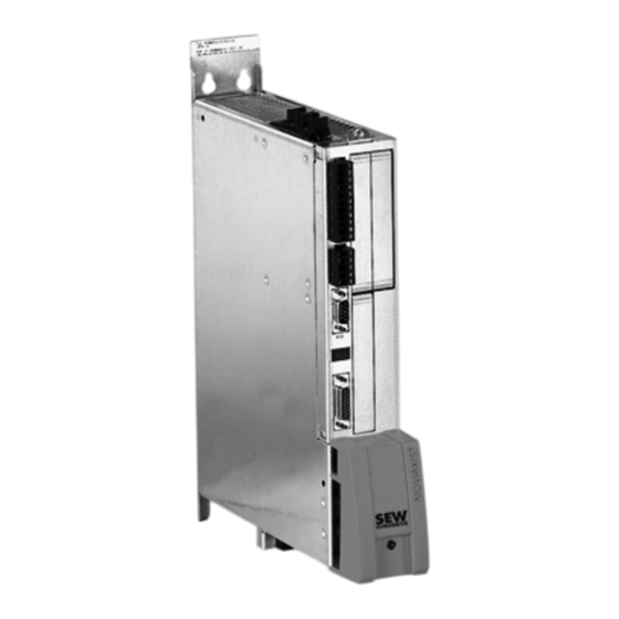
- Page 1 Drive Technology \ Drive Automation \ System Integration \ Services ® MOVIAXIS Multi-Axis Servo Inverter MXR Regenerative Power Module Manual Edition 10/2008 16607228 / EN...
- Page 2 SEW-EURODRIVE – Driving the world...
-
Page 3: Table Of Contents
Content General Information ..................5 Other applicable documentation ............... 5 Structure of the safety notes ..............5 Rights to claim under limited warranty ............6 Exclusion of liability................... 6 Safety Notes ...................... 7 General ..................... 7 Target group ..................... 7 Designated use .................. - Page 4 Content Project Planning....................62 General information ................62 Components for EMC-compliant installation........... 62 Line contactor and line fuses ..............63 Projecting the power supply..............63 Projecting the cable cross sections............64 Selecting the 24 V power supply............. 65 Projecting the emergency braking resistor..........67 Dimensioning the MXR regenerative power module.......
-
Page 5: General Information
General Information Other applicable documentation General Information MOVIAXIS® Regenerative Power Module MXR Other applicable documentation This manual describes the special properties of the MXR regenerative power module ® For all other information and functionalities of MOVIAXIS , refer to the following documents: ®... -
Page 6: Rights To Claim Under Limited Warranty
MXR regenerative power module in conjunction with the MOVIAXIS multi-axis servo inverter and to achieve the specified product characteristics and performance requirements. SEW-EURODRIVE assumes no liability for injury to persons or damage to equipment or property resulting from non-observance of the operating instructions. -
Page 7: Safety Notes
Safety Notes General Safety Notes The following basic safety notes must be read carefully to prevent injury to persons and damage to property. The operator must make sure that the basic safety notes are read and observed. Make sure that persons responsible for the plant and its operation, as well as persons who work independently on the unit, have read through the operating instructions carefully and understood them. -
Page 8: Shipping, Putting Into Storage
Safety Notes Shipping, putting into storage ® The MOVIAXIS MX multi-axis servo drives are intended for use in metal control cabi- nets. These metal control cabinets represent the necessary enclosure for the application as well as the grounding over a large area required for EMC purposes. For installation in machines, startup of the multi-axis servo inverter (meaning the start of designated use) is prohibited until it is determined that the machine meets the require- ments stipulated in the EC Directive 98/37/EC (machine directive);... -
Page 9: Electrical Connection
Safety Notes Electrical connection The following applications are prohibited unless the unit is explicitly designed for such use: • Use in potentially explosive areas. • Use in areas exposed to harmful oils, acids, gases, vapors, dust, radiation, etc. • Use in non-stationary applications that are subject to mechanical vibration and shock loads in excess of the requirements in EN 61800-5-1. -
Page 10: Unit Design
Unit Design Important information Unit Design Important information Protective measures and protective equipment have to meet the respective national regulations in effect. Follow the specific operating instructions during installation and startup of the motor and the brake! WARNING! The following "Unit design" illustrations represent the units without the provided protec- tion cover (touch guard). - Page 11 Unit Design Nameplates, unit designations 3.2.2 Unit designation of MXR regenerative power module -075 - 00 00 = Standard design XX = Special design 3-phase connection type 50 = U = AC 380 - 480 V connection voltage Power 75 KW Version 80 = Standard variant...
-
Page 12: Unit Design Of The Mxr Regenerative Power Module
Unit Design Unit design of the MXR regenerative power module Unit design of the MXR regenerative power module The following illustration shows the unit without protective cover. 3.3.1 MXR regenerative power module [15] [16] [10] [11] [14] [12] [13] 62921AXX Figure 2: Unit design of MXR regenerative power module View from top View from front... -
Page 13: Combinations Of Mxr Regenerative Power Modules With Other Units
Unit Design Combinations of MXR regenerative power modules with other units Combinations of MXR regenerative power modules with other units Unit Combination possible? Quantity – – – – In preparation In preparation – – Manual – MOVIAXIS® MXR Regenerative Power Module... -
Page 14: Standard Accessories
Unit Design Standard accessories Standard accessories Standard accessories are included with the basic unit at delivery. [16] [17] [18] [19] [20] [21] [22] [10] [11] [23] [24] [25] [26] [27] [12] [28] [13] [29] [30] [14] [31] [15] 63518axx Figure 3: Standard accessories The corresponding mating connectors for all connectors are installed at the factory. - Page 15 Unit Design Standard accessories 3.5.1 Standard accessory assignment table Dimensions Touch guard – DC link connection 76 mm – 106 mm – 136 mm – 160 mm – 226 mm Electronics shield clamp 60 mm 90 mm – 120 mm –...
-
Page 16: Installation
Installation Mechanical installation Installation Mechanical installation CAUTION! Do not install defective or damaged modules; they can possibly result in injuries or damage parts of the production system. ® • Check the unit network of the MOVIAXIS MX multi-axis servo inverter and the re- generative power module prior to installation for external damage and replace any damaged modules. - Page 17 Installation UL-compliant installation NOTICE Regenerative power module can possibly be damaged!. • Only use the stipulated connection elements and observe the prescribed tightening torques. Otherwise, excessive heat can develop which would damage the regener- ative power module. ® • MOVIAXIS MX multi-axis servo inverters are suitable for operation in voltage net- works with earthed star point (TN and TT networks), a maximum line current of 42,000 A and a maximum line voltage of AC 480 V.
-
Page 18: Installation/Removal Of The Regenerative Power Module
Installation Installation/removal of the regenerative power module Installation/removal of the regenerative power module ® Refer to the "MOVIAXIS MX Multi-Axis Servo Inverter" operation instructions for a de- scription how to install a module in an axis system and how to remove it. Adhere to the instructions for installing/removing a module. - Page 19 ® "MOVIAXIS MX Multi-Axis Servo Inverter" operating instructions. • SEW-EURODRIVE recommends to connect the emergency braking resistor as ® shown in the "MOVIAXIS MX Multi-Axis Servo Inverter" operating instructions. In- stall switch F16 close to the unit network. If an unshielded cable is used for connect- ing switch F16 with the regenerative power module, keep the length as short as pos- sible.
- Page 20 Installation Electrical installation 4.4.4 Operation of the emergency braking resistor • The connection lead to the emergency braking resistor carries a high DC voltage of about 970 V during rated operation. WARNING! The surfaces of the emergency braking resistor will reach temperatures of up to 250°C when the braking resistor is loaded with P Risk of burns and fire.
-
Page 21: Wiring Diagrams
Installation Wiring diagrams Wiring diagrams 4.5.1 General notes on the wiring diagrams NOTES The technical data of the power and control electronics connections are described in ® chapter "Technical Data" in this manual and in the "MOVIAXIS MX Multi-Axis Servo Inverter"... - Page 22 Installation Wiring diagrams Wiring of the power connections DC 24 V F16 * EMERG. STOP*** K11 ** L1 L2 L3 Line filter L1´ L2´ L3´ U1 V1 W1 Choke U2 V2 W2 L2 L3 Regenerative Axis module Axis module Axis module power module –R PE U...
-
Page 23: Terminal Assignment
Installation Terminal assignment Terminal assignment NOTES Reference potentials inside the unit: The designation of the reference potentials is listed in the following table: Designation Meaning DGND General reference potential of control electronics. There is a metallic connection to PE. BGND Reference potential for brake connection RGND Reference potential for safety relay... - Page 24 Installation Terminal assignment 4.6.1 Terminal assignment of the MXR regenerative power module NOTES The technical data of the power and control electronics connections are described in ® chapter "Technical Data" in this manual and in the "MOVIAXIS MX Multi-Axis Servo Inverter"...
- Page 25 Installation Terminal assignment Terminal Assignment Brief description X12:1 n.c. – X12:2 CAN_L CAN1 Bus Low X12:3 DGND Reference potential CAN1 bus X12:4 CAN_L CAN1 Bus Low X12:5 Unit internal SBus terminating resistor termination X12:6 DGND Reference potential CAN bus X12:7 CAN_H CAN1 Bus High X12:8...
-
Page 26: Startup
Startup General information Startup This chapter specifically describes the startup of the MXR regenerative power module. ® For detailed information on the startup of the MOVIAXIS axis system, refer to the ® "MOVIAXIS MX Multi-Axis Servo Inverter" operating instructions. General information DANGER! Uncovered power connections. -
Page 27: Settings On Regenerative Power Module For Can-Based System Bus
Startup Settings on regenerative power module for CAN-based system bus Settings on regenerative power module for CAN-based system bus The following settings are necessary: • The CAN baud rate is set using the two DIP switches S1 and S2 on the regenerative ®... - Page 28 Startup Settings on regenerative power module for CAN-based system bus 5.2.1 Example The axis address "1" is set at the MXR regenerative power module, see Figure 7. The axis addresses of all other modules are based on this setting. The following figure shows the setting of the axis addresses. Example 63194AXX Figure 7: Axis address setting...
-
Page 29: Settings On Regenerative Power Module For Ethercat-Based System Bus Xse24A
Startup Settings on regenerative power module for EtherCAT-based system bus Settings on regenerative power module for EtherCAT-based system bus XSE24A For information on the EtherCAT-based system bus XSE24A, refer to the ® "MOVIAXIS MX Multi-Axis Servo Inverter" operating instructions, chapter 3.21. Modules that are supplied with EtherCAT-based system bus XSE24A are pre-config- ured at the factory. -
Page 30: Settings On Regenerative Power Module For Ethercat Fieldbus Interface
Startup Settings on regenerative power module for EtherCAT fieldbus interface Settings on regenerative power module for EtherCAT fieldbus interface For information on the EtherCAT XFE24A fieldbus interface, refer to the ® "MOVIAXIS MX Multi-Axis Servo Inverter" operating instructions, chapter 3.20. EtherCAT EtherCAT [10]... -
Page 31: Switch-On Sequence Of Mxr Regenerative Power Module
Startup Switch-on sequence of MXR regenerative power module Switch-on sequence of MXR regenerative power module DC 24 V DC 24 V (X5a) DC 0 V Emergency stop button t *** Emergency stop relay Emerg. stop interrupted Start "Enable/upload" (X10.2) PA1/1 ** Ready for "power on"... - Page 32 Startup Switch-on sequence of MXR regenerative power module Addendum to the diagram Enable / upload The enable signal is required for operation of the MXR module. It pre-charges the DC link to about 300 V, see diagram page 31. The in-phase wiring of the components on the line end and the line voltage measure- ment are checked when the DC link voltage drops below 300 V.
-
Page 33: Process Data Assignment For Fieldbus Operation
Startup Process data assignment for fieldbus operation Process data assignment for fieldbus operation 5.6.1 Controlling the servo inverter The servo inverter is controlled via up to 16 process data input words and process data output words. Example: PA 3 PA 2 PA 1 PA 1 PA 2... - Page 34 Startup Process data assignment for fieldbus operation 5.6.2 Process output data PA Number of process data words: 1 – 16 Process data assignment PA1 (control word) Bit no. Meaning Reserved Enable / upload („1“ = enabled / upload) * Fault reset * Reserved Not assigned Not assigned...
- Page 35 Startup Process data assignment for fieldbus operation 5.6.3 Process input data PE Process data assignment PE1 (status word) Bit no. Meaning Ready for operation („1“ = ready for operation) * Ready for power on * Not assigned Not assigned Not assigned Not assigned Not assigned Not assigned...
-
Page 36: Startup Of The Mxr Using Movitools® Motionstudio
Startup Startup of the MXR using MOVITOOLS® MotionStudio ® Startup of the MXR using MOVITOOLS MotionStudio ® Selection and setup of the communication between PC and MOVIAXIS is described in ® the "MOVIAXIS Multi-Axis Servo Inverter" operating instructions, chapter "Communi- cation selection". - Page 37 Startup Startup of the MXR using MOVITOOLS® MotionStudio Step 2 Open the context menu by clicking the right mouse button and select the menu item "Startup" / "Parameter tree (Online)". 12064aen Manual – MOVIAXIS® MXR Regenerative Power Module...
- Page 38 MXR is completely started up and ready for normal operation. Deviating parameter settings for applications with special requirements are listed in chapter 'Parameter description' page 39 ff. Please contact SEW-EURODRIVE if nec- essary. Manual – MOVIAXIS® MXR Regenerative Power Module...
-
Page 39: Parameter Description
Startup Parameter description Parameter description Parameter group Parameter Function / meaning Line process values Real part of voltage phasor alpha Imaginary part of voltage phasor beta Real part of current phasor alpha Imaginary part of current phasor beta Active voltage Reactive voltage Active current Reactive voltage... - Page 40 Startup Parameter description Parameter group Parameter Function / meaning In the 'Unit status' parameter group, you can read out all information Unit status about the current unit status. In the 'Unit data' parameter group, you can read out all information Unit data about the unit variant and option cards.
- Page 41 Startup Parameter description Parameter group Parameter Function / meaning Controller parameters A current limit is set using the parameter setting "On/Off" to ensure reli- System data Activate Ixt current reduction able operation of the axes even in the case of an overload. The changeover is only implemented in "Controller inhibit active"...
- Page 42 Startup Parameter description Parameter group Parameter Function / meaning ® See "MOVIAXIS Multi-Axis Servo Inverter" project planning manual, Lock-out time parameter 9563.17 Indicates which data format is set for the CAN messages: Endianess Big Endian (Motorola format) / Little Endian (Intel format) Send PDO cyclically [ms] Indicates the intervals for sending the process data objects (PDOs).
-
Page 43: Operation
Operation General information Operation General information DANGER! Dangerous voltages at cables and motor terminals Severe or fatal injuries from electric shock. • When the unit switch is in the ON position, dangerous voltages are present at the output terminals as well as any connected cables. This also applies even when the unit is inhibited and the motor is at standstill. -
Page 44: Operating Displays And Errors Of The Mxr Regenerative Power Module
Operation Operating displays and errors of the MXR regenerative power module Operating displays and errors of the MXR regenerative power module 6.2.1 Table of displays Description Status Comment / action Displays during boot process Unit passes through several • Status: not ready. states when loading the firm- •... - Page 45 Operation Operating displays and errors of the MXR regenerative power module 6.2.2 Table of errors Error response Final error Error (P=program- Save to Error message error Possible reason for error status / code mable, history code Reset type D=default response) No error No error No response...
- Page 46 Operation Operating displays and errors of the MXR regenerative power module Error response Final error Error (P=program- Save to Error message error Possible reason for error status / code mable, history code Reset type D=default response) "Internal com- CPU has detected an internal error Inhibit output puter (traps)"...
- Page 47 Operation Operating displays and errors of the MXR regenerative power module Error response Final error Error (P=program- Save to Error message error Possible reason for error status / code mable, history code Reset type D=default response) "CRC flash- error A CRC32 error occurred during check of Inhibit output Inhibited, sys- the program code by Flash in Code RAM...
- Page 48 Operation Operating displays and errors of the MXR regenerative power module Error response Final error Error (P=program- Save to Error message error Possible reason for error status / code mable, history code Reset type D=default response) Error "External Error "External synchronization" System is not Display only Save always...
- Page 49 Operation Operating displays and errors of the MXR regenerative power module Error response Final error Error (P=program- Save to Error message error Possible reason for error status / code mable, history code Reset type D=default response) Line component The firmware has detected an error in Inhibit output Inhibited, soft- error...
-
Page 50: Technical Data
Technical Data Technical data of the MXR regenerative power module Technical Data Technical data of the MXR regenerative power module 7.1.1 General technical data Regenerative power module Unit Environmental conditions Ambient temperature (MXR) °C 0 – +45 Storage temperature °C –25 –... - Page 51 Technical Data Technical data of the MXR regenerative power module 7.1.2 Power section of the MXR regenerative power module Name- plate Regenerative power module Unit infor- mation INPUT 3 x 400 V – 3 x 480 V ±10% Supply voltage AC V line Rated power supply voltage "Maximum...
- Page 52 Technical Data Technical data of the MXR regenerative power module 7.1.3 Control section of the MXR regenerative power module ® MOVIAXIS General electronics data Regenerative power module INPUT DC 24 V voltage supply DC 24 V ± 25 % (EN 61131) COMBICON 5.08 Cross section and contacts One core per terminal: max.
- Page 53 Technical Data Technical data of the MXR regenerative power module 7.1.4 Bus communication ® MOVIAXIS Regenerative power General electronics data module CAN- or EtherCAT-based Signaling bus For the EtherCAT variant, an XSE24A or XFE24A option card is installed CAN bus to CAN specification 2.0, parts A and B, transmission technol- ogy to ISO 11898, max.
-
Page 54: Dimension Sheet Of The Mxr.. Regenerative Power Module
Technical Data Dimension sheet of the MXR.. regenerative power module Dimension sheet of the MXR.. regenerative power module 220.5 62981axx Figure 13: MXR regenerative power module dimensions Manual – MOVIAXIS® MXR Regenerative Power Module... -
Page 55: Drilling Template Of The Mxr.. Regenerative Power Module
Technical Data Drilling template of the MXR.. regenerative power module Drilling template of the MXR.. regenerative power module 06695axx Figure 14: Drilling template of MXR regenerative power module Position of tapped hole The dimensions are listed in the following table ®... -
Page 56: Technical Data Of Additional Components
Technical Data Technical data of additional components Technical data of additional components 7.4.1 NFR.. line filter for 3-phase systems UL certification is in preparation. • 3 conductor filter Structure • Metal housing Features • Design according to UL1283, IEC 60939, CSA 22.2 No. 8 •... - Page 57 Technical Data Technical data of additional components Dimension drawing NFR 111-503 (75 kW) 63623axx Figure 15: Dimension drawing of line filter for 3-phase systems Terminals for line phase measurement Manual – MOVIAXIS® MXR Regenerative Power Module...
- Page 58 Technical Data Technical data of additional components Dimension drawing NFR 075-503 (50 kW) 63624axx Figure 16: Dimension drawing of line filter for 3-phase systems Terminals for line phase measurement Manual – MOVIAXIS® MXR Regenerative Power Module...
- Page 59 Technical Data Technical data of additional components 7.4.2 NDR.. line choke Wiring diagram 62979AXX Figure 17: Wiring diagram of line choke Technical data Unit Line choke NDR 075-083 (50 kW) NDR 110-063 (75 kW) 3 x 380 V – 3 x 480 V ±10 % Supply voltage AC line Rated power supply voltage...
- Page 60 Technical Data Technical data of additional components Dimension drawing NDR 110-063 (75 kW) 11x15 W2 V2 U2 W1 V1 U1 63503AXX Figure 18: Dimension drawing of line choke Manual – MOVIAXIS® MXR Regenerative Power Module...
- Page 61 Technical Data Technical data of additional components Dimension drawing NDR 075-083 (50 kW) 11x15 W2 V2 U2 W1 V1 U1 62980AXX Figure 19: Dimension drawing of line choke Manual – MOVIAXIS® MXR Regenerative Power Module...
-
Page 62: Project Planning
Interference Compliance with category "C2" according to EN 61800-3 has been tested on a specified emission category test setup. SEW-EURODRIVE can provide detailed information on request. WARNING! This product can cause high-frequency interferences in residential areas which can re- quire measures for interference suppression. -
Page 63: Line Contactor And Line Fuses
Project Planning Line contactor and line fuses Line contactor and line fuses Line contactor • Only use line contactors in utilization category AC-3 (IEC 158-1). • The contactor K11 is designed for switching the MXR on and off only. NOTICE •... -
Page 64: Projecting The Cable Cross Sections
The cable length between the line contactor and the line filter may not exceed 5 m, see also wiring diagram page 22. Cable cross sec- SEW-EURODRIVE recommends the following cable cross sections and fusing, assum- tions and fuses ing the use of single-core copper cables with PVC insulation laid in cable ducts, an am- bient temperature of 40 °C and rated system currents of 100 % of the rated unit current:... -
Page 65: Selecting The 24 V Power Supply
Project Planning Selecting the 24 V power supply Selecting the 24 V power supply The current path and power ratios present when switching on the 24 V voltage supply are shown in Figure 20 . The current path is basically divided into 3 time ranges. ≈... - Page 66 Project Planning Selecting the 24 V power supply Rated current Max. input cur- Input pulse Supply voltage Input capaci- Unit type [A] / rated rent [A] / power duration t Electronics [V] tance C [µF] power P [ms] MXP BG1 0.5 / 12 0.3 / 7 18 - 30...
-
Page 67: Projecting The Emergency Braking Resistor
Project Planning Projecting the emergency braking resistor Projecting the emergency braking resistor 8.7.1 Notes on the emergency braking resistor NOTES ® Das Under normal operating conditions, the MOVIAXIS MXR regenerative power module feeds regenerative energy that exceeds the DC link buffer into the supply sys- tem. - Page 68 Project Planning Projecting the emergency braking resistor WARNING! The surfaces of the emergency braking resistors get very hot when the braking resis- tors are loaded with P rated Risk of burns and fire. • Choose a suitable installation location. Emergency braking resistors are usually mounted on top of the control cabinet.
- Page 69 Project Planning Projecting the emergency braking resistor Condition 2 The previously determined amount of regenerative energy W is the basis for generatorisch checking whether the emergency braking resistor can dissipate this amount without thermal overload. ≥ generatorisch 63175AXX Max. amount of energy that the emergency braking resistor can absorb Total amount of energy of the application regenerated during emergency braking.
- Page 70 Project Planning Projecting the emergency braking resistor Unit temperature WARNING! The surfaces of the emergency braking resistors get very hot when the braking resis- tors are loaded with P rated Risk of burns and fire. • Choose a suitable installation location. Emergency braking resistors are usually mounted on top of the control cabinet.
- Page 71 Project Planning Projecting the emergency braking resistor Selection table Taking the max. regenerative braking power and regenerative energy generated in the machine or system into account, you can select an emergency braking resistor from the resistors listed in the table. Use the SEW Workbench software for project planning. Trip cur- Resistance Duration...
-
Page 72: Dimensioning The Mxr Regenerative Power Module
Project Planning Dimensioning the MXR regenerative power module Dimensioning the MXR regenerative power module The size of a regenerative power module is determined by: • The total actual power of all axis modules: P < P , motor and regenerative. •... -
Page 73: 8.10 Overload Capacity
The ramp time, In case of ramp times shorter than the values in the table below, a braking resistor is mandatory. • The braking resistor. SEW-EURODRIVE recommends the following braking resistors: MXR 50 kW MXR 75 kW BW012-015 BW006-025-01 Overload data in % must be applied to the rated unit power at the respective line voltage, see chapter "Output in case of lower line voltage", page 72. -
Page 74: Integrating A Regenerative Power Module In A Unit Network
Project Planning Integrating a regenerative power module in a unit network 8.11 Integrating a regenerative power module in a unit network NOTICE Please note that no more than 8 axis modules can be used in a network. MXA MXA MXA MXA 50 kW 100 A 64 A... -
Page 75: 8.12 Power Supply
Project Planning Power supply 8.12 Power supply The following schematic example illustration shows a typical arrangement of ® MOVIAXIS modules in an axis system. It shows the connection of • The DC link, • The signaling bus • And the DC 24 V voltage supply. Terminating Signal bus resistor... -
Page 76: Index
Index Index Installation ............8 Numerics Electrical ..........18 24 V power supply, selection ......65 Mechanical..........16 Installation of regenerative power module ..18 Integrating a regenerative power Accessories............ 14 module in a unit network ........ 74 Accessory assignment table ......15 Additional components........ - Page 77 Index Operation of MXR in case of line faults ... 70 Output in case of lower line voltage..72 UL-compliant installation ........ 16 Overload capacity........73 Unit design ............. 10 Peak braking power......... 68 Unit design of MXR ........12 Power supply ...........
- Page 79 SEW-EURODRIVE – Driving the world...
- Page 80 Internet, available Anywhere. today. around the clock. SEW-EURODRIVE GmbH & Co KG P.O. Box 3023 · D-76642 Bruchsal / Germany Phone +49 7251 75-0 · Fax +49 7251 75-1970 sew@sew-eurodrive.com www.sew-eurodrive.com...
Need help?
Do you have a question about the MOVIAXIS MXR and is the answer not in the manual?
Questions and answers