
Related Manuals for SEW-Eurodrive MAXOLUTION MAXO-MS


Summary of Contents for SEW-Eurodrive MAXOLUTION MAXO-MS
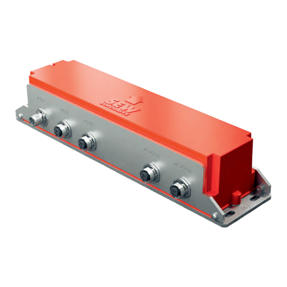
- Page 1 *26868113_0321* Drive Technology \ Drive Automation \ System Integration \ Services Assembly and Operating Instructions ® MAXOLUTION System Solution MAXO-MS/M/SM-GIOP Sensor Module Edition 03/2021 26868113/EN...
- Page 2 SEW-EURODRIVE—Driving the world...
-
Page 3: Table Of Contents
Table of contents Table of contents General information........................ 5 About this documentation .................... 5 Other applicable documentation .................. 5 Structure of the safety notes ................... 5 Decimal separator in numerical values ................ 6 Rights to claim under limited warranty ................ 6 Product names and trademarks.................. 6 Copyright notice ...................... 6 Safety notes .......................... - Page 4 Table of contents Read head for RFID transponder.................. 30 Dimension Sheet...................... 31 Approvals .......................... 32 USA/Canada ......................... 32 Europe .......................... 32 ® MAXOLUTION Competence Center .................. 34 Assembly and Operating Instructions – MAXO-MS/M/SM-GIOP Sensor Module...
-
Page 5: General Information
General information About this documentation General information About this documentation The documentation at hand is the original. This documentation is an integral part of the product. The documentation is intended for all employees who perform work on the product. Make sure this documentation is accessible and legible. Ensure that persons respon- sible for the systems and their operation as well as persons who work on the product independently have read through the documentation carefully and understood it. -
Page 6: Decimal Separator In Numerical Values
General information Decimal separator in numerical values Meaning of the hazard symbols The hazard symbols in the safety notes have the following meaning: Hazard symbol Meaning General hazard 1.3.3 Structure of embedded safety notes Embedded safety notes are directly integrated into the instructions just before the de- scription of the dangerous action. -
Page 7: Safety Notes
Safety notes Preliminary information Safety notes Preliminary information The following general safety notes serve the purpose of preventing injury to persons and damage to property. They primarily apply to the use of products described in this documentation. If you use additional components, also observe the relevant warning and safety notes. -
Page 8: Designated Use
Safety notes Designated use Specialist for elec- Any electrotechnical work may be performed only by electrically skilled persons with a trotechnical work suitable education. Electrically skilled persons in the context of this documentation are persons who are familiar with electrical installation, startup, troubleshooting, and main- tenance of the product who possess the following qualifications: •... -
Page 9: Network Security And Access Protection
Safety notes Network security and access protection Observe the following restrictions: • Do not open the product. Safe and fault-free operation can no longer be ensured if you open the product. In case of service, send your product back to SEW‑EURODRIVE. Your right to claim under warranty no longer applies if you open the product. -
Page 10: Electrical Installation
Safety notes Electrical installation Electrical installation The preventive measures and protection devices must comply with the applicable reg- ulations (e.g. EN 60204-1 or EN 61800-5-1). Startup and operation Damaged products Never install damaged products. Submit any complaint to the shipping company im- mediately in the event of transportation damage. -
Page 11: Device Structure
Device structure Type designation Device structure Type designation ® MAXO MAXOLUTION system solution – Mobile system Module Sensor module – Design with the following combination options: Acceleration and rotation rate sensor Inductive Optical (connection available for external optical track guidance) RFID Overview of designs Designation... -
Page 12: Nameplate
Device structure Nameplate Nameplate Type: FCC ID: D-76646 Bruchsal Made in Germany IP = 33552897163 Product designation Version Depending on the device design, the following information is listed on the main name- plate: Value Specification Type Type designation Part number (for customer-specific products) Production number FCC ID Radio approval for USA/Canada... -
Page 13: Device Overview
Device structure Device overview Device overview X 4 2 5 1 _ 1 1 X 4 2 5 1 _ 1 2 X 4 0 3 X 4 1 1 1 X 4 1 0 X 1 5 1 33692952587 ®... -
Page 14: Operating Principle
Device structure Operating principle Operating principle The following figure shows the block diagram of the sensor module: EtherCAT® RS422 μC DC-24-V RFID chip ind. track sensor RFID antenna 33985535883 The sensor module is used in a mobile assistant. It consists mainly of the following components: Communication interfaces Rotation rate and acceleration sensors... -
Page 15: Mechanical Installation
Mechanical installation Track and vehicle geometry Mechanical installation Track and vehicle geometry 4.1.1 Distance designation The following figure shows the vehicle from below (in the direction of travel) with the designation of the distances: 34148228235 Sensor module Distance R between the sensor module (SM) and the steered axis Motor Distance of the two drive wheels Tire radius... - Page 16 Mechanical installation Track and vehicle geometry 4.1.3 Minimum permitted curve radius The smallest possible curve radius r that can be traveled at v is calculated us- Kurve,min ing the actual distance R: Kurve ,min 0 08 2561110795 4.1.4 Speed reduction in tight curves For curve radii r <...
-
Page 17: Minimum Clearances
Mechanical installation Minimum clearances Minimum clearances SEW‑EURODRIVE recommends observing the following clearances when mounting the device: 33693137803 The following table lists the minimum clearances: Clearance Function Clearance Distance to metallic components. This way, ≥ 50 mm you can avoid a reduction of the range when reading an RFID transponder. - Page 18 Mechanical installation Travel direction INFORMATION Reverse travel is not possible. Assembly and Operating Instructions – MAXO-MS/M/SM-GIOP Sensor Module...
-
Page 19: Project Planning Notes On Inductive Track Guidance
Mechanical installation Project planning notes on inductive track guidance Project planning notes on inductive track guidance 4.4.1 Distances for line cable routing Inductive track guidance is used with line cables (round or wedge-shaped) that are routed at a distance of 140 mm. The following figure shows the distances that must be observed when mounting the sensor module using a round line cable as an example: 25 mm... - Page 20 Mechanical installation Project planning notes on inductive track guidance ® The MOVITRANS THM10E pick-ups may be installed before and/or after the sensor module, taking the minimum clearances into account (see "Minimum clear- ances" (→ 2 17)). Assembly and Operating Instructions – MAXO-MS/M/SM-GIOP Sensor Module...
-
Page 21: Project Planning Notes, Rfid System
Mechanical installation Project planning notes, RFID system Project planning notes, RFID system The following figure shows the sensor module, the components for installing the transponder and the required distance to the hall floor: 2 5 m m 34161143179 [1] Sensor module [2] Closing plug for assembly sleeve [3] Transponder [4] Assembly sleeve for transponder... - Page 22 Mechanical installation Project planning notes, RFID system INFORMATION Faulty reading of transponders ü At a distance of 25 mm, safe reading of the transponder (IQC22‑22-T9) is guaran- teed for speeds of up to 2 m/s if the following conditions are met: • Correct installation of the recommended transponder components.
-
Page 23: Mounting The Device
Mechanical installation Mounting the device Mounting the device The device has 2 slotted holes [4] on both sides. You can mount the device [3] using the slotted holes [4] and 4 cap screws [6]. • Use screws [6] of suitable length to mount the device [3]. •... -
Page 24: Electrical Installation
Electrical installation Electrical connections Electrical installation Electrical connections 5.1.1 Representation of connections The wiring diagrams show the contact end of the connections. ® PLUS 5.1.2 X4251_11/12: EtherCAT /SBus interface Function ® PLUS EtherCAT /SBus Connection type Connection M12, 4-pin, female, D-coded Connection diagram Name Function... - Page 25 Electrical installation Electrical connections Name Function +24V DC 24 V supply n.c. Not assigned 0V24 0V24 reference potential n.c. Not assigned Transmit line (+) Receive line (+) Transmit line (-) Receive line (-) 5.1.4 X4111_11/12: CAN interface Function CAN interface Connection type Connection M12, 5-pin, female, A-coded Connection diagram Name...
- Page 26 Electrical installation Electrical connections Connection diagram Name Function +24V DC 24 V supply n.c. Not assigned 0V24 0V24 reference potential n.c. Not assigned Assembly and Operating Instructions – MAXO-MS/M/SM-GIOP Sensor Module...
- Page 27 Service Waste disposal Service Waste disposal Dispose of the product and all parts separately in accordance with their material struc- ture and the national regulations. Put the product through a recycling process or con- tact a specialist waste disposal company. If possible, divide the product into the follow- ing categories: •...
-
Page 28: Return Information
Return Information – Project identification / Projektidentifikation Proj. number Proj. name SEW-EURODRIVE Proj. name customer Serial number, unit / Seriennummer, Gerät Customer reference / Kundenreferenz Local contact for inquiries / Ansprechpartner vor Ort für Rückfragen Phone / Telefon E-mail / E-Mail... -
Page 29: Technical Data
Technical data General Technical data General General Ambient temperature +5 °C to +40 °C (non-condensing, no condensation) Storage temperature and -25 °C to +70 °C transportation Climate class (EN 60721-3-3) Voltage supply DC 24 V Max. power/current consump- 12 W/0.5 A tion (without external optical track guidance) Mass 28279883 (GIP) 620 g 28272528 (GIOP) 632 g Degree of protection IP54 (according to EN 60529) Installation altitude (industry... -
Page 30: Read Head For Rfid Transponder
Technical data Read head for RFID transponder Rotation rate and acceleration sensors Rotation rate sensor Acceleration sensors (g = 9.81 m/s Noise ±0.2°/s 5 mg (rms value at 57 Hz) Bandwidth (-3 dB) 13 Hz and 57 Hz Start time 350 ms Read head for RFID transponder Read head for RFID transponder Operating frequency 13.56 MHz Transmission rate... -
Page 31: Dimension Sheet
Technical data Dimension Sheet Dimension Sheet Ø5.5 35.9 35.9 35.9 35.9 33702240139 Assembly and Operating Instructions – MAXO-MS/M/SM-GIOP Sensor Module... -
Page 32: Approvals
Approvals USA/Canada Approvals USA/Canada Changes or modif ications not expressively approved by SEW-EURODRIVE void the user’s authority to operate the equipment. SEW-EURODRIVE GmbH & Co. KG Sensor module • MAXO-MS/M/SM-GIOP Variant with connection for optical track guidance • MAXO-MS/M/SM-GIP Variant without connection for optical track guidance... - Page 33 Approvals Europe 8.2.1 Declaration of conformity The latest declaration of conformity is available on the SEW‑EURODRIVE website. Do the following: 1. Call up the SEW‑EURODRIVE website at https://www.sew‑eurodrive.de/. If neces- sary, you can change the view using the country and language selection. 2.
-
Page 34: Maxolution Competence Center
Fax +91 265 3045300 POR Ramangamdi • Vadodara - 391 243 http://www.seweurodriveindia.com Gujarat salesvadodara@seweurodriveindia.com Italy Solaro SEW-EURODRIVE S.a.s. di SEW S.r.l. & Co. Tel. +39 02 96 980229 Via Bernini,12 Fax +39 02 96 980 999 20033 Solaro (Milano) http://www.sew-eurodrive.it milano@sew-eurodrive.it... - Page 35 ® MAXOLUTION Competence Center South Korea Ansan SEW-EURODRIVE Korea Co., Ltd. Tel. +82 31 492-8051 7, Dangjaengi-ro, Fax +82 31 492-8056 Danwon-gu, http://www.sew-eurodrive.kr Ansan-si, Gyeonggi-do, Zip 425-839 master.korea@sew-eurodrive.com Sweden Jönköping SEW-EURODRIVE AB Tel. +46 36 34 42 00 Gnejsvägen 6-8 Fax +46 36 34 42 80 553 03 Jönköping...
- Page 40 SEW-EURODRIVE—Driving the world SEW-EURODRIVE GmbH & Co KG Ernst-Blickle-Str. 42 76646 BRUCHSAL GERMANY Tel. +49 7251 75-0 Fax +49 7251 75-1970 sew@sew-eurodrive.com www.sew-eurodrive.com...
Need help?
Do you have a question about the MAXOLUTION MAXO-MS and is the answer not in the manual?
Questions and answers