
Subscribe to Our Youtube Channel
Related Manuals for Alcatel-Lucent OmniAccess 5840


Summary of Contents for Alcatel-Lucent OmniAccess 5840
- Page 1 Manual Alcatel-Lucent Enterprise OA58XX Router Installation Manual Copyright© ALU-DM693-I Version 13.1 05/2016 Alcatel-Lucent Enterprise OA58XX Router...
- Page 2 This publication is subject to change. Alcatel-Lucent Enterprise offers no warranty whatsoever for information contained in this manual. Alcatel-Lucent Enterprise is not liable for any direct, indirect, collateral, consequential or any other damage connec- ted to the delivery, supply or use of this manual.
-
Page 3: Table Of Contents
Table of Contents Alcatel-Lucent Enterprise Table of Contents Related Documents....... . . 1 Chapter 1 About This Guide . - Page 4 Table of Contents Alcatel-Lucent Enterprise 3.6.5 Connecting the Wireless WAN Antenna* ......3.6.6 Connecting the Wireless LAN Antenna ......
- Page 5 Table of Contents Alcatel-Lucent Enterprise A.5.3 Wireless WAN Interface** Not available in all models....A.5.4 Wireless LAN Interface ....... .
- Page 6 Table of Contents Alcatel-Lucent Enterprise OA58XX Router...
-
Page 7: I Related Documents
Related Documents Alcatel-Lucent Enterprise I Related Documents ALU-Dm748-I Software Updating ALU-Dm781-I Cellular Interface. ALU-Dm776-I Power Over Ethernet. OA58XX Router... -
Page 8: Chapter 1 About This Guide
1.7 Technical Support Alcatel-Lucent Enterprise technical support is committed to resolving our customer’s technical issues in a timely manner. Customers with inquiries should contact us at: Contact information:... - Page 9 1 About This Guide Alcatel-Lucent Enterprise Asia Pacific +65 6240 8484 Web: http://service.esd.alcatel-lucent.com Email: esd.support@alcatel-lucent.com OA58XX Router...
-
Page 10: Oa58Xx Routers
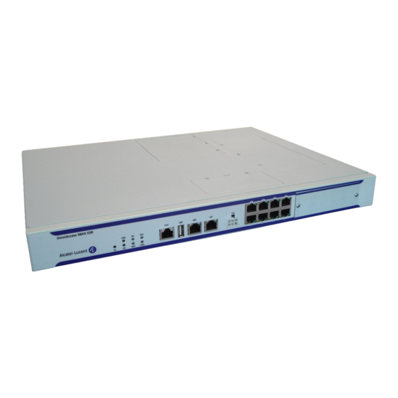
Chapter 2 OA58XX Routers The OA58XX router family consists of the following devices: • OmniAccess 5840 OA5840 ESR modular chassis base model has 2 x GigE WAN, 8 x GigE LAN, 1 x DSL slot, 1 x AIC slot. HW ready for 802.11bgn (activated by license). -
Page 11: Components And Power Supply
3 Components and Power Supply Alcatel-Lucent Enterprise Chapter 3 Components and Power Supply The following chapter provides detailed information on the chassis of the OA58XX router family and its components. This information includes: • Components. • Expansion modules. • Information on assembly. - Page 12 3 Components and Power Supply Alcatel-Lucent Enterprise Below, you can find a description of each LED: Front panel LEDs table Description State Power-on indicator. It lights up when connected to the power. Shows the state of the device con- Off -> Device not connected, not de- nected to the USB connector tected or incompatible.
-
Page 13: Rear Panel
3 Components and Power Supply Alcatel-Lucent Enterprise lished. In addition to the LEDs described in the above table, the front panel also has the LEDs for the Gigabit and Switch Ethernet interfaces. Gigabit ethernet interface LEDs Fig. 3: Below, you will find information on the LEDs associated to the Gigabit Ethernet interfaces:... -
Page 14: Top Panel
3 Components and Power Supply Alcatel-Lucent Enterprise Rear panel Fig. 5: The rear panel elements are as follows: Rear panel connectors table Item Description WWAN Diversity. Auxiliary antenna for the OA58XX cellular module. This module is optional, so your device may not have any antennas. -
Page 15: Side Panel
3 Components and Power Supply Alcatel-Lucent Enterprise 3.1.4 Side Panel The following figure shows the side panel. Side panel Fig. 7: The side panel elements are as follows: Side panel elements table Item Description Slots for the screws to assemble this in rack. - Page 16 3 Components and Power Supply Alcatel-Lucent Enterprise Remove the flap’s screws from the top panel Fig. 9: (4) Once the screws have been removed, slide the flap and lift it (making sure no grooves attach the flap to the top panel) to remove it.
- Page 17 3 Components and Power Supply Alcatel-Lucent Enterprise Reposition the cover on SLOT 1 Fig. 13: (10) Reposition the top panel flap and screw it into place using the screws. Please see Fig. 14 on page 11. Rearrange the screws on the top panel flap Fig.
-
Page 18: Slot 2 - Expansion Slot
3 Components and Power Supply Alcatel-Lucent Enterprise Current production date: 11 23 Current software license: 28 60 S/N: 754/00111 BIOS MAC Add: 00-a0-26-a2-00-2c >>..TRYING APP DUMP (CONFIGURED) appcode1.bin ver.: 0.11.0.1 0.0.0.0 APP0 CODE DUMP. Mode:0........APP0 DATA DUMP.......... - Page 19 3 Components and Power Supply Alcatel-Lucent Enterprise AIC Expansion board: Location Fig. 16: (6) Using a screwdriver, remove the cover covering the expansion slot. This cover is located on the rear panel. Push this out. Removing the SLOT 2 cover Fig.
- Page 20 3 Components and Power Supply Alcatel-Lucent Enterprise persists, please contact your usual supplier. (13) Connect a terminal to the console and check that the device detects the AIC board: ************************************************** ************************************************** ************************************************** BIOS CODE DUMP....BIOS DATA DUMP..End of BIOS dump FLASH BIOS CODE VERSION: 02.01...
-
Page 21: Slot 3 - Expansion Slot
3 Components and Power Supply Alcatel-Lucent Enterprise Press any key to get started 3.2.3 SLOT 3 – Expansion Slot SLOT 3 is located in the middle of the device’s Rear Panel on page 7. Insert an xDSL expansion board in this SLOT. - Page 22 3 Components and Power Supply Alcatel-Lucent Enterprise Remove the SLOT 3 cover Fig. 24: (8) Place the xDSL expansion card so that this firstly adjusts to the space on the device rear panel and sub- sequently to the motherboard connection. This operation must be carried out carefully, without forcing any piece or part of the device.
-
Page 23: Installation In A Rack
3 Components and Power Supply Alcatel-Lucent Enterprise (Vendor: 0x10B5, Device: 0x8112) (Subs. Vendor: 0x0000, Subs. Device: 0x0000) Slot 1 - PCI device: bridge (Bus: 12, Device: 14, Function: 0) (Vendor: 0x1057, Device: 0x18C1) (Subs. Vendor: 0x5444, Subs. Device: 0x1700) Current production date: 11 23... -
Page 24: Power Source
3 Components and Power Supply Alcatel-Lucent Enterprise Device with the strips Fig. 27: 3.4 Power Source The OA58XX router is powered with an internal power source. Additionally, the OA58XX router can incorporate an optional card to inject PoE through the 8-port Switch. In this case, the device has to be connected to an AC/DC external power source to power said module. -
Page 25: Poe Source
3 Components and Power Supply Alcatel-Lucent Enterprise 3.4.1.1 Connecting • Ensure that the on/off power supply switch is in the OFF position. • Connect all data cables. • Connect the power supply to the device. • Set the device’s on/off power supply switch in the ON position. - Page 26 3 Components and Power Supply Alcatel-Lucent Enterprise APC PoE card: Location Fig. 30: (6) Place the APC PoE card so that it matches the two connectors. This operation must be carried out carefully, without forcing any piece or part of the device. Check that the card is clearly settled over the connectors.
-
Page 27: Microswitches
3 Components and Power Supply Alcatel-Lucent Enterprise SWITCH(8) 10/100 CARD 0x18 POE CARD 1 SECURITY ENGINE Slot 1 - PCI device: PowerPC processor, Host (Bus: 10, Device: 0, Function: 0) (Vendor: 0x1957, Device: 0x0100) (Subs. Vendor: 0x0000, Subs. Device: 0x0000) -
Page 28: Procedure To Ignore The Configuration
3 Components and Power Supply Alcatel-Lucent Enterprise The default configuration for the router establishes the access IP and mask address as follows: • IP address: 192.168.1.1 • IP mask: 255.255.255.0 Note Some devices leave the factory with customized settings. This personalization can mean that the de- fault configuration is different from the one shown above. -
Page 29: Data Connection
3 Components and Power Supply Alcatel-Lucent Enterprise (Vendor: 0x1057, Device: 0x18C1) (Subs. Vendor: 0x5444, Subs. Device: 0x1700) Current production date: 11 23 Current software license: 28 60 S/N: 754/00111 BIOS MAC Add: 00-a0-26-a2-00-2c >> ..TRYING APP DUMP (CONFIGURED) appcode1.bin ver.: 0.11.0.1 0.0.0.0 APP0 CODE DUMP. -
Page 30: Connecting An Usb 3G Device (Usb Connector)
3 Components and Power Supply Alcatel-Lucent Enterprise 3.6.3 Connecting an USB 3G device (USB connector) The OA58XX router has an USB HOST 2.0 interface with a type A connector that allows USB 3G modems to be con- nected. The interface is activated through the corresponding software license. -
Page 31: Connecting The Wireless Lan Antenna
3 Components and Power Supply Alcatel-Lucent Enterprise To achieve optimum performance, the installed radio frequency accessories (antennas and cables) should be those recommended by ALU. 3.6.5.1 Positioning the antenna The antenna orientation and its location with respect to other wireless devices and radiation devices (such as com- munication devices, personal computers, etc.) can influence significantly the device performance. -
Page 32: Installing The Sim Card
3 Components and Power Supply Alcatel-Lucent Enterprise 3.7 Installing the SIM card The OA58XX router may optionally include a Wireless WAN interface that requires one SIM card to be inserted into the device. There are certain services (CDMA) provided by several carriers in some countries that do not require SIM cards. -
Page 33: Optional Storage
3 Components and Power Supply Alcatel-Lucent Enterprise Internal SIM tray Fig. 41: In order to insert a SIM card in the internal tray, locate the retaining flange (metal fastening with OPEN and LOCK on it) so you can open the tray and place the SIM card on it. Then: (1) Push the fastening in the direction indicated by the arrow with the word OPEN. -
Page 34: Procedure To Install A Flash Memory Expansion Usb
3 Components and Power Supply Alcatel-Lucent Enterprise and handled. Open up the device. To do this, you need to remove the top cover which is secured through screws located on the rear and side of the device. (3) Once the screws have been removed, slide the flap towards the rear panel and lift it. Place it in a safe location. - Page 35 3 Components and Power Supply Alcatel-Lucent Enterprise USB connector for flash memory expansion Fig. 44: (5) Close the device with the cover. Secure the cover with the screws. (6) Connect and switch on the device, as described in section Connecting on page 19.
-
Page 36: Chapter 4 Compliance
4 Compliance Alcatel-Lucent Enterprise Chapter 4 Compliance 4.1 Manufacturer Information Teldat Brand Manufacturer Teldat S.A. Country Spain Postal Address Isaac Newton, 10 Parque Tecnológico de Madrid, 28760 Tres Cantos, Madrid, Spain International Phone +34 91 807 65 65 OA58XX Router... -
Page 37: Safety Warnings
4 Compliance Alcatel-Lucent Enterprise 4.2 Safety Warnings Connecting Disconnecting OA58XX Router... - Page 38 4 Compliance Alcatel-Lucent Enterprise OA58XX Router...
- Page 39 4 Compliance Alcatel-Lucent Enterprise OA58XX Router...
-
Page 40: Weee Information
4 Compliance Alcatel-Lucent Enterprise 4.3 WEEE Information The waste container symbol with the >X< indicates that the device must be dis- posed of separately from normal domestic waste at an appropriate waste disposal facility at the end of its useful service life. -
Page 41: China Rohs
4 Compliance Alcatel-Lucent Enterprise 4.5 China RoHS Teldat products also comply with the requirements set forth in China's Environ- mental Declaration and carry the "EFUP 10" label shown on the left. OA58XX Router... -
Page 42: Ec Declaration Of Conformity
In accordance to article 10 of 2014/53/EU, we inform you that national restrictions and requirements may apply when it comes to authorization. These can evolve with time. Alcatel-Lucent Enterprise recommends that you check with local authorities what the latest status of national regulation is. -
Page 43: Operating Frequency
4 Compliance Alcatel-Lucent Enterprise 4.9 Operating Frequency To check the operating frequencies working in the device, see WIFI Specifications on page 44 4.10 FCC Statement 4.10.1 Federal Communications Commission Interference This equipment has been tested and found to comply with the limits for a Class A digital device, pursuant to Part 15 of the FCC Rules. -
Page 44: Appendix A Technical Information
Technical Information Alcatel-Lucent Enterprise Appendix A Technical Information A.1 Troubleshooting The following table can help you solve problems when installing the device. If you cannot solve the problem, contact your dealer for more information. Symptom Solution None of the LEDs lights up on Check the power supply to the device (power source, ON/OFF switch, main power the device. -
Page 45: Connecting To The Device
Technical Information Alcatel-Lucent Enterprise A.3 Connecting to the device A.3.1 Connecting using the local console (Conf connector) The OA58XX router has a RJ45 female connector on the front panel known as “ Conf .” , which provides access to the device local console. -
Page 46: Lan (Ge X) Connector
Technical Information Alcatel-Lucent Enterprise A.4.1 LAN (GE x) Connector RJ45 LAN RJ45 PIN FE Signals GE Signals BI-DA+ BI-DA+ BI-DA- BI-DA- BI-DB+ BI-DB+ BI-DC+ BI-DC- BI-DB- BI-DB- BI-DD+ BI-DD- A.4.2 WWAN Connectors* Internal RF in/out External A.4.3 WLAN Connectors Internal... -
Page 47: Configuration Connector
Technical Information Alcatel-Lucent Enterprise A.4.4 Configuration Connector RJ45 CONFIGURATION CONF A.5 Technical Specifications A.5.1 Hardware Architecture PROCESSOR FreeScale QorlQ P1020E MEMORY 512 Mbytes in DDR3 STORAGE UNIT FLASH NOR Memory (64 Mbytes) EEPROM 2Kbytes, NVRAM 128Kbytes A.5.2 LAN Interfaces PROTOCOLS Ethernet (802.3) - Page 48 Technical Information Alcatel-Lucent Enterprise A.5.3 Wireless WAN Interface* • HSPA: STANDARDS/ Triband Version: 850, 1900 & 2100 MHz SPEED Dualband Version: 900 & 2100 MHz Forward link up to 7.2 Mbps; reverse link up to 5.76 Mbps • UMTS: Triband Version: 850, 1900 & 2100 MHz Dualband Version: 900 &...
- Page 49 Technical Information Alcatel-Lucent Enterprise A.5.7 Dimensions and weight TYPE Box to assemble in a Rack 1U high LENGTH x WIDTH x HEIGHT 440 x 378.71 x 43.2 mm WEIGHT 4.0 kg A.5.8 Environmental Specifications ENVIRONMENTAL TEMPER- On: 5º to 50 ºC.
-
Page 50: Appendix B Radio Information
Radio Information Alcatel-Lucent Enterprise Appendix B Radio Information B.1 WIFI Specifications The Wifi Radio communications is in conformity with the standards 802.11a/b/g/n This product is supplied with antennas EDA-8709-25GR2-A9 model number. Do not choose another antennas for ful- filling the regulations. - Page 51 Radio Information Alcatel-Lucent Enterprise 802.11n (HT40) at MCS0 5150 ~ 5725: +22 dBm OA58XX Router...
Need help?
Do you have a question about the OmniAccess 5840 and is the answer not in the manual?
Questions and answers