Alcatel-Lucent OmniSwitch 6860 Hardware User's Manual
Hide thumbs
Also See for OmniSwitch 6860:
- Hardware user's manual (122 pages) ,
- Troubleshooting manual (148 pages) ,
- Hardware user's manual (122 pages)

Related Manuals for Alcatel-Lucent OmniSwitch 6860


Summary of Contents for Alcatel-Lucent OmniSwitch 6860
- Page 1 Part No. 060390-10, Rev. E May 2017 OmniSwitch 6860/6860E Hardware Users Guide enterprise.alcatel-lucent.com...
- Page 2 The specifications described in this guide are subject to change without notice. enterprise.alcatel-lucent.com Alcatel-Lucent and the Alcatel-Lucent Enterprise logo are trademarks of Alcatel-Lucent. To view other trademarks used by affiliated companies of ALE Holding, visit: enterprise.alcatel-lucent.com/trademarks. All other trademarks are the property of their respective owners. The information presented is subject to change without notice.
-
Page 3: Table Of Contents
How is the Information Organized? ................... x Documentation Roadmap ....................xi Related Documentation ....................xiii Technical Support ......................xiv Chapter 1 OmniSwitch 6860 ...................... 1-1 OmniSwitch 6860 Availability Features .................1-3 Power Supply Redundancy ..................1-3 Hot-Swapping ......................1-3 Hardware Monitoring ....................1-4 Chapter 2 Getting Started ......................2-1 Installing the Hardware ....................2-1... - Page 4 Specifying the Switch’s Location ..............2-10 Viewing Your Changes ..................2-11 Saving Your Changes .....................2-11 Chapter 3 Chassis and Power Supplies ..................3-1 OmniSwitch 6860 Chassis Details ..................3-2 OmniSwitch 6860-24 ....................3-2 OS6860-24 Front Panel ..................3-2 OS6860-24 Rear Panel ..................3-2 OS6860-24 Chassis Specifications ..............3-3 OmniSwitch 6860-48 ....................3-4 OS6860-48 Front Panel ..................3-4...
- Page 5 Managing Power over Ethernet (PoE) ..............4-1 In This Chapter ........................4-2 Power over Ethernet Specifications ................4-3 Viewing Power Supply Status ..................4-3 Viewing PoE Status ....................4-4 Power over Ethernet Defaults ..................4-4 Understanding and Modifying the Default Settings ..........4-5 OmniSwitch 6860 Hardware Users Guide May 2017...
- Page 6 Wrist Strap Warning ..................A-10 Instrucciones de seguridad en español ................. A-11 Advertencia sobre el levantamiento del chasis ..........A-11 Advertencia de las tapaderas en blanco ............A-11 Advertencia en caso de tormenta eléctrica ............. A-11 OmniSwitch 6860 Hardware Users Guide May 2017...
- Page 7 Advertencia sobre una apropiada conexión a tierra ........A-12 Leer “información importante de seguridad” ..........A-12 Advertencia de acceso restringido ..............A-12 Advertencia de pulsera antiestática ..............A-12 Clase de seguridad ..................A-12 Advertencia de fuentes de poder ..............A-12 OmniSwitch 6860 Hardware Users Guide May 2017...
- Page 8 Contents viii OmniSwitch 6860 Hardware Users Guide May 2017...
-
Page 9: About This Guide
About This Guide This OmniSwitch 6860 Hardware Users Guide describes OmniSwitch 6860 switch components and basic switch hardware procedures. Supported Platforms The information in this guide applies only to OmniSwitch 6860(E) switches. Who Should Read this Manual? The audience for this users guide is network administrators and IT support personnel who need to configure, maintain, and monitor switches and routers in a live network. -
Page 10: What Is In This Manual
Each chapter in this guide focuses on a specific hardware component or a set of hardware components. All descriptive, technical specification, and procedural information for a hardware component can be found in the chapter dedicated to that component. OmniSwitch 6860 Hardware Users Guide May 2017... -
Page 11: Documentation Roadmap
OmniSwitch AOS Release 8 Release Notes A “Getting Started” chapter is included in the OmniSwitch 6860 Hardware Users Guide. This chapter provides all the information you need to get your switch up and running the first time. It also includes succinct overview information on fundamental aspects of the switch. - Page 12 This guide includes syntax, default, usage, example, related CLI command, and CLI-to-MIB variable mapping information for all CLI commands supported by the switch. This guide can be consulted anytime during the configuration process to find detailed and specific information on each CLI command. OmniSwitch 6860 Hardware Users Guide May 2017...
-
Page 13: Related Documentation
Related Documentation The following are the titles and descriptions of all the OmniSwitch 6860 user manuals: OmniSwitch 6860/6860E Hardware Users Guide • Complete technical specifications and procedures for all OmniSwitch 6860 chassis, power supplies, fans, and Network Interface (NI) modules. -
Page 14: Technical Support
With 24-hour access to Alcatel-Lucent’s Service and Support web page, you’ll be able to view and update any case (open or closed) that you have reported to Alcatel-Lucent’s technical support, open a new case or access helpful release notes, technical bulletins, and manuals. -
Page 15: Chapter 1 Omniswitch 6860
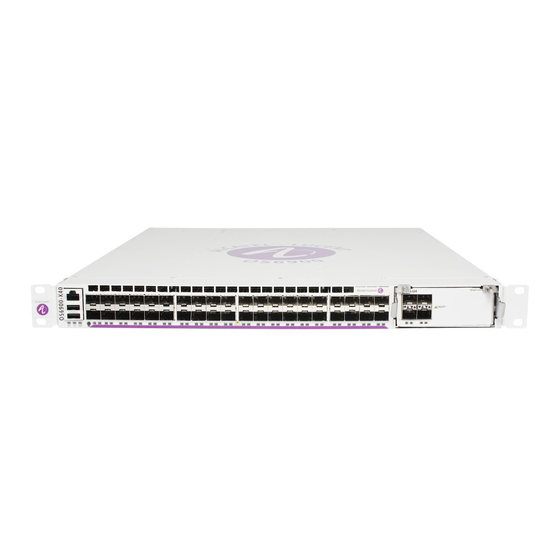
1 OmniSwitch 6860 Refer to the information below for OmniSwitch 6860 (OS6860) models and components. Model Number Description OS6860-24 Fixed-configuration chassis in a 1U form factor with 24 10/100/1000 Base-T ports, four fixed SFP+ (1G/10G) ports and two 20G Virtual Chassis link ports. - Page 16 150W power supply.) All models include one console connector (for use with Micro USB-to-USB cable, included); one USB connector (for use with Alcatel-Lucent flash drive or Bluetooth dongle, not included); and one RS-232 connector.
-
Page 17: Omniswitch 6860 Availability Features
The following hardware components can be hot-swapped: Power supplies • Transceivers • Plug-in modules • Note. For information on adding and removing power supplies and plug-in modules, refer to Chapter 3, “Chassis and Power Supplies.” OmniSwitch 6860 Hardware Users Guide May 2017 page 1-3... -
Page 18: Hardware Monitoring
The user enters “show” commands that output information to the console. The show commands for all the features are described in detail in the OmniSwitch CLI Reference Guide. page 1-4 OmniSwitch 6860 Hardware Users Guide May 2017... -
Page 19: Chapter 2 Getting Started
Electrical Requirements Note. Alcatel-Lucent switches must be installed by a professional installer. It is the responsibility of the installer to ensure that proper grounding is available and that the installation meets applicable local and national electrical codes. -
Page 20: Electrical Surge Warning
Ethernet cables (especially in new cable runs) to a suitable and safe earth ground before connect- ing them to the port. Note. Failure to follow the above recommendations could result in voiding the warranty of the affected ALE product. page 2-2 OmniSwitch 6860 Hardware Users Guide May 2017... -
Page 21: Unpacking And Installing The Switch
To protect your switch components from damage, read all unpacking recommendations and instructions carefully before beginning. Unpack your OmniSwitch 6860 chassis as close as possible to the location where it will be installed. Items Included Your OmniSwitch 6860 includes the following items: OmniSwitch chassis with power supplies, per order •... -
Page 22: Airflow Considerations
Chassis Top View Note. Clearance is not required at the top and bottom of the chassis. Mounting the Switch For information on mounting OmniSwitch 6860 switches, refer to the Chapter 3, “Chassis and Power Supplies.” page 2-4... -
Page 23: Connections And Cabling
EMP is connecting. Refer to the information below: EMP to a Switch Straight-through EMP to a Computer or Crossover Workstation For information on manually configuring Ethernet ports, refer to the OmniSwitch AOS Release 8 Network Configuration Guide. OmniSwitch 6860 Hardware Users Guide May 2017 page 2-5... -
Page 24: Booting The Switch
If the LEDs do not display as indicated, make sure the boot process is complete. If the LEDs do not display as indicated following a complete boot sequence, contact Alcatel-Lucent Customer Support. For complete information on LED states, refer to “Chassis Status LEDs”... -
Page 25: Your First Login Session
Welcome to the Alcatel-Lucent OS6860E-P48 8.1.1, April 15, 2014. Copyright (c) 1994-2014 Alcatel-Lucent. All Rights Reserved. OmniSwitch(tm) is a trademark of Alcatel-Lucent, registered in the United States Patent and Trademark Office. -> Note. A user account includes a login name, password, and user privileges. Privileges determine whether the user has read or write access to the switch and which commands the user is authorized to execute. -
Page 26: Setting Ip Address Information For The Emp
(i.e. TELNET, FTP, HTTP, SSH or SNMP) until you have unlocked these remote session types. See “Unlocking Session Types” on page 2-9 for more information. page 2-8 OmniSwitch 6860 Hardware Users Guide May 2017... -
Page 27: Unlocking Session Types
Getting Started Your First Login Session Unlocking Session Types Security is a key feature on OmniSwitch 6860 switches. As described on page 2-7, when you access the switch for the first time, you must use a direct console port connection. All other session types (Telnet, FTP, WebView, and SNMP) are locked out until they are manually unlocked by the user. -
Page 28: Setting The System Time Zone
However, if no labeling system has been implemented or if you need to determine a switch’s location from a remote site, entering a system location can be very useful. To specify a system location, use the system location command. page 2-10 OmniSwitch 6860 Hardware Users Guide May 2017... -
Page 29: Viewing Your Changes
To view your current changes, enter show system at the CLI prompt. Saving Your Changes Once you have configured this basic switch information, save your changes by entering write memory at the CLI command prompt. OmniSwitch 6860 Hardware Users Guide May 2017 page 2-11... - Page 30 Your First Login Session Getting Started page 2-12 OmniSwitch 6860 Hardware Users Guide May 2017...
-
Page 31: Chassis And Power Supplies
3 Chassis and Power Supplies This chapter includes detailed information on the OmniSwitch 6860 switch. Topics include: Chassis details and technical specifications: • Basic Models - Non-PoE OS6860-24, page 3-2. OS6860-48, page 3-4. Basic Models - PoE OS6860-P24, page 3-6. -
Page 32: Omniswitch 6860 Chassis Details
DO NOT VIEW DIRECTLY WITH OPTICAL INSTRUMENTS OS6860-24 Rear Panel PS 2 PS 1 Item Description Chassis Grounding Lug OmniSwitch Backup Power Supply (OS-BPS) (No longer supported.) Power Supply/Fan Tray Bays page 3-2 OmniSwitch 6860 Hardware Users Guide May 2017... -
Page 33: Os6860-24 Chassis Specifications
*Note On Chassis Versus Ambient Temperatures. Chassis temperature refers to the sensor reading of the internal switch temperature (threshold or danger). Ambient temperature refers to the approximate room temperature. The ambient temperature will typically be lower than the chassis temperature. OmniSwitch 6860 Hardware Users Guide May 2017 page 3-3... -
Page 34: Omniswitch 6860-48
DO NOT VIEW DIRECTLY WITH OPTICAL INSTRUMENTS OS6860-48 Rear Panel PS 2 PS 1 Item Description Chassis Grounding Lug OmniSwitch Backup Power Supply (OS-BPS) (No longer supported.) Power Supply/Fan Tray Bays page 3-4 OmniSwitch 6860 Hardware Users Guide May 2017... -
Page 35: Os6860-48 Chassis Specifications
*Note On Chassis Versus Ambient Temperatures. Chassis temperature refers to the sensor reading of the internal switch temperature (threshold or danger). Ambient temperature refers to the approximate room temperature. The ambient temperature will typically be lower than the chassis temperature. OmniSwitch 6860 Hardware Users Guide May 2017 page 3-5... -
Page 36: Omniswitch 6860-P24
CLASS 1 M LASER CAUTION. CAUTION - CLASS 1 M LASER RADIATION WHEN OPEN. DO NOT VIEW DIRECTLY WITH OPTICAL INSTRUMENTS OS6860-P24 Rear Panel Item Description Chassis Grounding Lug Fan Vent OmniSwitch Backup Power Supply (OS-BPS) (No longer supported.) PoE Power Supply Bays page 3-6 OmniSwitch 6860 Hardware Users Guide May 2017... -
Page 37: Os6860-P24 Chassis Specifications
*Note On Chassis Versus Ambient Temperatures. Chassis temperature refers to the sensor reading of the internal switch temperature (threshold or danger). Ambient temperature refers to the approximate room temperature. The ambient temperature will typically be lower than the chassis temperature. OmniSwitch 6860 Hardware Users Guide May 2017 page 3-7... -
Page 38: Omniswitch 6860-P48
CLASS 1 M LASER CAUTION. CAUTION - CLASS 1 M LASER RADIATION WHEN OPEN. DO NOT VIEW DIRECTLY WITH OPTICAL INSTRUMENTS OS6860-P48 Rear Panel Item Description Chassis Grounding Lug Fan Vent OmniSwitch Backup Power Supply (OS-BPS) (No longer supported.) PoE Power Supply Bays page 3-8 OmniSwitch 6860 Hardware Users Guide May 2017... -
Page 39: Os6860-P48 Chassis Specifications
*Note On Chassis Versus Ambient Temperatures. Chassis temperature refers to the sensor reading of the internal switch temperature (threshold or danger). Ambient temperature refers to the approximate room temperature. The ambient temperature will typically be lower than the chassis temperature. OmniSwitch 6860 Hardware Users Guide May 2017 page 3-9... -
Page 40: Omniswitch 6860E-24
OS6860E-24 Rear Panel EM P PS 2 PS 1 Item Description Chassis Grounding Lug Ethernet Management Port (EMP) for Out-of-Band Management OmniSwitch Backup Power Supply (OS-BPS) (No longer supported.) Power Supply/Fan Tray Bays page 3-10 OmniSwitch 6860 Hardware Users Guide May 2017... -
Page 41: Os6860E-24 Chassis Specifications
*Note On Chassis Versus Ambient Temperatures. Chassis temperature refers to the sensor reading of the internal switch temperature (threshold or danger). Ambient temperature refers to the approximate room temperature. The ambient temperature will typically be lower than the chassis temperature. OmniSwitch 6860 Hardware Users Guide May 2017 page 3-11... -
Page 42: Omniswitch 6860E-48
OS6860E-48 Rear Panel EM P PS 2 PS 1 Item Description Chassis Grounding Lug Ethernet Management Port (EMP) for Out-of-Band Management OmniSwitch Backup Power Supply (OS-BPS) (No longer supported.) Power Supply/Fan Tray Bays page 3-12 OmniSwitch 6860 Hardware Users Guide May 2017... -
Page 43: Os6860E-48 Chassis Specifications
*Note On Chassis Versus Ambient Temperatures. Chassis temperature refers to the sensor reading of the internal switch temperature (threshold or danger). Ambient temperature refers to the approximate room temperature. The ambient temperature will typically be lower than the chassis temperature. OmniSwitch 6860 Hardware Users Guide May 2017 page 3-13... -
Page 44: Omniswitch 6860E-U28
OS6860E-U28 Rear Panel EM P PS 2 PS 1 Item Description Chassis Grounding Lug Ethernet Management Port (EMP) for Out-of-Band Management OmniSwitch Backup Power Supply (OS-BPS) (No longer supported.) Power Supply/Fan Tray Bays page 3-14 OmniSwitch 6860 Hardware Users Guide May 2017... -
Page 45: Os6860E-U28 Chassis Specifications
*Note On Chassis Versus Ambient Temperatures. Chassis temperature refers to the sensor reading of the internal switch temperature (threshold or danger). Ambient temperature refers to the approximate room temperature. The ambient temperature will typically be lower than the chassis temperature. OmniSwitch 6860 Hardware Users Guide May 2017 page 3-15... -
Page 46: Omniswitch 6860E-P24
DO NOT VIEW DIRECTLY WITH OPTICAL INSTRUMENTS OS6860E-P24 Rear Panel Item Description Chassis Grounding Lug Ethernet Management Port (EMP) for Out-of-Band Management Fan Vent OmniSwitch Backup Power Supply (OS-BPS) (No longer supported.) Power Supply Bays page 3-16 OmniSwitch 6860 Hardware Users Guide May 2017... -
Page 47: Os6860E-P24 Chassis Specifications
*Note On Chassis Versus Ambient Temperatures. Chassis temperature refers to the sensor reading of the internal switch temperature (threshold or danger). Ambient temperature refers to the approximate room temperature. The ambient temperature will typically be lower than the chassis temperature. OmniSwitch 6860 Hardware Users Guide May 2017 page 3-17... -
Page 48: Omniswitch 6860E-P48
DO NOT VIEW DIRECTLY WITH OPTICAL INSTRUMENTS OS6860E-P48 Rear Panel Item Description Chassis Grounding Lug Ethernet Management Port (EMP) for Out-of-Band Management Fan Vent OmniSwitch Backup Power Supply (OS-BPS) (No longer supported.) Power Supply Bays page 3-18 OmniSwitch 6860 Hardware Users Guide May 2017... -
Page 49: Os6860E-P48 Chassis Specifications
*Note On Chassis Versus Ambient Temperatures. Chassis temperature refers to the sensor reading of the internal switch temperature (threshold or danger). Ambient temperature refers to the approximate room temperature. The ambient temperature will typically be lower than the chassis temperature. OmniSwitch 6860 Hardware Users Guide May 2017 page 3-19... -
Page 50: Omniswitch 6860E-P24Z8
CAUTION - CLASS 1 M LASER RADIATION WHEN OPEN. DO NOT VIEW DIRECTLY WITH OPTICAL INSTRUMENTS OS6860E-P24Z8 Rear Panel OmniSwitch 6860E-P24Z8 Rear Panel Chassis Grounding Lug Ethernet Management Port (EMP) for Out-of-Band Management Fan Vent Power Supply Bays page 3-20 OmniSwitch 6860 Hardware Users Guide May 2017... -
Page 51: Os6860E-P24Z8 Chassis Specifications
System Diagnostics and/or AOS bootup failed Solid Green This unit is the master unit Solid Amber This unit is a slave unit This unit is in shutdown mode or is not part of a VC. OmniSwitch 6860 Hardware Users Guide May 2017 page 3-21... - Page 52 2.5G valid port link with activity (non-PoE) Solid Blue+Yellow 2.5G valid port link (PoE) Blinking Blue+Yellow 2.5G valid port link with activity (PoE) Note: The blue LED may flash at a reduced frequency for the 2.5G ports. page 3-22 OmniSwitch 6860 Hardware Users Guide May 2017...
-
Page 53: Mounting The Switch
Reliable Earthing. Reliable earthing of rack-mounted equipment should be maintained. Particular attention should be given to supply connections other than direct connections to the branch (e.g., use of power strips). OmniSwitch 6860 Hardware Users Guide May 2017 page 3-23... -
Page 54: Airflow Recommendations
Sides. 2 inches minimum at left and right sides. Front. 6 inches minimum at front of chassis. Chassis Top View Note. Clearance is not required at the top and bottom of the chassis. page 3-24 OmniSwitch 6860 Hardware Users Guide May 2017... -
Page 55: Blank Cover Panels
When installing blank cover panels over power supply slots, orient the cover panels with the arrows pointing up. Face arrow up when installing. Insert the blank cover panel in the empty chassis slot and secure using attachment screws (provided). OmniSwitch 6860 Hardware Users Guide May 2017 page 3-25... -
Page 56: Rack-Mounting
The chassis has rack-mount flanges that support standard 19-inch rack mount installations. • Alcatel-Lucent Enterprise does not provide rack-mount screws. Use the screws supplied by the • rack vendor. - Page 57 Clip in “In” (engaged) position “CLICK” Secure the flange to the chassis using the attachment screw (provided). Repeat steps 1 through 4 for the flange on the opposite side of the chassis. OmniSwitch 6860 Hardware Users Guide May 2017 page 3-27...
-
Page 58: Installing The Chassis In The Rack
Once the holes are aligned, the second person should insert a screw through the bottom hole on each flange. Tighten both screws until they are secure. Install the remaining screws in the top hole of each flange. Be sure that all screws are securely tightened. page 3-28 OmniSwitch 6860 Hardware Users Guide May 2017... -
Page 59: Standalone (Non-Rack Mounted) Installations
Place the switch on the tabletop “right side up.” Note. Never attempt to operate a switch while it is placed on its top or side. Connect network and management cables as needed. OmniSwitch 6860 Hardware Users Guide May 2017 page 3-29... -
Page 60: Power Supplies
OS6860-BP-PX 920W AC OS6860-P48, OS6860E-P48, OS6860E-P24Z8 PoE PSU OmniSwitch 6860 power supplies are located at the rear of the switch chassis. Refer to “OmniSwitch 6860 Chassis Details” for more information on component locations. Two slots are provided. If a second power supply is installed, it will assume a standby role. -
Page 61: Dying Gasp
Use the swlog output socket command to add a Syslog station. Refer to the Using Switch Logging Configuration chapter in the Network Configuration Guide for information on configuring a Syslog server. OmniSwitch 6860 Hardware Users Guide May 2017 page 3-31... -
Page 62: Os6860-Bp 150W Power Supply
Flashing Green/Red Power supply warning Solid Red Power supply failure No AC power is being provided to any power supply installed in the chassis; all power supplies are effectively off page 3-32 OmniSwitch 6860 Hardware Users Guide May 2017... -
Page 63: Os6860-Bp-D 150W Dc Power Supply
Flashing Green/Red Power supply warning Solid Red Power supply failure No power is being provided to any power supply installed in the chassis; all power supplies are effectively off OmniSwitch 6860 Hardware Users Guide May 2017 page 3-33... -
Page 64: Os6860-Bp-Ph 600W Power Supply
AC OK LED Solid Red There is an AC power issue DC OK LED Solid Green DC power is good DC OK LED Solid Red There is a DC power issue page 3-34 OmniSwitch 6860 Hardware Users Guide May 2017... -
Page 65: Os6860-Bp-Px 920W Power Supply
AC OK LED Solid Red There is an AC power issue DC OK LED Solid Green DC power is good DC OK LED Solid Red There is a DC power issue OmniSwitch 6860 Hardware Users Guide May 2017 page 3-35... -
Page 66: Dc Power Supply Connections
Observe proper polarity when connecting to a fuse panel. The cable wire leads must be connected as follows: Green/yellow - ground • Black - return • Red - -48VDC • Note. The battery return conductor is an Isolated DC Return (DC-1). page 3-36 OmniSwitch 6860 Hardware Users Guide May 2017... -
Page 67: Installing Power Supplies
Insert the power supply into a power supply bay at the rear of the chassis and slide it back until it is securely seated in the chassis backplane. When the connector is fully seated, the lock tab will click and hold the power supply in place. Lock Tab OmniSwitch 6860 Hardware Users Guide May 2017 page 3-37... - Page 68 Plug the power cord (provided) into the power supply’s socket. Note. The chassis does not provide an on/off switch. Connecting a the power supplies to a power source will boot the switch. page 3-38 OmniSwitch 6860 Hardware Users Guide May 2017...
-
Page 69: Removing Power Supplies
Pressing the lock tab toward the center of the power supply, as shown, will free the power supply from the chassis. Lock Tab OmniSwitch 6860 Hardware Users Guide May 2017 page 3-39... - Page 70 While pressing the lock tab, pull the power supply straight back and out of the chassis slot. Note. If you are not replacing the power supply, be sure to install a blank cover panel over the empty power supply bay. page 3-40 OmniSwitch 6860 Hardware Users Guide May 2017...
-
Page 71: Grounding The Chassis
Use this connector to supplement the ground provided by the AC power cord. To do so, install a Panduit Grounding Lug (type LCD8-10A-L) using 8AWG copper conductors to the paint-free area. Refer to the rear chassis views on page 3-2 for location details. OmniSwitch 6860 Hardware Users Guide May 2017 page 3-41... -
Page 72: Os6860 Fantray Nonpoe Fan Tray
OS6860-24, OS6860E-24, OS6860-48, OS6860E-48, OS6860E-U28 OS6860 FANTRAY NONPOE LED States LED State Description Solid Green Fan tray is receiving power and operating normally The fan tray is off or a failure has occurred page 3-42 OmniSwitch 6860 Hardware Users Guide May 2017... -
Page 73: Monitoring Chassis Components
15-93 UNDER THRESHOLD 2/CMMA 15-85 UNDER THRESHOLD 2/Slot1 15-85 UNDER THRESHOLD For more information about this command, see the “Chassis Management and Monitoring Commands” chapter in the OmniSwitch CLI Reference Guide. OmniSwitch 6860 Hardware Users Guide May 2017 page 3-43... -
Page 74: Temperature Errors
The danger threshold is factory-set and cannot be configured by the user. Addressing danger threshold temperature conditions may include: Checking for a chassis airflow obstruction • Checking the ambient room temperature • page 3-44 OmniSwitch 6860 Hardware Users Guide May 2017... -
Page 75: Managing Power Over Ethernet (Poe)
As the switches fully support 10/100/1000 Ethernet connectivity, you may also attach non-PD equipment, such as computer workstations, printers, servers, etc. to the PoE ports. Important. Alcatel-Lucent recommends that PoE-enabled switches with attached IP telephones should have operational power supply redundancy at all times for 911 emergency requirements. In addition, both the switch and the power supply should be plugged into an Uninterruptible Power Source (UPS). -
Page 76: In This Chapter
Note. You can also monitor all chassis components and manage many chassis features, including Power over Ethernet, with WebView, Alcatel-Lucent’s embedded web-based device management application. WebView is an interactive and easy-to-use GUI that can be launched from the OmniVista or a web browser. -
Page 77: Power Over Ethernet Specifications
Viewing Power Supply Status To view the type and status for installed power supplies, use the show powersupply command: -> show powersupply Total Chassis/PS Power Type Status Location -----------+---------+--------+--------+----------- Internal Total OmniSwitch 6860 Hardware Users Guide May 2017 page 4-3... -
Page 78: Viewing Poe Status
Power available to an entire slot lanpower slot maxpower 920W power supply- 780W 600W power supply - 450W Power priority level for a port lanpower priority Capacitor detection method lanpower capacitor-detection Disabled page 4-4 OmniSwitch 6860 Hardware Users Guide May 2017... -
Page 79: Understanding And Modifying The Default Settings
PDs will receive inline power. To activate power to PoE-capable in a switch, enter the corresponding slot number only. For example: -> lanpower slot 2/1 service start OmniSwitch 6860 Hardware Users Guide May 2017 page 4-5... -
Page 80: Configuring The Total Power Available To A Port
As with the maximum port power allowance, the user can either increase or decrease this value based on the allowed ranges. Important. Decreasing the slot-wide power could cause lower priority ports to lose power if the new value is less than the total PoE power currently being consumed. page 4-6 OmniSwitch 6860 Hardware Users Guide May 2017... -
Page 81: Setting Port Priority Levels
Note. The capacitive detection method should only be enabled to support legacy IP phones. This feature is not compatible with IEEE specifications. Please contact your Alcatel-Lucent sales engineer or Customer Support representative to find out which Alcatel-Lucent IP phones models need capacitive detection enabled. -
Page 82: Understanding Priority Disconnect
For example: -> lanpower slot 2/1 priority-disconnect disable Enabling Priority Disconnect To enable priority disconnect, use the lanpower slot priority-disconnect command. For example: -> lanpower slot 2/1 priority-disconnect enable page 4-8 OmniSwitch 6860 Hardware Users Guide May 2017... -
Page 83: Priority Disconnect Is Enabled; Same Priority Level On All Pd
When a PD is being connected to a port with a lower priority level than all other in the slot, the incoming PD will be denied power, regardless of its physical port number. Devices connected to other higher-prior- ity will continue operating without interruption. OmniSwitch 6860 Hardware Users Guide May 2017 page 4-9... -
Page 84: Priority Disconnect Is Disabled
PDs in the case of the power budget being reduced, such as the removal of a power supply. Please refer to the “Understanding Priority Disconnect” on page 4-8 for additional details. page 4-10 OmniSwitch 6860 Hardware Users Guide May 2017... -
Page 85: Monitoring Power Over Ethernet Via Cli
Undefined 30000 Undefined 30000 Undefined Slot 3 Max Watts 150 1 Power Supplies Available Note. For detailed information on show lanpower command output, refer to the OmniSwitch CLI Refer- ence Guide. OmniSwitch 6860 Hardware Users Guide May 2017 page 4-11... - Page 86 Monitoring Power over Ethernet via CLI Managing Power over Ethernet (PoE) page 4-12 OmniSwitch 6860 Hardware Users Guide May 2017...
-
Page 87: Regulatory Compliance And Safety Information
A Regulatory Compliance and Safety Information This appendix provides information on regulatory agency compliance and safety for OmniSwitch 6860 switches. Declaration of Conformity: CE Mark This equipment is in compliance with the essential requirements and other provisions of Directive 2004/108/EC (EMC), 2006/95/EC (LVD), 91/263/EEC (Telecom Terminal Equipment, if applicable), 1999/5/EC (R&TTE, if applicable). -
Page 88: China Rohs: Hazardous Substance Table
WARNING: This product contains chemicals known to the State of California to cause cancer and birth defects or other reproductive harm. Products are packaged using one or more of the following packaging materials: Corrugated Cardboard Corrugated Fiberboard Low-Density Polyethylene page A-2 OmniSwitch 6860 Hardware Users Guide May 2017... -
Page 89: Standards Compliance
The product bears the CE mark. In addition it is in compliance with the following other safety and EMC standards. Note. All hardware switching modules used in an OmniSwitch 6860 switch comply with Class A standards. Modules with copper connectors meet Class A requirements using unshielded (UTP) cables. - Page 90 (2250 V DC on all Ethernet ports) Environmental Standards ETS 300 019 Storage Class 1.1 • ETS 300 019 Transportation Class 2.3 • ETS 300 019 Stationary Use Class 3.1 • page A-4 OmniSwitch 6860 Hardware Users Guide May 2017...
-
Page 91: Fcc Class A, Part 15
CISPR22 Class A warning This is a Class A product. In a domestic environment, this product may cause radio interference. Under such circumstances, the user may be requested to take appropriate countermeasures. OmniSwitch 6860 Hardware Users Guide May 2017 page A-5... -
Page 92: Korea Emissions Statement
Class 1M Laser Warning CLASS 1M LASER RADIATION WHEN OPEN. DO NOT VIEW DIRECTLY WITH OPTICAL INSTRUMENTS. Network Cable Installation Warning Never install exposed network cables outdoors. Install network cables per manufacturer requirements. page A-6 OmniSwitch 6860 Hardware Users Guide May 2017... -
Page 93: Translated Safety Warnings
Deutsch: Dieses Gerät soll nur von Personal installiert oder gewartet werden, welches in elektrischen und mechanischen Grundlagen ausgebildet ist. Español: Estos equipos deben ser instalados y atendidos exclusivamente por personal adecuadamente formado y capacitado en técnicas eléctricas y mecánicas. OmniSwitch 6860 Hardware Users Guide May 2017 page A-7... -
Page 94: Invisible Laser Radiation Warning
Netzverbindungen getrennt sind bevor das Gerät gewartet oder bewegt wird. Español: Antes de empezar a trabajar con un sistema, asegurese que el interruptor está cerrado y el cable eléctrico desconectado. page A-8 OmniSwitch 6860 Hardware Users Guide May 2017... -
Page 95: Proper Earthing Requirement Warning
Erde angeschlossen werden. Español: Para EMC/EMI, cada fuente de alimentación de CC/CC requiere que el cable de tierra esté conectado desde cada fuente de alimentación de CC/CC a la conexión a tierra común. OmniSwitch 6860 Hardware Users Guide May 2017 page A-9... -
Page 96: Read Important Safety Information Warning
Español: Debido a las descargas electrostáticas (ESD) puede dañar los componentes del interruptor, debe seguir los procedimientos adecuados para eliminar la EDS de su persona y sus alrededores antes de manipular los componentes del interruptor. page A-10 OmniSwitch 6860 Hardware Users Guide May 2017... -
Page 97: Instrucciones De Seguridad En Español
Deseche las baterías usadas según las instrucciones del fabricante. Las instrucciones del fabricante son como sigue: Devuelva el módulo con la batería del litio a Alcatel-Lucent. La batería del litio será substituida en la fábrica de Alcatel-Lucent. -
Page 98: Advertencia Sobre Una Apropiada Conexión A Tierra
Para este propósito, Alcatel-Lucent proporciona una pulsera antiestática y un terminal que pone a tierra situados cerca de la parte superior derecha del chasis. Para que la pulsera antiestática sea eficaz en la eliminación de ESD, las fuentes de alimentación se deben instalar en el chasis y enchufar en las salidas de CA con descarga a...
Need help?
Do you have a question about the OmniSwitch 6860 and is the answer not in the manual?
Questions and answers