Getac V100 User Manual
Hide thumbs
Also See for V100:
- User manual (187 pages) ,
- Operation manual (111 pages) ,
- Quick start manual (2 pages)
Table of Contents
Advertisement
Quick Links
Advertisement
Table of Contents

Related Manuals for Getac V100


Summary of Contents for Getac V100
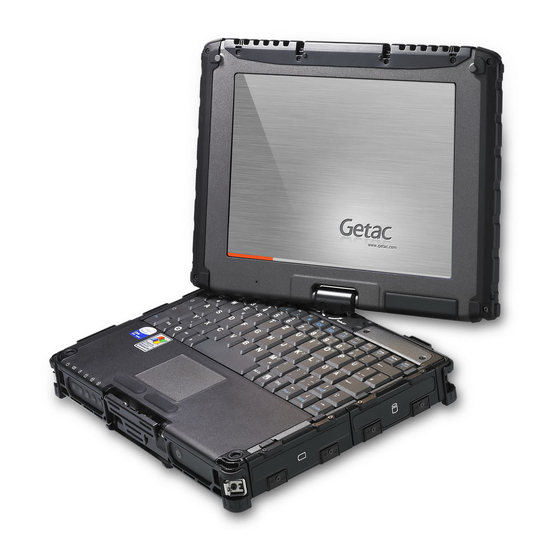
- Page 1 V100 USER’S MANUAL Rugged Mobile Computing Solutions...
- Page 2 All brand and product names are trademarks or registered trademarks of their respective companies. NOTE The information in this manual is subject to change without notice. For the latest version of the manual, please visit the Getac website at www.getac.com.
-
Page 3: Table Of Contents
Table of Contents Chapter 1 Getting Started ............. 1-1 Getting the Computer Running ..........1-2 Unpacking ................1-2 Connecting to AC Power ............ 1-3 Opening and Closing the Cover ........1-4 Operating in Tablet Mode ..........1-6 Turning On and Off the Computer ........1-8 Taking a Look at the Computer .......... - Page 4 Fn Key .................. 2-4 Hot Keys ................2-4 Using the Touchpad ..............2-6 Configuring the Touchpad ..........2-8 Navigating on the Screen ............2-9 Using the Touchscreen ............2-9 Using Multi-touch Gestures ..........2-10 Using the Dual Mode Display (Optional) ......2-12 Using Landscape or Portrait View ........
- Page 5 Boot Menu ................ 5-13 Exit Menu ................5-14 System Recovery ..............5-15 Chapter 6 Using Getac Software ........... 6-1 Using the OSD Control Panel ..........6-2 Quick Button Setup ............6-6 Using Button Manager ............6-8 Using G-Manager ..............6-10 Starting G-Manager ............
- Page 6 Ignition Tab ............... 6-18 Monitoring Tab ..............6-19 GPS Status Tab ..............6-21 Using Getac Camera .............. 6-22 Taking Pictures ..............6-24 Shooting Videos ..............6-26 Using View Mode ............. 6-27 Camera Settings ..............6-31 Chapter 7 Caring for the Computer ..........7-1 Protecting the Computer ............
- Page 7 Startup Problems ..............8-8 WLAN Problems ..............8-9 Other Problems ..............8-11 Resetting the Computer ............8-12 Appendix A Specifications ............... A-1 Appendix B Regulatory Information ..........B-1 On the Use of the System ............B-2 Class B Regulations ............. B-2 Safety Notices ..............
-
Page 9: Chapter 1 Getting Started
Chapter 1 Getting Started Congratulations on purchasing this rugged computer. This chapter first tells you step by step how to get the computer up and running. Then, you will find a section briefly introducing the external components of the computer. Getting Started... -
Page 10: Getting The Computer Running
Getting the Computer Running This section guides you through the procedures for getting the computer ready for operation. Unpacking After unpacking the shipping carton, you should find these standard items: Notebook computer Accessories: − AC adapter − AC power cord −... -
Page 11: Connecting To Ac Power
Connecting to AC Power The computer operates either on the external AC power or internal battery power. It is suggested that you use AC power when you start up the computer for the very first time. CAUTION: Use only the AC adapter included with your computer. Using other AC adapters may damage the computer. -
Page 12: Opening And Closing The Cover
NOTE: When the AC adapter is connected, it also charges the battery pack. For information on using battery power, see Chapter 3. Opening and Closing the Cover Open the top cover by pulling up on latch A and releasing latch B ( ) and ... - Page 13 Close the top cover by closing the display (). Then position latch B on the display side and bring latch A down () to fix the display in place. Latch B Latch A Getting Started...
-
Page 14: Operating In Tablet Mode
Operating in Tablet Mode In addition to being used as a regular notebook computer (Laptop mode), your computer can also be operated in Tablet mode. In Tablet mode, you operate the computer with a stylus or digitizer pen, or a fingertip, instead of a keyboard or mouse. - Page 15 4. Position the latch B on the display side, then bring latch A down () to fix the display in place. Latch B Latch A In Tablet mode, the computer can be operated while holding it as shown. A handgrip strap is supplied to help you hold the computer. (See “Attaching the Handgrip Strap”...
-
Page 16: Turning On And Off The Computer
Turning On and Off the Computer Turning On Press the power button ( ). Each time the computer is turned on, it performs a Power-On Self Test (POST), and the operating system such as Windows should start. Turning Off When you finish a working session, you can stop the system by turning off the power or leaving it in Sleep or Hibernation mode: To... -
Page 17: Taking A Look At The Computer
Taking a Look at the Computer NOTE: Depending on the model you purchased, the appearance of your computer may not be exactly the same as those shown in this manual. CAUTION: You need to open the protective covers to access the connectors or devices inside. - Page 18 Component Description See Also CAUTION: To prevent burns to your fingers if using the computer (especially in Tablet Mode) with sunlight-readable mode turned on, do wear gloves when touching the top portion of the LCD display as it may be hot to the touch.
-
Page 19: Rear Components
Rear Components Component Description See Also Mini IEEE 1394 Connects an IEEE 1394 device such as a P. 4-5 Port scanner, printer, DVCAM, and VCR. Audio Output Connects a set of headphones, external P. 4-6 Connector speakers with amplifier, or an audio recording device. -
Page 20: Right-Side Components
Right-Side Components Component Description See Also Stylus Serves as the input device by tapping on the P. 2-9 touchscreen to make selections and enter information. NOTE: Some models do not have the stylus slot on the right side, so you can only use the slot on the left side for storing the stylus. -
Page 21: Left-Side Components
Left-Side Components Component Description See Also Tether Hole Stylus can be tethered to this hole. P. 1-16 Stylus Slot Stylus can be stored in this slot. Power Connects the AC adapter. P. 1-3 Connector USB Port Connects a USB device, such as a flash disk, P. -
Page 22: Top-Open Components
Component Description See Also SD Card Reader Accepts an SD/SDHC/SDXC card for P. 4-12 removable storage media. Top-open Components Component Description See Also Camera Lens Allows you to use your computer’s camera P. 6-22 function. The lens supports 2 MP (mega pixel). - Page 23 Component Description See Also Light Sensor Detects the surrounding lighting condition for automatic adjustment of the LCD brightness and optional keyboard backlight. Fingerprint Uses fingerprint verification to protect your P. 2-26 Scanner computer against unauthorized access. (optional) Keyboard Serves as the data input device.
-
Page 24: Bottom Components
Bottom Components Component Description See Also Strap Holder Four bottom hooks hold the handgrip strap. P. 1-18 Docking Inside is the docking connector for Connector connecting an office dock or vehicle dock (purchased separately). Memory Slots Inside are the memory slots for expanding P. -
Page 25: Using Accessories
Using Accessories Using the Tether A tether is provided for attaching the stylus to your computer. 1. Insert one of the tether’s loop ends through the hole of the stylus (as indicated by below). Then, insert the other end through the first loop ... -
Page 26: Attaching The Handgrip Strap
Attaching the Handgrip Strap To use the handgrip strap, attach its four loops to the four bottom hooks on your computer. Make sure the loops are securely hooked. When you need to operate and hold your computer at the same time, insert your hand through the strap for a firm grip. - Page 27 CAUTION: The strap has been designed to carry only the weight of the computer. Therefore, be sure that the strap does not carry a weight that exceeds the weight of the computer. The strap may accidentally come loose from the computer. Do not use a strap that is damaged or about to tear.
-
Page 29: Operating Your Computer
Chapter 2 Operating Your Computer This chapter provides information about the use of the computer. If you are new to computers, reading this chapter will help you learn the operating basics. If you are already a computer user, you may choose to read only the parts containing information unique to your computer. -
Page 30: Using The Internal Keyboard
Using the Internal Keyboard Your keyboard has all the standard functions of a full-sized computer keyboard plus an Fn key added for specific functions. The standard functions of the keyboard can be further divided into four major categories: Typewriter keys ... -
Page 31: Numeric Keypad
Numeric Keypad A 15-key numeric keypad is embedded in the typewriter keys as shown next: Numeric keys facilitate entering of numbers and calculations. When Num Lock is on, the numeric keys are activated; meaning you can use these keys to enter numerals. NOTE: When the numeric keypad is activated and you need to type the English ... -
Page 32: Function Keys
Function Keys On the top row of the keys are the function keys: F1 to F12. Function keys are multi-purpose keys that perform functions defined by individual programs. Fn Key The Fn key, at the lower left corner of the keyboard, is used with another key to perform the alternative function of a key. -
Page 33: Windows Keys
Description Decreases the LCD brightness (20 levels). Increases the LCD brightness (20 levels). Switches the system sound output off (mute) and on. Switches LCD backlight on and off. Switches the display output when external devices are connected. Serves as the sleep button that you can define with Windows’... -
Page 34: Using The Touchpad
Using the Touchpad CAUTION: Do not use a sharp object such as a pen on the touchpad. Doing so may damage the touchpad surface. NOTE: For optimal performance of the touchpad, keep your fingers and the pads clean and dry. When tapping on the pad, tap lightly. Do not use excessive force. - Page 35 Term Action Point Move your finger on the pad until the cursor points to the selection on the screen. Click Press and release the left button. –or– Tap gently anywhere on the pad. Double-click Press and release the left button twice in quick succession. –or–...
-
Page 36: Configuring The Touchpad
Configuring the Touchpad You may want to configure the touchpad to suit your needs. For example, if you are a left-handed user, you can swap the two buttons so that you can use the right button as the left button and vice versa. You can also change the size of the on-screen pointer, the speed of the pointer, and so on. -
Page 37: Navigating On The Screen
Navigating on the Screen The screen of your computer is touch-sensitive. You can control the location of the cursor/pointer on the screen using your finger or the included stylus or digitizer pen to communicate with the computer. CAUTION: Do not use sharp objects on the LCD display. Doing so may damage the display surface. -
Page 38: Using Multi-Touch Gestures
Equivalent Term/Action Mouse Function Tap and hold: Tap and hold until a popup menu Right-click appears. Drag: Hold the stylus (or finger) on the screen and Drag drag across the screen until reaching your destination. Using Multi-touch Gestures If your computer model comes with multi-touch-capable screen and Windows 7, you can interact with your computer by placing two fingers on the screen. - Page 39 Actions Gestures Descriptions = finger down; = finger up) Rotate Use rotating to move a picture or other item on the screen in a circular direction (clockwise or counter- clockwise). The gesture Move two fingers in opposing works in applications directions.
-
Page 40: Using The Dual Mode Display (Optional)
Actions Gestures Descriptions = finger down; = finger up) Flicks Flick left or right to navigate back and forward in a browser and other applications. The gesture works in most applications that Make quick drag gestures in the support back and desired direction. - Page 41 Term Action Move Move the cursor pointed by the digitizer pen. Click/Point Tap gently on the display. Double-click Tap twice on the display rapidly. Drag and Tap lightly on the display and move your drop digitizer pen until you reach your destination (drag).
-
Page 42: Using Landscape Or Portrait View
The active digitizer feature cannot be used in the BIOS Setup program or when using the full screen in DOS mode. NOTE: You can move the cursor by bringing the digitizer pen close to the screen, without actually touching the screen’s surface. Do not move the digitizer pen too quickly. - Page 43 For a Model with WWAN Module Primary Secondary Primary Landscape Landscape Landscape Display Display Display NOTE: If the screen display resolution has been set to 800×600 pixels, you can rotate the display to Primary Landscape and Secondary Landscape only. While the display is rotated: ...
-
Page 44: Using The Input Panel
Using the Input Panel You can use the Input Panel to enter text and perform various keyboard functions. There are two types of Input Panels for you to use in Windows 7: Touch Keyboard allows you to enter text by tapping the keys with your ... -
Page 45: Using The Network Features
Using the Network Features Using the Modem The internal 56 K fax/data modem allows you to use the telephone line to communicate with others by fax, email, or connect to an online service or bulletin board. To connect the telephone line to the modem, connect one end of the modem cable to the RJ-11 connector on the computer and the other end to the phone line. -
Page 46: Using The Lan
Using the LAN The internal 10/100/1000Base-T LAN (Local Area Network) module allows you to connect your computer to a network. It supports data transfer rate up to 1000 Mbps. To connect the network cable to the LAN module, connect one end of the LAN cable to the RJ-45 connector on the computer and the other end to the network hub. -
Page 47: Connecting To A Wireless Network
For body worn operation, this device has been tested and meets FCC RF exposure guidelines when positioned at 0 cm from the body. SAR (Specific Absorption Rate) of the WLAN transmitter is 0.376W/kg (1g). Your computer has a built-in Fn+F2 WLAN hot key to switch the WLAN on/off. - Page 48 4. Some networks require a network security key or passphrase. To connect to one of those networks, ask your network administrator or Internet service provider (ISP) for the security key or passphrase. For more information on setting a wireless network connection, refer to Windows online help.
-
Page 49: Using The Bluetooth Feature
Using the Bluetooth Feature Depending on your model, your computer may incorporate the Bluetooth 4.0 capability for short-range (about 50 meters) wireless communications between devices without requiring a cable connection. With Bluetooth, data can be transmitted through walls, pockets and briefcases as long as two devices are within range. - Page 50 4. Select the device you want to connect from the search results. 5. Depending on the type of Bluetooth device that you want to connect to, you will need to enter the pertinent information. For detailed information on using the Bluetooth feature, see Windows’ online Help.
-
Page 51: Using The Wwan Feature (Optional)
Using the WWAN Feature (Optional) A WWAN (Wireless Wide Area Network) uses mobile telecommunication cellular network technologies to transfer data. The WWAN module of your computer supports 3G or 4G LTE depending on your model. NOTE: Your computer only supports data transmission; voice transmission is not supported. -
Page 52: Turning Off/On The Wwan Radio
4. Locate the SIM card slot. Slide the locking tab inward to unlock. 5. Lift the slot up and, noting the orientation, insert the SIM card into the slot. Locking tab 6. Slide the locking tab outward to secure the SIM card in place. 7. -
Page 53: Connecting To Wwan Network
Connecting to WWAN Network 1. Make sure that the SIM card is inserted and WWAN function is enabled (as described above). 2. On Windows desktop, double-click the AirCard Watcher shortcut. The screen as below appears. 3. If the radio is currently off, click Turn Radio On to turn on the radio. 4. -
Page 54: Using The Fingerprint Scanner (Optional)
Using the Fingerprint Scanner (Optional) CAUTION: We shall not be liable for any loss or damage whatsoever resulting from your use of the fingerprint scanner or neglect of fingerprint scanner use, or any data loss resulting from such developments as fingerprint authentication malfunctioning. - Page 55 You can then use the Fingerprint Software to set up how the fingerprint authentication works. Settings Options App Store Help For detailed information, click the Help button of the software. 2-27 Operating Your Computer...
-
Page 57: Chapter 3 Managing Power
Chapter 3 Managing Power Your computer operates either on external AC power or on internal battery power. This chapter tells you how you can effectively manage power. To maintain optimal battery performance, it is important that you use the battery in the proper way. -
Page 58: Ac Adapter
AC Adapter CAUTION: The AC adapter is designed for use with your computer only. Connecting the AC adapter to another device can damage the adapter. The AC power cord supplied with your computer is for use in the country where you purchased your computer. -
Page 59: Battery Pack
Battery Pack The battery pack is the internal power source for the computer. It is rechargeable using the AC adapter. The operating time of a fully charged battery pack depends on how you are using the computer. When your applications often access peripherals, you will experience a shorter operating time. -
Page 60: Initializing The Battery Pack
NOTE: The battery level may automatically lessen due to the self-discharge process (0.21 % per day), even when the battery pack is fully charged (100 %). This happens no matter if the battery pack is installed in the computer. Initializing the Battery Pack You need to initialize a new battery pack before using it for the first time or when the actual operating time of a battery pack is much less than expected. -
Page 61: Replacing The Battery Pack
Switch The value of the corresponding green segment indicates the relative percentage of the battery charge. The battery pack is fully discharged when you see no segment glowing green. Replacing the Battery Pack CAUTION: There is danger of explosion if the battery is incorrectly replaced. ... - Page 62 4. Pull the ribbon strip to remove the battery pack. 5. With the strip facing outward, insert the new battery pack all the way into the slot. Managing Power...
-
Page 63: Battery Low Signals And Actions
6. Close the cover. Make sure the latches are engaged. Battery Low Signals and Actions The battery icon changes appearance to display the current state of the battery. Battery Battery Level Description Icon Discharging The icon shows the charge remaining in 10-percent increments until the charge reaches the low-battery level. -
Page 64: Power Management
Power Management Your computer supports ACPI (Advanced Configuration and Power Interface) for power management. The power management feature allows you to reduce the power consumption for energy saving. With an ACPI-compliant operating system such as Windows, power supply to different computer components is controlled on an as-needed basis. This allows maximum power conservation and performance at the same time. -
Page 65: Hibernation
Hibernation Hibernation is a very useful feature. People frequently open many applications when they use computers. It takes some time to get all these applications open and running, and normally they all have to be closed before the computer can be turned off. When you use the hibernation feature, you do not have to close the applications. -
Page 66: Power-Saving Tips
Power-Saving Tips Aside from enabling your computer’s power saving mode (see previous section), you can do your part to maximize the battery’s operating time by following these suggestions. Enter power saving mode when using battery power. Do not disable automatic power management features. ... -
Page 67: Expanding Your Computer
Chapter 4 Expanding Your Computer You can expand the capabilities of your computer by connecting other peripheral devices. When using a device, be sure to read the instructions accompanying the device together with the relevant section in this chapter. Expanding Your Computer... -
Page 68: Connecting An External Monitor
Connecting an External Monitor If you want the benefits of a larger display screen with higher resolution, you can connect an external display monitor to your computer. Follow this procedure to connect an external monitor: 1. Make sure that the computer is not turned on. 2. -
Page 69: Connecting A Serial Device
Connecting a Serial Device Your computer has one or two serial port (depending on model) for connecting a serial device such as a serial mouse or serial communication device (modem). Follow this procedure to connect a serial device: 1. Make sure the computer is not turned on 2. -
Page 70: Connecting A Usb Device
Connecting a USB Device Your computer has two USB 3.0 ports for connecting USB devices, such as a digital camera, scanner, printer, modem, and mouse. The USB 3.0 port supports a transfer rate up 5 Gbit/s. To connect a USB device, simply plug the device cable to one of the USB ports. -
Page 71: Connecting An Ieee 1394 Device
Connecting an IEEE 1394 Device Your computer has a mini IEEE 1394a port for connecting IEEE 1394 devices that include not only computer peripheral devices such as scanner, printer and high-quality CCD, but also consumer electronic equipment such as DVCAM and VCR. To connect an IEEE 1394 device, prepare an IEEE 1394 cable. -
Page 72: Connecting Audio Devices
Connecting Audio Devices For higher audio quality, you can send or receive sound through external audio devices. Audio Output Connector ( ) can be connected to speakers, headphones, or earphone set. Microphone Connector ( ) can be connected to an external ... -
Page 73: Using Expresscards
Using ExpressCards Your computer may have an ExpressCard slot. The ExpressCard slot can accommodate a 54 mm (ExpressCard/54) or 34 mm (ExpressCard/34) wide ExpressCard. Typical ExpressCards support a very extensive range of applications including memory, wired and wireless communication cards, and security devices. Shown next are the appearances of ExpressCards for your reference. - Page 74 Eject button 3. When a new card is seated, the computer will detect it and try to install the appropriate driver. Follow the on-screen instructions to complete the process. To remove an ExpressCard: 1. Double-click the Safely Remove Hardware icon found on the Windows taskbar and the Safely Remove Hardware window appears on screen.
-
Page 75: Using Pc Cards
Using PC Cards NOTE: Some PC cards require additional system resources. Before using such PC card, you may have to free other system resources for the PC card. Although some PC cards can be inserted and removed without turning ... - Page 76 To remove a PC card: 1. Double-click the Safely Remove Hardware icon found on the Windows taskbar and the Safely Remove Hardware window appears on screen. 2. Select (highlight) the PC card from the list to disable the card. 3. Push the eject button and the card will slide out slightly. 4.
-
Page 77: Using Smart Cards (Optional)
Using Smart Cards (Optional) Your computer may have a smart card reader. With an embedded microcontroller, smart cards have the unique ability to store large amounts of data, carry out their own on-card functions (e.g., encryption and mutual authentication), and interact intelligently with a smart card reader. -
Page 78: Using Sd Cards
Using SD Cards NOTE: You can use only storage cards. Your SD card reader does not support cards with I/O (input/output) functions such as a wireless network card or Bluetooth card. Your computer has an SD card reader. The card reader is a small drive for reading from and writing to removable storage cards (or called memory cards). -
Page 79: System Memory Upgrade
CAUTION: It is not recommended that you buy and install RAM modules by yourself. If you want to expand system memory, please ask Getac service center to install DRAM modules for you so that full compatibility can be guaranteed. - Page 80 4. To install the RAM module, match the module's notched part with the socket's projected part and firmly insert the module into the socket at a 20-degree angle. Then push down until the retaining clips lock the module into position. CAUTION: If the RAM module is difficult to insert or difficult to push down, do not force it.
-
Page 81: Using Bios Setup And System Recovery
Chapter 5 Using BIOS Setup and System Recovery BIOS Setup Utility is a program for configuring the BIOS (Basic Input/ Output System) settings of the computer. BIOS is a layer of software, called firmware, that translates instructions from other layers of software into instructions that the computer hardware can understand. -
Page 82: Bios Setup
You must press F2 quickly. The BIOS Setup Utility main screen appears as shown next. Information Main Advanced Security Boot Exit Model V100-G4 Serial NO: RC5XXV0043 Asset Tag: Processor Info: Intel(R) Core(TM) i5-3320M CPU @2.60GHz Installed System Memory: 8192 MB SATA HDD: LITEONIT LAT-128M3S –... -
Page 83: Information Menu
The Information menu contains the basic configuration information of the system. There are no user-definable items in this menu. Information Main Advanced Security Boot Exit Model V100-G4 Serial NO: RC5XXV0043 Asset Tag: Processor Info: Intel(R) Core(TM) i5-3320M CPU @2.60GHz Installed System Memory: 8192 MB SATA HDD: LITEONIT LAT-128M3S –... -
Page 84: Main Menu
Main Menu The Main menu contains various system settings. Information Main Advanced Security Boot Exit Item Specific Help System Date: [05/28/2012] System Time: [11:33:08] View or set system date. Legacy USB Support: [Enabled] ↑↓ Help Select Item Change Values Setup Defaults ... -
Page 85: Advanced Menu
Advanced Menu The Advanced menu contains advanced settings. Information Main Advanced Security Boot Exit Item Specific Help Wake Up Capability System Policy [Performance] Events for waking up AC Initiation: [Disabled] system from S3 (Sleep) SATA Mode: [AHCI] state. 2.4GHz RF Booster Signal Level [Medium] ... -
Page 86: Your Computer
Ring Wake Up From S3 allows a modem device activity to wake up the system from S3 (Sleep) state. USB Wake Up From S3 allows a USB device activity to wake up the system from S3 (Sleep) state. Wake on PCH LAN allows a LAN activity to wake up the system from S3 (Sleep) state. - Page 87 Intel AMT enables or disables Intel® Active Management Technology BIOS extension execution. AMT allows the system administrator to access an AMT featured computer remotely. Intel AMT Setup Prompt determines whether the prompt for entering Intel AMT Setup appears or not during POST. If disabled, users cannot enter Intel AMT Setup.
- Page 88 Graphics Setup sets graphics related options. Press Enter to access the submenu as shown below. Advanced Graphic Setup Item Specific Help Select Pre-Allocated 64MB DVMT Pre-Allocated: Graphics Memory size DVMT Total Gfx Mem: [256MB] used by the Internal Graphics Device. This has no effect if external graphics are present.
-
Page 89: Wireless Lan
Device Configuration enables or disables several hardware components. Press Enter to access the submenu as shown below. Advanced Device Configuration Item Specific Help Set WLAN device to Wireless LAN: Enabled enable/disable. WWAN: [Enabled] Bluetooth: [Enabled] Media Card Reader: [Enabled] Smart Card Reader: [Enabled] HD Audio: [Enabled]... - Page 90 Serial COM Port Configuration enables or disables the serial port. Press Enter to access the submenu as shown below. Advanced COM PORT Configuration Item Specific Help This option controls Serial COM PORT1 Enabled the Onboard COM1 Serial COM PORT2 [Enabled] Address.
-
Page 91: Security Menu
Security Menu The Security menu contains the security settings, which safeguard your system against unauthorized use. Information Main Advanced Security Boot Exit Item Specific Help Supervisor Password Is: Cleared User Password Is: Cleared Set or clear the Set Supervisor Password: [Enter] Enter Supervisor account’s... - Page 92 typing it again and pressing Enter. You can set the supervisor/user password to be required for starting up the system and/or entering BIOS Setup. Password on Boot enables or disables the entering of password (if existing) for booting up your system. Set HDD 0 Password sets the password for locking the Primary Master hard disk drive.
-
Page 93: Boot Menu
Boot Menu The Boot menu sets the sequence of the devices to be searched for the operating system. Information Main Advanced Security TPM State Boot Exit Item Specific Help Boot priority order: 1: SATA ODD: 2: SATA HDD1:LITEONIT LAT-128M3S Keys used to view or 3: USB HDD: ... -
Page 94: Exit Menu
Function Shift+1 Deactivates/activates the highlighted boot device on the “Boot priority order” list. When a device has been deactivated, an “!” (exclamation) symbol appears beside the item and system will bypass it when detecting boot device during POST. Exit Menu The Exit menu provides ways of exiting BIOS Setup. -
Page 95: System Recovery
System Recovery Use System Recovery when: Your Windows operating system does not start at all. You want to restore the system to the factory state. WARNING: Using this feature will reinstall Windows to your system and configure it ... - Page 96 4. The progress bar shows the percentage completed. When it reaches 100%, the system turns off. 5. Turn on the computer. The Windows setup wizard starts. Follow the onscreen prompts to continue. 6. When the system restarts, the installer screen appears. The installer will perform system hardware detection and driver installation.
-
Page 97: Using Getac Software
Chapter 6 Using Getac Software Getac software includes application programs for specific computer components and utility programs for overall management. This chapter describes how to use the software. Using Getac Software... -
Page 98: Using The Osd Control Panel
To open the OSD Control Panel, press the button on the front of your computer. The following screen appears. The following table shows the various functions on the OSD Control Panel. Using Getac Software... - Page 99 Sleep/Hibernation mode, or the system is restarted. Switches the LCD backlight to the next choice (MAX, AUTO, or MANUAL.) The word on the button indicates the current status. Using Getac Software...
- Page 100 You can assign a different function to this button (refer to the next section for details). Opens the Input Panel by default. You can assign a different function to this button (refer to the next section for details). Using Getac Software...
- Page 101 Allows you to adjust the LCD brightness level by dragging the knob along the bar. System enters “black-out” mode by turning off the LCD display, LED indicators, touchscreen, and sound. Press the power button ( ) to wake up the system from “black-out” mode. Using Getac Software...
-
Page 102: Quick Button Setup
Executed Program or Open Folder type. 4. A dialog box appears. Select the desired program or folder and click Open or Select. After your selection, the entry field will display the program or folder information. Using Getac Software... - Page 103 Select Image button. After selecting the image file, the original image on the button will be replaced. 6. Click Set to complete the changes. NOTE: You can restore the quick buttons to the default settings by clicking Reset All. Using Getac Software...
-
Page 104: Using Button Manager
1. Click Start Programs Button Manager Button Manager. The following screen appears. 2. Select the button to re-define. 3. Under the Update Button Function click the Key Name dropdown list to see the available options and select the option you want. Using Getac Software... - Page 105 Select a location, enter a filename, and click Save to save the current configurations as a .bfh file. Click Load the next time you use Button Manager to load any previously saved configurations. NOTE: You can restore to the default settings by clicking Get Default. Using Getac Software...
-
Page 106: Using G-Manager
GPS Status Starting G-Manager You can start up G-Manager by any of the following methods: Click Start All Programs Getac Utility G-Manager, or Click and hold the icon located on the taskbar until a ring appears. -
Page 107: System Tab
The System tab provides system information. To view specific information, select the component from the list on the left side of the screen. The information of the selected component will be displayed on the right side of the screen. 6-11 Using Getac Software... -
Page 108: Battery Tab
displayed in red. When an abnormal battery condition is detected Battery Status value will be displayed in red. Battery Information The upper portion of the screen displays the current status of the selected battery. 6-12 Using Getac Software... - Page 109 To perform a gauge reset: 1. Connect the AC adapter. 2. Click Start, located next to the health bar 3. In the pop-up dialog box, click Yes to start the process. The window as below appears displaying the progress bar. 6-13 Using Getac Software...
-
Page 110: Eco Tab
The ECO tab allows you to configure ECO modes (or called power profiles). To put the system into an ECO mode, use the ECO button (one of the buttons in the OSD Control Panel). (See “Using the OSD Control Panel” earlier in this chapter for information.) 6-14 Using Getac Software... -
Page 111: Eco Information
The settings here correspond to the settings in Windows. (See Windows Help for the description to each of the power scheme.) After changing the settings, click Apply or OK to save the changes. To restore the settings to the default values, click Default. 6-15 Using Getac Software... -
Page 112: Light Sensor Tab
Bright – Light sensor sensitivity is set at bright environment lighting condition (e.g. outdoors). Dark – Light sensor sensitivity is set at dark environment lighting condition (e.g. indoors, storage warehouse, etc.). Click to select a mode. Click Apply or OK to save the changes. 6-16 Using Getac Software... -
Page 113: Antenna Tab
The Antenna tab allows you to set if your system will automatically use the external GPS or WWAN antenna when connected to the Docking Station. Select the checkbox(es) accordingly. Click Apply or OK to save the changes. 6-17 Using Getac Software... -
Page 114: Ignition Tab
You can set the amount of time (20 seconds, 30 seconds, 45 seconds, 1 minute, or 2 minute) the system waits before shutting down. Click Apply or OK to save the changes. 6-18 Using Getac Software... -
Page 115: Monitoring Tab
The right portion of the screen allows you to set how the monitored items are displayed and how often the monitoring is updated. Always On Top – allows the monitoring window to remain on top of your display. 6-19 Using Getac Software... - Page 116 To stop monitoring, click the Close button at the upper right corner of the monitoring window or click Stop Monitor on the Monitoring tab page of G-Manager. 6-20 Using Getac Software...
-
Page 117: Gps Status Tab
Signal strength of the satellites in the Signal Indicator section When GPS positioning is completed, the Data Summary section shows the GPS information of the current location. To stop GPS positioning, click Stop GPS. 6-21 Using Getac Software... -
Page 118: Using Getac Camera
Using Getac Camera Getac Camera is a geo-tagging camera program, which allows you to stamp geographical information on photos as watermarks and embed such information into JPEG files as EXIF 2.2 metadata. NOTE: Getac Camera works with Virtual-GPS (a separate application ... - Page 119 You can drag toward the right or left to scroll through the thumbnail view. button hides/shows the Thumbnail Tray. Command Switches to Camera Mode. Buttons Switches to Camcorder mode. Switches to View Mode. Switches to GPS view. Switches to the Settings screen. 6-23 Using Getac Software...
-
Page 120: Taking Pictures
Taking Pictures 1. Start the Getac Camera program. You will be in Camera Mode. 2. You can use the buttons on the right and left side of the preview window for immediate controls. (See “Camera Controls” for detailed information.) - Page 121 Turns off/on watermark. The icon in the button shows the current status. You can turn off watermark if you do not want the watermark to show in the picture. Your setting remains effective until you change it again. 6-25 Using Getac Software...
-
Page 122: Shooting Videos
Shooting Videos 1. Start the Getac Camera program. You will be in Camera mode. Tap to switch to Camcorder mode. 2. You can use the buttons on the right and left side of the preview window for immediate controls. (See “Camcorder Control Buttons” for detailed information.) -
Page 123: Using View Mode
To scroll through the Thumbnail Tray, drag the tray toward the left or right. To select an image or video, use either of the two methods: Method 1: Double-tap the thumbnail in the Thumbnail Tray. 6-27 Using Getac Software... - Page 124 Image Viewing Controls When you select an image to view, you can perform the following tasks. Via Control Buttons Via Multi-touch Operations Zoom in/out (up to four scales) Drag two fingers apart/ towards to zoom in/out. 6-28 Using Getac Software...
- Page 125 1. Switch to View mode, select the image, and tap 2. In properties view, tap 3. Type your notes in the entry field. 4. When completed, tap The first three lines of the notes show on the screen. 6-29 Using Getac Software...
- Page 126 Video Playback Controls When you select a video to playback, you can perform the following tasks. Via Control Buttons Start/pause the playback Skip backwards/forwards Increase/decrease volume Turn on/off the status display 6-30 Using Getac Software...
-
Page 127: Camera Settings
Five choices from which you can select one that Balance matches the current light source: Automatic (default), Sunshine, Cloudy, Fluorescence, and Incandescence. Brightness Adjusts the brightness level. The range of levels depends on computer models. You can tap to restore to the default level. 6-31 Using Getac Software... - Page 128 This is the default setting whenever the program is started. Continuous Continuous shooting of 3 pictures (one shot per second). Timer 5-second countdown before shooting. Status Turns On (default) or Off the display of the status Display indicators. 6-32 Using Getac Software...
- Page 129 Thumbs contains a copy of the same images (with filename prefix Thumb_) for the thumbnail view. NOTE: If you are adding or deleting images using File Explorer, make sure to work on both the correct folder and its Thumbs subfolder. 6-33 Using Getac Software...
- Page 130 You can change the prefix by typing the characters (limited to A~Z, a~z, 0~9, - and _) in the entry field. Maximum number of characters allowed is 10. 6-34 Using Getac Software...
-
Page 131: Caring For The Computer
Chapter 7 Caring for the Computer Taking good care of your computer will ensure a trouble-free operation and reduce the risk of damage to your computer. This chapter gives you guidelines covering areas such as protecting, storing, cleaning, and traveling. Caring for the Computer... -
Page 132: Protecting The Computer
Protecting the Computer To safeguard the integrity of your computer data as well as the computer itself, you can protect the computer in several ways as described in this section. Using an Anti-Virus Strategy You can install a virus-detecting program to monitor potential viruses that could damage your files. -
Page 133: Using The Cable Lock
Using the Cable Lock You can use a Kensington-type cable lock to protect your computer against theft. The cable lock is available in most computer stores. To use the lock, loop the lock cable around a stationary object such as a table. -
Page 134: Taking Care Of The Computer
Taking Care of the Computer Location Guidelines For optimal performance, use the computer where the recommended temperature is between 0 °C (32 °F) and 55 °C (131 °F) – actual operating temperature depending on product specifications. Avoid placing the computer in a location subject to high humidity, ... -
Page 135: Cleaning Guidelines
The screen surface is easily scratched. Avoid touching it with a sharp object such as a pen or pencil. LCD image sticking occurs when a fixed pattern is displayed on the screen for a prolonged period of time. You can avoid the problem by limiting the amount of static content on the display. - Page 136 To avoid hastening the deterioration of the battery pack thereby prolonging its useful life, minimize the number of times you charge it so as not to frequently increase its internal temperature. Charge the battery pack between 10 °C ~ 30 °C (50 °F ~ 86 °F) ...
-
Page 137: Touchscreen Guidelines
incorrect battery level reading. This phenomenon comes from the chemical characteristics of batteries. The appropriate operating temperature for the battery is -10 °C ~ 50 °C (14 °F ~ 122 °F). Touchscreen Guidelines Use the finger or the included touchscreen pen on the display. Using a ... -
Page 138: When Traveling
When Traveling Before traveling with your computer, make a backup of your hard disk data into flash disks or other storage devices. As an added precaution, bring along an extra copy of your important data. Make sure that the battery pack is fully charged. ... -
Page 139: Chapter 8 Troubleshooting
Chapter 8 Troubleshooting Computer problems can be caused by hardware, software, or both. When you encounter any problem, it might be a typical problem that can easily be solved. This chapter tells you what actions to take when solving common computer problems. -
Page 140: Preliminary Checklist
Preliminary Checklist Here are helpful hints to follow before you take further actions when you encounter any problem: Try to isolate which part of the computer is causing the problem. Make sure that you turn on all peripheral devices before turning on the ... -
Page 141: Solving Common Problems
Solving Common Problems Battery Problems The battery does not charge (Battery Charge indicator does not light amber). Make sure that the AC adapter is properly connected. Make sure that the battery is not too hot or cold. Allow time for the ... -
Page 142: Display Problems
Display Problems Nothing appears on the screen. During operation, the screen may automatically turn off as a result of power management. Press any key to see if the screen comes back. The brightness level might be too low. Increase brightness. ... -
Page 143: Hardware Device Problems
Simultaneous display/multi-display does not work. Make sure that you turn on the external monitor before turning on the computer. Press the Fn+F9 hot key to toggle through the display options or change the settings in Display Properties in Windows. Hardware Device Problems The computer does not recognize a newly installed device. -
Page 144: Keyboard, Mouse, And Touchpad Problems
Keyboard, Mouse, and Touchpad Problems The keyboard does not respond. Try connecting an external keyboard. If it works, contact an authorized dealer, as the internal keyboard cable might be loose. Water or liquid is spilt into the keyboard. Immediately turn off the computer and unplug the AC adapter. Then ... -
Page 145: Power Management Problems
Power Management Problems The computer does not enter Sleep or Hibernation mode automatically. If you have a connection to another computer, the computer does not enter Sleep or Hibernation mode if the connection is actively in use. Make sure that the Sleep or Hibernation time-out is enabled. ... -
Page 146: Sound Problems
If you are sure the operation has stop, reset the computer. (See “Resetting the Computer” later in this chapter.) Sound Problems No sound is produced. Make sure that the volume control is not set too low. Make sure that the computer is not in Sleep mode. ... -
Page 147: Wlan Problems
AC adapter is connected and the temperature is above an acceptable range, the computer will display messages on the screen informing you of the heating process; in other conditions, the screen is simply blank.) Wait till the heating is finished. However, if external AC power is not available and the remaining battery power is too low for the heating to complete, the computer may not start up. - Page 148 I cannot connect to another WLAN device. Make sure that the WLAN feature is turned on. Make sure that the SSID setting is the same for every WLAN device in the network. Your computer is not recognizing changes. Restart the computer. ...
-
Page 149: Other Problems
Other Problems The date/time is incorrect. Correct the date and time via the operating system or BIOS Setup program. After you have performed everything as described above and still have the incorrect date and time every time you turn on the computer, the RTC (Real-Time Clock) battery is at the end of its life. -
Page 150: Resetting The Computer
Resetting the Computer You may have to reset (reboot) your computer on some occasions when an error occurs and the program you are using hangs up. If the computer operation seems to hang up, first wait. It is possible that the computer is processing data. -
Page 151: Appendix A Specifications
Appendix A Specifications NOTE: Specifications are subject to change without any prior notice. Parts Specifications Intel ® Ivy Bridge i5-3320M, 2.6G, 35W Chipset Intel ® Panther Point QM77 Memory Up to 8 GB, 240-pin × 2, DDRIII 1333MHz SO-DIMM BIOS 8 MB EEPROM, system and VGA BIOS, Plug-and-Play, ACPI 2.0 capability Display... - Page 152 Parts Specifications Antenna Wi-Fi 2 internal (pass-through for external antenna – option) 802.11a/b/g/n + Bluetooth 2.4G WCDMA/HSDPA 2 internal (pass-through for external antenna – option) GPS 1.5G (option) 1 internal Modem Azalia interface, 56 Kbps, ITU V.90 MDC 1.5 internal fax modem IEEE 802.3i 10Base-T, IEEE 802.3u 100Base-T, IEEE 802.3ab 1000Base-T Ethernet Wireless LAN + Bluetooth...
- Page 153 Parts Specifications Enclosure IP65 (with input/output doors closed) Air discharge: 0~8 KV (included) no error; 9~15 KV allow soft error Contact discharge: 0~6 KV (included) no error; 7~8 KV allow soft error Regulation FCC part 15, subpart B, class B, CE, CCC Safety UL, TUV, TUV/CB, E-mark Green...
-
Page 155: Appendix B Regulatory Information
Appendix B Regulatory Information This appendix provides regulatory statements and safety notices on your computer. NOTE: Marking labels located on the exterior of your computer indicate the regulations that your model complies with. Please check the marking labels and refer to the corresponding statements in this appendix. Some notices apply to specific models only. -
Page 156: On The Use Of The System
On the Use of the System Class B Regulations Federal Communications Commission Radio Frequency Interference Statement NOTE: This equipment has been tested and found to comply with the limits for a Class B digital device pursuant to Part 15 of the FCC Rules. These limits are designed to provide reasonable protection against harmful interference in a residential installation. -
Page 157: Safety Notices
Canada Canadian Department of Communications Radio Interference Regulations Class B Compliance Notice This Class B digital apparatus meets all requirements of the Canada Interference-Causing equipment regulations. Cet appareil numérique de Classe B respecte toutes les exigences du Règlement Canadien sur le matériel brouileur. This digital apparatus does not exceed the Class B limits for radio noise emissions from digital apparatus set out in the Radio Interference Regulations of the Canadian Department of Communications. - Page 158 FINNISH VAROITUS: Paristo voi räjähtää, jos se on virheellisesti asennettu. Vaihda paristo ainoastaan valmistajan suosittelemaan tyyppiin. Hävitä käytetty paristo valmistajan ohjeiden mukaisesti. ENGLISH CAUTION: Danger of explosion if battery is incorrectly replaced. Replace only with the same or equivalent type recommended by the equipment manufacturer.
-
Page 159: About The Modem
paper or other objects that will reduce cooling. Do not use the AC adapter while it is inside a carrying case. Connect the adapter to a proper power source. The voltage requirements are found on the product case and/or packaging. Do not use the adapter if the cord becomes damaged. -
Page 160: On The Use Of The Rf Device
On the Use of the RF Device NOTE: The information in this section applies to models with the wireless LAN module. USA and Canada Safety Requirements and Notices IMPORTANT NOTE: To comply with FCC RF exposure compliance requirements, the antenna used for this transmitter must be installed to provide a separation distance of at least 20 cm from all persons and must not be co-located or operating in conjunction with any other antenna or transmitter. - Page 161 The use of wireless devices on airplanes is governed by the Federal Aviation Administration (FAA). The use of wireless devices in hospitals is restricted to the limits set forth by each hospital. Antenna use: In order to comply with FCC RF exposure limits, low gain integrated ...
- Page 162 EMC Requirements This device uses, generates and radiates radio frequency energy. The radio frequency energy produced by this device is well below the maximum exposure allowed by the Federal Communications Commission (FCC). This device complies with the limits for a Class B digital device pursuant to Part 15 subpart C of the FCC Rules and Regulations.
-
Page 163: European Union Ce Marking And Compliance Notices
Canada Radio Frequency Interference Requirements To prevent radio interference to the licensed service, this device is intended to be operated indoors and away from windows to provide maximum shielding. Equipment (or its transmit antenna) that is installed outdoors is subject to licensing. Pour empêcher que cet appareil cause du brouillage au service faisant l'objet d'une licence, il doit être utilisé... - Page 164 Greek To προϊόν αυτό πληροί τις προβλέψεις της Ευρωπαϊκής Οδηγίας 1999/5/EC. Icelandic Þessi vara stenst reglugerð Evrópska Efnahags Bandalagsins númer 1999/5/EC. Italian Questo prodotto è conforme alla Direttiva Europea 1999/5/EC. Norwegian Dette produktet er i henhold til bestemmelsene i det europeiske direktivet 1999/5/EC.
- Page 165 General European standards dictate maximum radiated transmit power of 100 mW Effective Isotropic Radiated Power (EIRP) and the frequency range 2400 – 2483.5 MHz. Belgium and the Netherlands In Belgium and the Netherlands, the product may not be used outdoors. See the instructions next under the heading “Turning Off the Wireless LAN Radio.”...
- Page 166 Departments in Which the Wireless LAN Module’s Maximum EIRP Not Shown in the Previous Table Frequency Ranges Indoors Outdoors (MHz) 2400 – 2446.5 10 mW Not permitted 2446.5 – 2483.5 100 mW 100 mW on private property with Ministry of Defense approval Turning Off the Wireless LAN Radio NOTE: Turning the wireless LAN radio off is not the same as disabling the wireless LAN card.
-
Page 167: User Notification Of Take-Back Service
Getac-brand products for free. Getac understands the institutional customers will likely be recycling multiple items at once and as such. Getac wants to make the recycling process for these larger shipments as streamlined as possible. Getac works with recycling vendors with the highest standards for protecting our environment, ensuring worker safety, and complying with global environmental laws.
Need help?
Do you have a question about the V100 and is the answer not in the manual?
Questions and answers